THE EFFECT OF COMPOSITION, ANNEALING TEMPERATURE AND THICKNESS ON MAGNETORESISTANCE OF FERROMAGNETIC
MULTILAYER STRUCTURES
NAZIMAH BINTI KHAMIS @ SUBARI
A thesis submitted in fulfilment
of the requirements for the award of the degree of Master of Science (Physics)
Faculty of Science Universiti Teknologi Malaysia
iii
iv
ACKNOWLEDGEMENTS
ﺐﺮﮫﻠﻠﺪﻤﺤﻠا
ﻦﯿﻣﻠﻌﻟا . Kupanjatkan syukur kepada-Mu Ya Allah, atas kurniaan kekuatan dan kesihatan untuk menyelesaikan kajian ini.
I would like to express a special appreciation to my supervisor, Professor Yussof Wahab, for his beneficial guidance, assistance and advice throughout the completion of this study. And thousand thanks to my co-supervisor, Professor Samsudi Sakrani, for his fruitful suggestion and opinion during this M.Sc journey.
To fellow postgraduates students at Physics Department especially those in IRPA SET group, your presence always inspires me to give the best I could to finish this project. Thank you very much to Encik Nazari Kamarudin and Puan Fazilah Lasim for their unforgettable support in the experimental work at Vacuum Lab, Physics Department. Not forgetting Puan Wani and Encik Faizal from Ibnu Sina Institute, thank you for the kind assistance in finishing this research. Thank you also to Encik Azmi Ibrahim from Telekom R&D for the XRD analysis and Encik Hishamudin Abdul Rahim for AFM analysis.
A very deep gratitude to Ministry of Science, Technology and Innovation (MOSTI), for providing financial assistance through research funding IRPA 09-02-06-0057-SR005/09-06, and RMC, UTM for short term research funding number 75120.
v
ABSTRACT
Giant Magnetoresistance (GMR) refers to a phenomenon of a considerable drop in electrical resistance in ultrathin ferromagnetic/non-magnetic layers structure, when a sufficiently high magnetic field is applied to the structure. Since the first time it was observed in late 1980’s, this area of research has attracted a very strong interest due to the deep fundamental physics and its promising technological potential especially in data storage industry. This dissertation discusses the magnetoresistance of ferromagnetic/non-magnetic multilayers fabricated using electron beam evaporation technique. The magnetoresistance value is studied towards the effect of compositional variance, a range of post deposited annealing temperature, and multilayer thickness in terms of number of repetition of the bilayer as well as the non-magnetic layer thicknesses. The results on compositional variance show as deposited Co/Cu/Ni gives the largest magnetoresistance value of 8.75% followed by Ni/Cu/Ni (5.85%), Co/Ag/Co (2.64%) and Ni/Ag/Ni (1.48%). These four ferromagnetic multilayers were given heat treatment with a range of elevating temperature. The temperature ranges between 200°C to 350°C, resulting the magnetoresistance of the above structures increases to 14.25%, 10.68%, 7.45% and 4.38% respectively. However, the thermal stability for each multilayer systems were degraded after further annealing at a temperature called the blocking temperature. From the investigation, it was found that the blocking temperatures (or the optimum annealing temperature) for Co/Cu/Ni, Ni/Cu/Ni, Co/Ag/Co and Ni/Ag/Ni were 280°C, 290°C, 310°C and 280°C respectively. The study of thickness dependence GMR, focus only on Co/Cu/Co structures. It was shown that in [Co/Cu/Co]n
structures, the magnetoresistance increase as n increases from 1 to 20. Meanwhile, for Cox/Cuy/Cox structures, the magnetoresistance increases as y decreases from 15
vi
ABSTRAK
Kemagnetorintangan raksaksa (GMR) merujuk kepada satu penyusutan rintangan ketara dalam lapisan ferromagnet/bukan magnet ultra nipis apabila medan magnet yang cukup kuat dikenakan terhadap struktur tersebut. Semenjak pertama kali ditemui pada tahun 1988, bidang penyelidikan ini telah menarik minat yang kuat di kalangan penyelidik disebabkan oleh asas fiziknya yang mendalam dan potensi teknologinya terutama terhadap industri penyimpanan data. Tesis ini membincangkan magnetorintangan dari lapisan ferromagnet/bukan magnet yang di fabrikasi menggunakan kaedah penyejatan alur elektron. Nilai magnetorintangan dikaji terhadap tiga parameter utama iaitu kesan terhadap komposisi berlainan, kesan terhadap suhu sepuh-lindap selepas pendepositan, dan kesan ketebalan multilapisan tersebut dalam bentuk bilangan ulangan dwilapisan dan ketebalan lapisan bukan magnet. Keputusan dalam kajian variasi komposisi menunjukkan selepas pendepositan multilapisan Co/Cu/Ni memberikan nilai magnetorintangan tertinggi iaitu 8.75%, diikuti oleh Ni/Cu/Ni (5.85%), Co/Ag/Co (2.64%) dan Ni/Ag/Ni (1.48%). Keempat-empat struktur multilapisan ini kemudian diberikan rawatan suhu. Julat suhu adalah dari 250°C hingga 350°C. Hasilnya menunjukkan magnetorintangan struktur di atas masing-masing meningkat kepada 14.25%, 10.68%, 7.45% dan 4.38%. Walau bagaimanapun, kestabilan terma untuk setiap struktur multilapisan menurun pada suhu sepuh lindap yang lebih tinggi. Suhu ini dipanggil suhu sekatan. Daripada kajian, didapati suhu sekatan (ataupun suhu sepuh lindap optimum) untuk struktur Co/Cu/Ni, Ni/Cu/Ni, Co/Ag/Co dan Ni/Ag/Ni masing-masing adalah 280°C, 290°C, 310°C dan 280°C. Kajian tentang kesan ketebalan terhadap GMR difokuskan kepada struktur Co/Cu/Co sahaja. Pada struktur [Co/Cu/Co]n, didapati magnetorintangan bertambah dengan meningkatya
nilaindari 1 hingga 20. Bagi struktur CoxCuyCoxpula, magnetorintangan bertambah
vii
TABLE OF CONTENTS
CHAPTER TITLE PAGE
DECLARATION
DEDICATION
ACKNOLEDGEMENTS
ABSTRACT
ABSTRAK
TABLE OF CONTENTS
LIST OF TABLES
LIST OF FIGURES
LIST OF ABBREVIATIONS
LIST OF SYMBOLS
LIST OF APPENDICES
ii iii iv v vi vii x xi xiv xv xviii 1 INTRODUCTION
1.1 Background of Research
1.2 Introduction to Giant Magnetoresistance 1.3 Research Objectives
1.4 Research Scopes
1.5 Research Problem Statement 1.6 Thesis Outline
1 1 2 5 5 6 8
2 THEORY AND LITERATURE REVIEW
2.1 Introduction to Ferromagnetism
2.1.1 Physical Origin of Ferromagnetism 2.1.2 Domain and Domain Walls
viii 2.1.3 Hysteresis
2.1.4 Curie Temperature and Annealing Temperature 2.2 Introduction to GMR Theory
2.2.1 Mott’s Two Current Model 2.2.2 Resistor Model
2.2.3 Spin-dependent Scattering
2.2.4 Spin-dependent Conduction in Ferromagnet 2.3 Band Structure
2.3.1 Spin-orbit Coupling 2.3.2 Exchange-splitdBands
2.3.3 The Conductivity of3dMetals 2.3.4 The Present of Interfaces
2.3.5 Band Matching in Magnetic Multilayer 2.3.6 CASTEP
2.3.7 Density Functional Theory
2.4 Fabrication of Ferromagnetic Multilayer Structures 2.5 Development of GMR Research
2.6 Spintronics : GMR Future Technology Application
13 13 15 17 19 22 25 26 27 28 31 32 32 33 34 34 35 37
3 RESEARCH METHODOLOGY
3.1 Sample Fabrication
3.1.1 Substrate and Source Material 3.1.2 Substrate Pre-clean and Preparation
3.1.3 Electron Beam Evaporation Technique and Principles
3.1.4 Annealing Process
3.1.5 Sample Features and Structures 3.2 Thickness Control and Measurement
3.2.1 Film Thickness Monitor (FTM) 3.2.2 Surface Profiler
3.3 Magnetoresistance Measurement 3.3.1 Four Point Probe Sample
ix 3.3.2 Magnetoresistance Measurement Set-up
3.4 Structural Analysis of Ferromagnetic Thin Films 3.4.1 X-Ray Diffractometer Analysis
3.4.2 Energy Dispersive X-Ray Analysis 3.4.3 Atomic Force Microscope Analysis 3.5 Band Structure Analysis
52 53 53 54 55 56
4 RESULTS AND DISCUSSION
4.1 Introduction 4.2 Thickness of Films
4.3 Compositional Dependence Magnetoresistance 4.3.1 Band Structure Factor
4.3.2 Lattice Matching Factor
4.4 Annealing Temperature Dependence Magnetoresistance 4.5 Thickness Dependence Magnetoresistance
4.5.1 Non-magnetic Layer Thickness Dependence 4.5.2 Number of Multilayer Dependence
4.6 Spectroscopy and Surface Morphology Analysis
4.6.1 X-Ray Diffractometer/ Energy Dispersive X-Ray Analysis
4.7 Surface Morphology Analysis
57 57 58 59 62 67 69 77 78 81 84 85 93
5 SUMMARY AND CONCLUSIONS
x
LIST OF TABLES
TABLE NO TITLE PAGE
2.1 Curie temperature of ferromagnetic elements. 14
3.1 List of annealed samples. 43
3.2 List of compositional varying samples (C-series) and non-magnetic thickness varying samples (N-seies).
44
3.3 List of number of multilayer varying samples (R). 45 4.1 Difference in thickness measurement observed by Film
Thickness Monitor and Surface Profiler.
58
4.2 Lattice parameter for ferromagnetic metals (Co, Ni, Fe, Cr) and non-magnetic metal (Cu,Ag).
67
4.3 The average lattice mismatch and the GMR for Co/Cu/Ni, Ni/Cu/Ni, Co/Ag/Co and Ni/Ag/Ni multilayer.
69
4.4 Sample description for XRD scans and followed by EDX scans.
xi
LIST OF FIGURES
FIGURE NO TITLE PAGE
1.1 Schematic representation of the GMR effect, after Tsymbal et.al, 2001.
4
2.1 Schematic illustration of electron transport in a multilayer for parallel (a) and antiparallel (b) magnetization of the successive ferromagnetic layers.
24
2.2 The electronic band structure (left panels) and the density of states (right panels) of Cu (a) and fcc Co for the majority-spin (b) and the minority-spin (c) electrons.
30
3.1 Edwards Electron Beam Evaporation System Photograph.
42
3.2 The FTM Display connected to quartz crystal inside the e-beam chamber
47
3.3 Four point probe measurement of sheet resistance. 49 3.4 Four point sample for magnetoresistance measurement. 51 3.5 Magnetoresistance measurement set-up. Dotted arrows,
indicating the magnetic field direction, whether from A to B or from B to A.
52
4.1(a) Magnetoresistance response towards external magnetic field for Co(6.5)/Cu(4.0)/Ni(5.5)multilayers.
59
4.1(b) Magnetoresistance response towards external magnetic field for Ni(7.5)/Cu(4.0)/Ni(7..5)multilayers.
60
4.1 (c) Magnetoresistance response towards external magnetic field for Co(6.0)/Ag(5.0)/Co(6.0) multilayers.
60
4.1 (d) Magnetoresistance response towards external magnetic field for Ni(7.0)/Ag(4.0)/Ni(7.0) multilayers.
61
4.2 Electronic band structures (left panels) and density of states (right panels) of a) Co and b) Cu.
63
xii
states (right panels) of a) Cu and b) Ni.
4.4 Electronic band structures (left panels) and density of states (right panels) of a) Co and b) Ag.
65
4.5 Electronic band structure (left panels) and density of states (right panels) of a) Ni and b)Ag.
66
4.6 (a) Magnetoresistance curve for Co(6.5nm)/Cu(4.0nm)/Ni(5.5nm), annealed at different temperatures.
70
4.6 (b) Magnetoresistance curve for Ni(7.5nm)/Cu(4.0nm)/Ni(7.5nm), annealed at different temperatures.
71
4.6 (c) Magnetoresistance curve for Co(6.0nm)/Ag(5.0nm)/Co(6.0nm), annealed at different temperatures.
72
4.6 (d) Magnetoresistance curve for Ni(7.0nm)/Ag(4.0nm)/Ni(7.0nm), annealed at different temperatures.
73
4.7 Annealing temperature versus magnetoresistance ratio for Co(6.5nm)/Cu(4.0nm)/Ni(5.5nm), Ni(7.5nm)/Cu(4.0nm)/Ni(7.5nm), Co(6.0nm)/Ag(5.0nm)/Co(6.0nm)and
Ni(7.0nm)/Ag(4.0nm)/Ni(7.0nm).
77
4.8 The magnetoresistance effect on Cu thicknesses for Co/Cu/Co multilayers
79
4.9 Cu thicknesses versus magnetoresistance of Co/Cu/Co multilayers in experiment fitted with the expected result based on equation 4.1.
81
4.10 Number of multilayers repetition versus magnetoresistance for Co/Cu/Co structures.
82
4.11 Two theta XRD patterns for [Co/Cu]n, withn= 2,5,16
and 20. All samples were annealed at 270°C for two hours.
83
4.12 (a) The two-theta XRD pattern , (b) The EDX spectrum for Co(6.5)/Cu(4.0)/Ni(5.5).
86
4.13 (a) The two-theta XRD pattern, (b) The EDX spectrum for Ni(7.5)/Cu(4.0)/Ni(7.5)
88
4.14 (a) The two-theta XRD pattern, (b) The EDX spectrum for Co(7.0)/Ag(4.0)/Co(7.0)
90
4.15 (a) The Two-theta XRD pattern, (b) The EDX spectrum for Ni(6.0)/Ag(5.0)/Ni(6.0)
91
4.16 AFM topography images of as deposited Co film (a), and Co films annealed at 200°C (b), 250°C (c), 280°C (d) and 350°C (e).
95
xiii
films as a function of annealing temperature.
4.18 AFM topography images of as deposited Cu film (a), and Cu films annealed at 200°C (b), 250°C (c), 280°C (d) and 350°C (e).
98
4.19 RMS roughness and average grain diameter of Cu thin films as a function of annealing temperature.
xiv
LIST OF ABBREVIATIONS
OMR - Ordinary magnetoresistance AMR - Anisotropic magnetoresistance GMR - Giant magnetoresistance CMR - Colossal magnetoresistance TMR - Tunnelling magnetoresistance AFM - Atomic force microscope
FESEM - Field emission scanning electron microscope XRD - X-Ray diffractometer
EDX - Energy dispersive X-Ray
HDD - Hard disk drive
CIP - Current-in-plane
MBE - Molecular beam epitaxy
DC - Direct current
RF - Radio Frequency
MRAM - Magnetic random access memory MTJ - Magnetic tunnel junction
FTM - Film thickness monitor DFT - Density functional theory
FM - Ferromagnetic
NM - Non-magnetic
xv
LIST OF SYMBOLS
Ag - Argentum
B - Magnetic flux density
C - Quartz constant
Co - Cobalt
Cu - Copper
dNM - Non-magnetic layer thickness
dFM - Ferromagnetic layer thickness
d - Thickness, film
d - Plane spacing in atomic lattice
E - Electric field
e - Charge of electron
F - Correction factor
f - Frequency
∆f - Frequency change
H - External magnetic field
Hs - Saturation magnetic field
I - Current
i, - Intrinsic resistivities for spin channels
Jn - Exchange constant
K - Breadth constant
xvi
L - Crystallite length
lNM - Mean free path of conduction electron
MR - Magnetoresistance
MR% - Magnetoresistance ratio
m - Mass of electron
Ni - Nickel
n - Avogadro number
n - Integer, determine by order n (Ef) - Density of states
N - Number of four layer unit cells withimultilayermultilayer multilayer
R - Resistance
R - Resistance, at certain magnetic field RAP - Resistance for anti-parallel alignment RP - Resistance for parallel alignment
Rmin - Saturation magnetoresistance
R, - Resistance for two spin channel Rs - Semiconductor sheet resistance
Si - Silicon
3
Si N4 - Silicon nitride
T - Temperature
Tc - Curie temperature
V - Voltage
Zi - Height value of each point
Zave - Average surface height
- Spin asymmetry parameter
β - Breadth of peak phase
- Independent conductivity
- Conductivities for up-spin
- Conductivities for down-spin
Drude
xvii
ρ↑ - Spin-up
ρ↓ - Spin-down
NM
- Resistivity of non-magnetic layer
ρq - Quartz density
ρf - Thin film density
F
- Fermi’s velocity
- Velocity in spin channel
- X-ray wavelength
- Mean free path
- Pai
- Relaxation time of electrons
ħ - Planck constsnt
- Micro
- Angle
δRMS - Root mean square roughness
2θ - Diffraction angle (two-theta)
Δ - Delta
θ - Angle
xviii
LIST OF APPENDICES
APPENDIX TITLE PAGE
CHAPTER 1
INTRODUCTION
1.1 Background of Research
The phenomenon of magnetism, that is the mutual attraction of two pieces iron or iron ore had been known since 4000 years ago. The ancient Greeks have been reported to experiment with this mysterious force but the application were limited at that time, until scientific research was made by William Gilbert (1504-1603) 400 years ago. He wrote the book ‘De Magnet’ which explained his research findings on magnetic properties. Before 19thcentury, the only important application of magnet is Compass.
2
Magnetoresistance is the properties of some materials to lose or gain electrical resistance when an external magnetic field is applied to them. The effect was first discovered by William Thomson in 1857, but he was unable to lower the electrical resistance by more than 5%. This effect was later called ordinary magnetoresistance (OMR). Ordinary magnetoresistance arises from the effect of Lorentz force on the electron trajectories due to the applied magnetic field. It does not saturate at the saturation magnetic field and usually small in metals which is less than 1% in fields of 1 Tesla (Tsymbal and Pettifor, 2001). More recent researches discovered materials showing anisotropic magnetoresistance (AMR), giant magnetoresistance (GMR), colossal magnetoresistance (CMR) and tunneling magnetoresistance (TMR).
The discovery of giant magnetoresistance phenomena in 1988 was a breakthrough in magnetic material and thin film magnetism. Since then, researches in thin film magnetism are looking forward to obtain larger magnetoresistance ratio because in principal, larger magnetoresistance ratio ascribe bigger data storage volume.
1.2 Introduction to Giant Magnetoresistance
3
the adjacent layers align due to an applied external field. The spins of the electrons of the non-magnetic metal align parallel or antiparallel with an applied magnetic field in equal numbers, and therefore suffer less magnetic scattering when the magnetizations of the ferromagnetic layers are parallel.
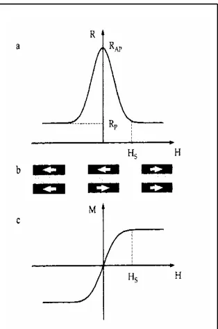
Figure 1.1 shows the schematic representation of GMR effect. The upper diagram (a), shows change in the resistance of the magnetic multilayer as a function of applied magnetic field. The middle diagram (b), is the magnetization configurations (indicated by the arrows) of the multilayer at various magnetic field. The diagram shows that the magnetizations are aligned antiparallel at zero field whereas the magnetizations are aligned parallel when the external fieldHis larger than the saturation field Hs. The lower diagram (c), shows the magnetization curve of the magnetic
4
5
1.3 Research Objectives
This dissertation was carried out to reach the following objectives:
i. To fabricate and design the GMR structures by electron beam evaporation method.
ii. To study the effect of fabrication parameters and post-annealing parameters towards the GMR values.
iii. To investigate the dependencies of composition, annealing temperature and thickness on the GMR value.
1.4 Research Scopes
6
ferromagnetic materials and conducting materials; annealing temperature ranged from 200°C to 350°C; conducting layer thickness vary from 1 to 15 nm, and the number of the repetition of the bilayer from 1 to 20 bilayer. Structural characterizations using methods of Atomic Force Microscopy, Field Emission Scanning Electron Microscopy and X-Ray Diffractometry are also carried out as supportive evidences of the result obtained.
Atomic Force Microscope (AFM) was used to probe the surface morphology of the magnetic and non-magnetic thin film layer. Field Emission Scanning Electron Microscope (FESEM) was used to see the surface structure of the magnetic and non-magnetic thin film layer. X-Ray Diffractometer (XRD) was used to provide information about the crystallographic structure of the magnetic and non-magnetic layer.
1.5 Research Problem Statement
7
Different from GMR heads, an AMR heads employs a special conductive material that changes its resistance in the presence of magnetic field. As the head passed over the surface of the disk, this material changes its resistance as the magnetic fields changes corresponding to the stored patterns on disk. A sensor is used to detect these changes in resistance, which allows the bits on platter to be read. While the older AMR heads typically exhibit about 2% of resistance change when passing from one magnetic polarity to another, for GMR heads the value is between 5% to 8%. This means GMR heads can detect much weaker and smaller signals, which is the key to increasing areal density.
Magnetic disk drive products have had their areal density increased by factor of 35 million since the introduction of the first disk drive, in 1957. Since 1991, the rate of increase has accelerated to 60% per year, and since 1997 it has accelerated further to an incredible 100% per year (Wolf et. al, 2006). The acceleration was the result of the introduction of AMR read heads in 1991 and GMR read heads in 1997. Today, nearly all disk drives in the industry incorporated the GMR read-head design, which is faster in speed and smaller in size. The achievements of switching from AMR read head technology to GMR read head technology would not be possible without a detailed understanding of the physics of GMR.
8
Study on magnetic and non-magnetic material composition can provide better understanding on magnetic and non-magnetic coupling in GMR phenomenon. Detailed information about band structure and lattice matching could be associated. From the study on post annealing treatment, the GMR response on a range of annealing temperatures could be observed. Study on the number of bilayer could enhance the understanding of spin dependent transport where supportive evident to resistor model could be obtained. The GMR response towards increasing non-magnetic layer thickness could be provided from the non-magnetic layer thickness study.
1.6 Thesis Outline