Express 4110/4120
ISDN Router/Bridge
USER MANUAL
61200176L3-1A May 1999
Part Number:
Trademarks:
DMS-100 is a trademark of Northern Telecom, Inc.
Ethernet is a trademark of Digital Equipment Corporation, Intel Corporation, and Xe-rox Corporation.
ExpertISDN (patent number 5,715,241) is a trademark of ADTRAN, Inc. Macintosh is a registered trademark of Apple Computer, Inc.
Novell, NetWare, and Internetwork Packet Exchange (IPX) are registered trademarks of Novell, Inc.
Windows is a registered trademark of Microsoft Corporation. 5ESS is a registered trademark of LUCENT.
The Express 4110/4120 incorporate Synchronous Data Compression based on either IBM or hi/fn proprietary intellectual property depending on the time of manufacture. The following trademarks and copyrights are applicable:
Stacker LZS Compression
Copyright © 1989 Carnegie Mellon University All rights reserved.
Redistribution and use in source and binary forms are permitted provided that the above copyright notice and this paragraph are duplicated in all such forms and that any documentation, advertising materials, and other materials related to such distri-bution and use acknowledge that the software was developed by Carnegie Mellon University. The name of the University may not be used to endorse or promote prod-ucts derived from this software without specific prior written permission. This soft-ware is provided “as is” and without any express or implied warranties, including, without limitation, the implied warranties of merchantability and fitness for a partic-ular purpose.
hi/fn
5993 Avenida Encinas
Carlsbad, CA
901 Explorer Boulevard
P.O. Box 140000
Huntsville, AL 35814-4000
Phone: (256) 963-8000
© 1999 ADTRAN, Inc.
FCC regulations require that the following information be provided in this manual:
1. This equipment complies with Part 68 of the FCC rules. On the bottom of the equipment housing is a label that shows the FCC registration number and Ringer Equivalence Number (REN) for this equipment. If requested, provide this information to the telephone company.
2. If this equipment causes harm to the telephone network, the telephone company may temporarily discontinue service. If possible, advance noti-fication is given; otherwise, notinoti-fication is given as soon as possible. The telephone company will advise the customer of the right to file a com-plaint with the FCC.
3. The telephone company may make changes in its facilities, equipment, op-erations, or procedures that could affect the proper operation of this equipment; advance notification and the opportunity to maintain uninter-rupted service is given.
4. If experiencing difficulty with this equipment, please contact ADTRAN for repair and warranty information. The telephone company may re-quire this equipment to be disconnected from the network until the prob-lem is corrected or it is certain the equipment is not malfunctioning. 5. This unit contains no user serviceable parts.
6. An FCC compliant telephone cord with a modular plug is provided with this equipment. In addition, an FCC compliant cable appropriate for the dial backup option ordered is provided with this equipment. This equip-ment is designed to be connected to the telephone network or premises wiring using an FCC compatible modular jack, which is Part 68 compliant. 7. The following information may be required when applying to the local
telephone company for leased line facilities.
To ADTRAN service personnel: For continued protection against risk of fire, replace F1 with the same type and rating of fuse only: .2A, 250 V.
Service Type Digital Facility Interface Code
Service Order Code
Network Jacks
FEDERAL COMMUNICATIONS COMMISSION RADIO FREQUENCY INTERFERENCE STATEMENT
This equipment has been tested and found to comply with the limits for a Class B dig-ital device, pursuant to Part 15 of the FCC Rules. These limits are designed to provide reasonable protection against harmful interference in a residential environment. This equipment generates, uses, and can radiate radio frequency energy and, if not installed and used in accordance with the instructions, may cause harmful interference to radio or TV reception, which can be determined by turning the equipment off and on. The user is encouraged to try to correct the interference by one or more of the following measures:
• Reorient or relocate the receiving antenna.
• Increase the separation between the equipment and receiver.
• Connect the equipment into an outlet on a circuit different from that to which the receiver is connected.
• Consult the dealer or an experienced radio/TV technician for help.
Changes or modifications to this unit not expressly approved by ADTRAN will void the user's authority to operate the equipment.
ADTRAN YEAR 2000 (Y2K) READINESS DISCLOSURE
ADTRAN has established a Year 2000 program to ensure that our products and opera-tions will correctly function in the new millennium. ADTRAN warrants that all prod-ucts meet Year 2000 specifications regardless of model or revision. Information about ADTRAN’s Year 2000 compliance program is available at the following:
Web Site www.adtran.com
Product Matrix www.adtran.com/Y2Kfax.html Faxback Document Line (256) 963-8200
Y2K plans and product certifications are listed in the matrix
Y2K Project Line (256) 963-2200
CANADIAN EMISSIONS REQUIREMENTS
This digital apparatus does not exceed the Class B limits for radio noise emissions from digital apparatus as set out in the interference-causing equipment standard entitled "Digital Apparatus," ICES-003 of the Department of Communications.
Cet appareil nuerique respecte les limites de bruits radioelectriques applicables aux appareils numeriques de Class B prescrites dans la norme sur le materiel brouilleur: "Appareils Numeriques," NMB-003 edictee par le ministre des Communications.
CANADIAN EQUIPMENT LIMITATIONS
Notice: The Canadian Industry and Science Canada label identifies certified equip-ment. This certification means that the equipment meets certain telecommunications network protective, operational, and safety requirements. The Department does not guarantee the equipment will operate to the user’s satisfaction.
Before installing this equipment, ensure that it is permissible to be connected to the fa-cilities of the local telecommunications company. The equipment must also be in-stalled using an acceptable method of connection. In some cases, the company’s inside wiring associated with a single-line individual service may be extended by means of a certified connector assembly (telephone extension cord). Compliance with the above conditions may not prevent degradation of service in some situations.
Repairs to certified equipment should be made by an authorized Canadian mainte-nance facility designated by the supplier. Any repairs or alterations made by the user to this equipment, or equipment malfunctions, may give the telecommunications com-pany cause to request the user to disconnect the equipment.
Users should ensure for their own protection that the electrical ground connections of the power utility, telephone lines, and internal metallic water pipe system, if present, are connected together. This precaution may be particularly important in rural areas.
Users should not attempt to make such connections themselves, but should contact the appropriate electric inspection authority, or an electrician, as appropriate.
IMPORTANT SAFETY INSTRUCTIONS
When using your telephone equipment, basic safety precautions should always be fol-lowed to reduce the risk of fire, electric shock and injury to persons. The precautions are listed below.
1. Do not use this product near water (for example, near a bath tub, wash bowl, kitchen sink or laundry tub, in a wet basement or near a swimming pool).
2. Avoid using a telephone (other than a cordless type) during an electrical storm. There may be a remote risk of electric shock from lightning. 3. Do not use the telephone to report a gas leak in the vicinity of the leak. 4. Use only the power cord, power supply, and/or batteries indicated in the
manual. Do not dispose of batteries in a fire. They may explode. Check local codes for any special disposal instructions.
AFFIDAVIT REQUIREMENTS FOR CONNECTION TO DIGITAL SERVICES
• An affidavit is required to be given to the telephone company whenever digital terminal equipment without encoded analog content and billing protection is used to transmit digital signals containing encoded analog content which are intended for eventual conversion into voiceband analog signals and transmitted on the network.
• The affidavit shall affirm that either no encoded analog content or billing information is being transmitted or that the output of the device meets Part 68 encoded analog content or billing protection specifications. • End user/customer will be responsible to file an affidavit with the local
ex-change carrier when connecting unprotected CPE to a 1.544 Mbps or sub-rate digital services.
AFFIDAVIT FOR CONNECTION OF CUSTOMER PREMISES EQUIPMENT TO 1.544 MBPS AND/OR SUBRATE DIGITAL SERVICES
For the work to be performed in the certified territory of _______________
(telco name)
State of ________________
County of ________________
I, _____________________________ (name), _____________________
(business address), ____________________ (telephone number) being
duly sworn, state:
I have responsibility for the operation and maintenance of the terminal equip-ment to be connected to 1.544 Mbps and/or ________ subrate digital services. The terminal equipment to be connected complies with Part 68 of the FCC rules except for the encoded analog content and billing protection specifica-tions. With respect to encoded analog content and billing protection:
( ) I attest that all operations associated with the establishment, maintenance, and adjustment of the digital CPE with respect to analog content and encoded billing protection information continuously complies with Part 68 of the FCC Rules and Regulations.
( ) The digital CPE does not transmit digital signals containing encoded ana-log content or billing information which is intended to be decoded within the telecommunications network.
( ) The encoded analog content and billing protection is factory set and is not under the control of the customer.
( ) A. A training course provided by the manufacturer/grantee of the equip-ment used to encode analog signals; or
( ) B. A training course provided by the customer or authorized representa-tive, using training materials and instructions provided by the manufacturer/ grantee of the equipment used to encode analog signals; or
( ) C. An independent training course (e.g., trade school or technical institu-tion) recognized by the manufacturer/grantee of the equipment used to en-code analog signals; or
( ) D. In lieu of the preceding training requirements, the operator(s)/main-tainer(s) is (are) under the control of a supervisor trained in accordance with _________ (circle one) above.
I agree to provide _________________ (telco's name) with proper documenta-tion to demonstrate compliance with the informadocumenta-tion as provided in the pre-ceding paragraph, if so requested.
_________________________________Signature
_________________________________Title
_________________________________ Date
Transcribed and sworn to before me
This ________ day of ________, 199___
_________________________________
Notary Public
My commission expires:
Table of Contents
Quick Startup Guide ... Quick Start-1
Setting up the ISDN Line ... Quick Start-1 Connecting to an Internet Service Provider ... Quick Start-2 Internet Access using Network Address Translation (NAT) ... Quick Start-2 Multiprotocol Routing Between Two LANS ... Quick Start-3 Remote/Home Office Accessing the Corporate LAN ... Quick Start-3
Chapter 1 Understanding ISDN and the Express 4110/4120 ... 1-1
Table of Contents
Front Panel ... 1-14 Express 4110 LAN Indicators ... 1-14 Express 4110 WAN Indicators... 1-15 Express 4110 Test Indicators... 1-15 Express 4120 LAN Indicators ... 1-15 Express 4120 WAN Indicators... 1-15 Express 4120 Test Indicators... 1-15 Rear Panel ... 1-16 ISDN Connection ... 1-16 Ordering ISDN ... 1-18 Interoperability ... 1-18 Connecting to the Internet ... 1-18 Configuration ... 1-19 Security ... 1-19
Chapter 2 Installation... 2-1
ISDN Network Connection ... 2-1 4110 Local Area Network Connection ... 2-1 4120 Local Area Network Connection ... 2-1 Telephone Connection ... 2-2 Basic Telephone Service ... 2-2 Supplementary Services ... 2-2 DTMF Keypad ... 2-2 Customer Premises Wiring ... 2-3
Chapter 3 Terminal Menu Operation and Structure... 3-1
Table of Contents
Table of Contents
Table of Contents
Table of Contents
Table of Contents
Table of Contents
Table of Contents
PPP Log/View ... 3-75 PPP Log/Clear... 3-75 Logs/Call Log ... 3-75 Call Log/Active ... 3-76 Call Log/Wrap ... 3-76 Call Log/Level... 3-76 Call Log/View ... 3-76 Call Log/Clear ... 3-76 Logs/Network Log ... 3-76 Network Log/Active ... 3-76 Network Log/Wrap... 3-76 Network Log/Level ... 3-77 Network Log/View ... 3-77 Network Log/Clear ... 3-77 Utilities Menu ... 3-78 Utilities/Ping ... 3-78 Utilities/Telnet Client ... 3-79 Utilities/Upgrade Menu ... 3-79 Upgrade/Transfer Method ... 3-79 Upgrade/Filename... 3-79 Upgrade/Start Transfer... 3-80 Utilities/Exit ... 3-80
Chapter 4 Troubleshooting ... 4-1
If Self-Test Fails ... 4-1 If the Express 4110/4120 does not read Ready ... 4-1 If You are Unable to Connect Calls ... 4-6
Chapter 5 Specifications ... 5-1
Table of Contents
Appendix A Loop Status Messages ... A-1
Appendix B Log Messages ...B-1
Appendix C SNMP ... C-1
Appendix D Connector Pinouts ... D-1
Appendix E Terminal Mode Commands ... E-1
Glossary ... Glossary-1
Acronyms... Acronyms-1
List of Figures
Figure 1-1. Express 4110 ... 1-2 Figure 1-2. Express 4120 ... 1-2 Figure 1-3. Single User to Corporate LAN (4110) ... 1-3 Figure 1-4. Single User to Corporate LAN (4120) ... 1-3 Figure 1-5. Single User to Internet Service Provider (4110) ... 1-4 Figure 1-6. Single User to Internet Service Provider (4120) ... 1-5 Figure 1-7. Multiple User to Internet Service Provider (4110) ... 1-6 Figure 1-8. Multiple User to Internet Service Provider (4120) ... 1-7 Figure 1-9. SOHO to Corporate LAN (4110) ... 1-8 Figure 1-10. SOHO to Corporate LAN (4120) ... 1-9 Figure 1-11. Express 4110 LEDs ... 1-14 Figure 1-12. Express 4120 LEDs ... 1-15 Figure 1-13. Express 4110 Rear Panel ... 1-17 Figure 1-14. Express 4120 Rear Panel ... 1-17 Figure 2-1. Wiring Scheme 1: Use existing analog telephone equipment,
but replace single analog telephone service with ISDN service ... 2-4 Figure 2-2. Wiring Scheme 2: Retain single analog telephone service
List of Figures
List of Tables
Quick Startup Guide
SETTING UP THE ISDN LINE
Before configuring the Express 4110/4120, ensure that the telephone ser-vice has provided the switch type, serser-vice profile identification (SPID), and local directory number (LDN).
Example:
1. Connect a VT 100 async terminal, or personal computer with a termi-nal emulator running 9600 N-8-1, to the MAINTENANCE port. 2. Hold down the Control key and press R; then press Enter to display
the top menu.
3. Using the arrow keys and Enter key to navigate the menu, go to the
Configuration/WAN/ISDN/Dial Line menu. Enter the SPIDs, LDNs, and switch type.
4. Use the left arrow key or the Escape key to go back up the menu tree. When asked to save ISDN parameters, type y.
5. Connect the ISDN line to the RJ-49C jack labeled ISDN on the rear panel.
6. When the PWR LED remains solid, the Express 4110/4120 is ready for calling.
Switch Type National ISDN-1 SPID1 20555512120100 SPID2 20555512130100 LDN1 5551212
Quick Startup Guide
7. If using a POTS phone with the Express 4110/4120, connect the POTS telephone to the POTS port.
If the SPID(s) does not work or is unknown, try activating the ExpertISDN™ feature. First enter the area code and local directory number(s); then press the Enter key over the ExpertISDN activator.
CONNECTING TO AN INTERNET SERVICE PROVIDER
Internet Access using Network Address Translation (NAT)
1. Connect the Express 4110/4120 to the 10BaseT LAN.
2. Go to the Configuration/Connection List menu, and then press the right arrow key to place the cursor on the Num column.
3. Type I to insert a new Connection List entry.
4. Using the arrow keys, move the cursor over the Num column for the inserted entry. Press Enter to place the subentries into the right pane. 5. Set the Description to an identifiable name (i.e., ISP).
6. Go into the Authentication field and select PAP or CHAP for the Tx
Method.
7. Enter your user name and password (provided by your ISP) into the
Tx Username and Tx Password fields.
8. Move the cursor to the left pane and highlight the IP parameters. 9. Set the NAT item to ON. This is a very important step. The Express
4110/4120 will need to translate the “fake” IP address(es) on the PC(s) to the “real” address provided dynamically by the ISP. See “IP/NAT” on page 3-18 for more details.
10. If you want the 4110 to automatically connect to your ISP whenever you try to access the Internet, go into the Route field and enter the IP address and mask of the ISP router. If the address of the ISP router is not known, enter a bogus address such as 172.16.1.1 with mask 255.255.0.0 and the 4110 will dynamically resolve the correct address of the ISP router. Otherwise, all other IP parameters should be left at their default settings.
11. Navigate to the Dial Out parameters. Enter the telephone number provided by the ISP into Number 1. If the ISP is providing you a mul-tilink PPP (2 B channel), enter Number 2 if it is provided. Set Initial
Quick Startup Guide
12. If the ISP does not support the Bandwidth Allocation Control Protocol (BACP), navigate to the PPP parameters. Go into the Multilink field and disable BACP.
13. If you want the 4110 to automatically disconnect from the ISP after communication with the Internet has ceased for some period, navi-gate to the Bandwidth parameters. Go into the On Demand field and set Mode to On; then set Idle Timeout to the period desired. 60 sec-onds is a commonly used value. In this mode, the 4110 will also con-nect the second B channel when the bandwidth is not needed. 14. Arrow left until the message Save Connection List Changes appears.
Type y to save.
15. Go to the Configuration/IP menu and enter an IP address and net mask into the IP Address and Subnet Mask fields. The factory default setting will work just as well (10.0.0.1, 255.255.255.0). 16. Set the Default Gateway field to the IP address of the ISP router. If
the address of the ISP router is not known, enter a bogus address such as 172.16.1.1 as in step 10. This setting, and the settings from step 10, let the 4110 know to automatically call the ISP whenever you try to access the Internet.
17. Go into the Configuration/IP/NAT submenu and set DHCP Mode to
On.
18. Arrow left to save the configuration.
19. On your computer or on the 4110 under Configuration/IP/DNS, con-figure the DNS settings provided by the ISP. Refer to your PC’s user manual or help screen if setting these numbers on your PC.
20. If your computer is configured to dynamically get its IP address using DHCP, the 4110 is now ready to assign the address. The PC must generate a DHCP request to obtain the IP parameters needed to get on the Internet. Refer to your PC’s user manual or help screen.
If you prefer to manually connect to the ISP as opposed to letting the 4110 dynamically connect, complete steps 21-23. Otherwise, use your com-puter to try and access the Internet, and go to step 24.
21. Go into the Dial menu.
22. Set the cursor over the Dial parameter for the Connection List profile you just set up.
Quick Startup Guide
24. If the call is successful, the Status column will read active. If not, make sure the number(s) are correct or reference “Troubleshooting” on page 4-1 before continuing.
25. Once the call is up, the PC must generate a DHCP request to obtain the IP parameters needed to get on the Internet. Refer to your PC’s user manual or help screen.
MULTIPROTOCOL ROUTING BETWEEN TWO LANS
Remote/Home Office Accessing the Corporate LAN
The following steps can be used to set up the Express 4110/4120 on a remote LAN to access a corporate or central LAN using demand dial and dynamic bandwidth management.
1. Connect the Express 4110/4120 to the 10BaseT LAN.
2. Set the IP address and Subnet Mask assigned by the network admin-istrator in the Configuration/IP menu.
3. For the Default Gateway, enter the IP address of the access server at the remote site. This creates a default route in the IP routing table that will be used with the dial-on-demand feature in the Express 4110/ 4120.
4. Use the arrow keys to get to the Configuration/IPX menu. Set the
Network value to the IPX network supplied by the network adminis-trator. Set the Seed Status to Seed. Arrow left and save the changes with a y when prompted.
5. Move to the Configuration/Connection List. Use the arrow keys to move the cursor over the Num column. Type I to insert a new entry. 6. Move the cursor over the Description field and press Enter. A pop-up
window appears in which to enter a name for this Connection List profile.
7. Move the cursor over the Authentication menu and press Return. This will place the authentication parameters into the right pane. 8. Enter the username and password under Tx Username and Tx
Pass-word. These items should be provided by the administrator at the site being dialed.
9. Use the down arrow to display the IP menu parameters in the right pane.
Quick Startup Guide
11. Enter the IP address and Netmask parameters of the access server at the remote site. This creates a static route to the access server’s net-work which is entered into the Express 4110/4120’s IP route table. 12. Move the cursor over the RIP menu. Check with the network
admin-istrator for the type of routing protocol used. The Express 4110/4120 supports RIP versions 1 and 2. The protocol is set in the Protocol parameter.
13. Select Yes for the Triggered parameter. This prevents periodic RIP updates that keep the ISDN link from going “idle.”
14. Select Yes for the Retain parameter. This allows the routes learned from the access server to be saved in the IP routing table. Access to any of those networks from the workstation will cause this profile to be dialed.
15. Use the left arrow to get back to the previous menu. Use the down arrow to view the IPX menu parameters in the right pane.
16. This is similar to steps 13 and 14. Select Yes for Triggered and Yes for
Retain. This allows the ISDN link to go to an idle state and permits the Express 4110/4120 to “spoof” the server information obtained from the access server. A similar configuration must be selected on the access server.
17. Use the arrows to get the Dial Out menu parameters for this profile. 18. Enter the phone number of the access server in Number 1. If
config-ured by the administrator to use two B-channels using Multilink PPP, set the Initial Channels field to 2. Some PPP protocols, if they exist in the access server, will allow the second channel to come into play only if the bandwidth is needed. If this is the case, the Express 4110/ 4120 will automatically negotiate this with the access server.
19. Now move to the Bandwidth menu for this profile. Once there, use the right arrow to move to the On Demand submenu.
20. Set the Mode parameter to On. This enables the dynamic bandwidth features of the Express 4110/4120.
21. Select the Idle Timeout parameter and enter the number of seconds the Express 4110/4120 should wait before hanging up the connection when no traffic is present. A value of 120 seconds is typical. A value of 0 means never idle the link.
Quick Startup Guide
23. Set up the computer workstation’s IP and IPX parameters as
instructed by the network administrator. The Express 4110/4120’s IP address should be the computer’s default gateway.
When the computer which is attached to the local LAN attempts to access a host on the access server, the Express 4110/4120 will dial the number provided in the Connection List profile. The Express 4110/4120 will pro-vide one of two B-channels based on traffic demand and POTS port usage. If no packet traffic is transmitted or received for the specified number of seconds, the Express 4110/4120 will disconnect the link until a computer on the local LAN again attempts to access a host on the access server.
If Novell’s IPX protocol is being used, the link must be dialed first in the
Chapter 1
Understanding ISDN and the
Express 4110/4120
ISDN OVERVIEW
The Integrated Services Digital Network (ISDN) is a public or private switched digital network. ISDN is an international standard for digital communications, allowing a full range of enhanced services supporting voice, data, and image applications through standard interfaces over a single telephone wire. ISDN provides a means of integrating these ser-vices and modernizing communication networks for information move-ment and managemove-ment efficiency.
THE EXPRESS 4110/4120
The Express 4110/4120 is a standalone device that links two Local Area Networks (LANs) using a high-speed ISDN public network or leased two-wire line. It also contains two plain old telephone service (POTS) connectors used for voice/modem applications
Chapter 1. Understanding ISDN and the Express 4110/4120
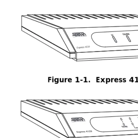
Figure 1-1. Express 4110
Figure 1-2. Express 4120
Applications
Single User to Corporate LAN
• Telecommuter/Home Office Access to the corporate LAN • Single device access
• User Datagram Protocol (UDP) broadcasts are “relayed” to corporate LAN.
• Client device can obtain the Internet Protocol (IP) address dynami-cally using Dynamic Host Configuration Protocol (DHCP).
• Compatible with popular central site LAN access devices
Chapter 1. Understanding ISDN and the Express 4110/4120
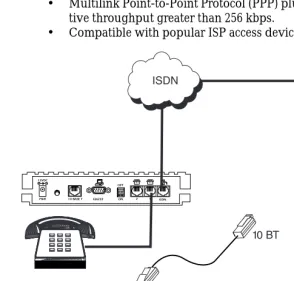
Figure 1-3. Single User to Corporate LAN (4110)
Chapter 1. Understanding ISDN and the Express 4110/4120
Single User IP to Internet Service Provider (ISP) using Network Address Translation (NAT)
• Provides high speed home access to the Internet
• NAT provides translation from user assigned IP addresses to ISP assigned IP addresses.
• The PC’s IP address can be dynamically assigned by the Express 4110/4120.
• Overcomes the serial port speed limitations of current terminal adapter solutions
• Multilink Point-to-Point Protocol (PPP) plus compression yields effec-tive throughput greater than 256 kbps.
• Compatible with popular ISP access devices
Chapter 1. Understanding ISDN and the Express 4110/4120
Chapter 1. Understanding ISDN and the Express 4110/4120
Multiple Users to Internet Service Provider (ISP) using NAT
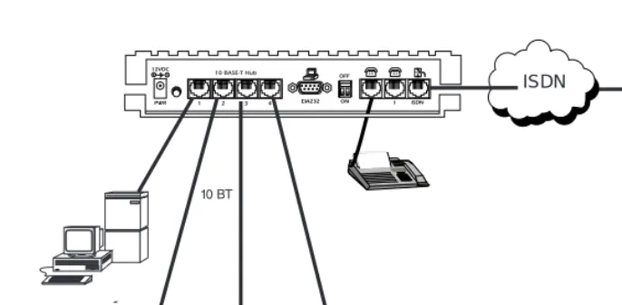
• Provides high speed home access to the Internet • Multiple and simultaneous access
• The PC’s IP address can by dynamically assigned by the Express 4110/4120.
• On-demand Internet access
• Multilink PPP plus compression yields effective throughput greater than 256 kbps.
• Compatible with popular ISP access devices
Chapter 1. Understanding ISDN and the Express 4110/4120
Figure 1-8. Multiple User to Internet Service Provider (4120)
Chapter 1. Understanding ISDN and the Express 4110/4120
Small Office - Home Office (SOHO) to Corporate LAN
• Connects the small office or home office to the corporate LAN • Routes IP and Internet Packet Exchange (IPX) traffic from multiple
devices to the corporate LAN
• Bridges all non-routed traffic (e.g., AppleTalk) • Provides dedicated or on-demand services • Low-cost alternative to buying a high-end router
• Compatible with popular central site LAN access devices
Chapter 1. Understanding ISDN and the Express 4110/4120
Figure 1-10. SOHO to Corporate LAN (4120)
The Express 4110/4120 provides the following basic functions:
1. LAN Bridge: Bridging provides a point-to-point connection between two LANs. The bridge learning function scans the source and desti-nation media access control (MAC) addresses of all packets on its local LAN and determines which packets should be transmitted over the ISDN link. Applications include connectivity between single user or small offices to corporate LANs. The Express 4110/4120 uses the Spanning Tree Algorithm (IEEE 802.1d-ISO/IEC10038), which provides a loop-free topology and redundancy.
2. IP Router: The Express 4110/4120 can function as an IP router using the Routing Information Protocol (RIP) for advertising and learning routes among other routers. Static routes may also be entered into the routing table.
Chapter 1. Understanding ISDN and the Express 4110/4120
4. Network Address Translation (NAT): Single networks can connect to the Internet with this function. The Express 4110/4120 translates out-going IP packets over the ISDN to the IP router at the Internet Service Provider. Popular Internet applications are supported.
5. POTS: The POTS interfaces can be used for interfacing to dual tone multi-frequency (DTMF) analog devices such as telephones, modems, fax machines, etc.
Demand Routing and Bridging with the Express 4110/4120
The Express 4110/4120 is a dial-up ISDN IP Router and Transparent Learning Bridge that provides Dial-On-Demand and Dynamic Bandwidth Management. Its features can be easily configured and used once several basic concepts are understood.
Factory Default
The Express 4110/4120 comes from the factory configured for MAC Bridging, IP routing, and IPX routing with no filters or connection infor-mation defined. An IP address of 10.0.0.1 with a network mask of
Chapter 1. Understanding ISDN and the Express 4110/4120
Bridging
In Bridge Mode, the Express 4110/4120 can communicate with two remote networks at a time. The destination is dialed by setting up a Con-nection List profile and choosing Dial on the Dial menu. See “Configura-tion/Connection List” on page 3-36 for instructions on setting up a Connection List profile.
During a two B-channel PPP Multilink call, the Express 4110/4120 auto-matically drops one B-channel and provides it to the POTS port when a telephone call is placed or answered. When a POTS telephone call termi-nates, the Express 4110/4120 redials the second B-channel and supplies the bandwidth back to the LAN connection. Since other bandwidth man-agement features are disabled in the factory default configuration, the dialed links remain active until the Hang-up command is entered from the Dial menu, terminating the session with the selected remote network.
The Connection List described in the next section may be used to auto-mate dialing and to store additional information specific to the remote site being dialed (phone numbers, number of B-channels to dial, authen-tication information, Caller ID, etc.). In addition, to reduce line charges, Demand Dialing may be enabled to allow idle links to disconnect when not being used.
Simple Demand Bridging may be configured by enabling the Idle Time-Out parameter under the Configuration/ Connection List
Chapter 1. Understanding ISDN and the Express 4110/4120
IP Routing
The Express 4110/4120 operates as a dial-up IP router when the
Configu-ration/IP/IP Router/Mode option is configured to On. The Express 4110/ 4120 uses an IP unnumbered WAN interface; the IP address and mask assigned to the unit’s LAN interface apply to all routing and IP operations for the unit. If a default gateway is specified on the network of the Ether-net interface, the unit attempts to reach the gateway through that inter-face. If the gateway is specified on an unknown network, the unknown network is assigned to the router table and remains unused until that gateway becomes the peer on a WAN connection. If no default gateway is specified, the first connected peer on the WAN interface becomes the default gateway (recommended for remote applications when there are no other routers on the remote LAN).
For each profile in the Connection List that includes an IP address and has the Configuration/Connection List/IP/Route/Static Route option set to
Yes, the Network Address of the specified IP address is added to the router table with the Host Address as the gateway. If the Configuration/
Connection List/IP/Route/Private option is set to No, the route is adver-tised at the specified metric through the unit’s interfaces as if a connection is active to that network. These routes are referred to as spoofed routes.
Attempts by any computer connected to the LAN interface to access a host on a spoofed network causes a connection to be attempted using the information from that Connection List profile. Once connected, routes advertised by the peer router are learned and advertised to the local LAN. If Bandwidth-On-Demand is enabled and an Idle Time-out value is speci-fied, expiration of the Idle Timer causes the link to be disconnected; the routes learned from the peer router are retained if the Configuration/
Connection List/IP/RIP/Retain option is set to Yes and advertised as if the connection is still active. These routes are referred to as retained routes. Attempts by any connected computer to access a host on any of the retained routes causes the link to be redialed. If Hang Up is activated from the Dial menu when the link is down, the retained routes are removed.
Chapter 1. Understanding ISDN and the Express 4110/4120
IPX Routing
Like IP routing, the Express 4110/4120 can connect to two different sites and exchange IPX packets. Network routes and services are learned and advertised using Novell’s RIP and SAP. Routes and services learned from a separate site can be retained in the Express 4110/4120 when the connec-tion goes idle. While retained, the Express 4110/4120 can spoof RIP/SAP and watch-dog and filter serialization packets that would normally be required between the Novell server and client.
Connection List - Simplifying and Enhancing the Dial Function
The Connection List, which is accessed from the Configuration menu, provides a location to define information regarding 15 individual desti-nations that may be dialed. A Connection List entry is required for each destination since authentication information (method, username, pass-word), number of B-channels, telephone numbers, Caller ID, IP, or IPX address (for routed connections), and other information can be stored for each destination defined. Defined destinations may be dialed by select-ing the Dial activator in the Dial menu or by demand for the desired Connection List profile.
Concurrent Routing and Bridging
The Express 4110/4120 can route IP and IPX as well as bridge non-IP/IPX packets simultaneously. The Connection List profile will by default nego-tiate PPP network protocols to support the transmission and reception of IP, IPX, and Bridge packets. If the PPP peer does not accept a protocol, the Express 4110/4120 will fall back to any combination of routing and bridg-ing.
Routing over PPP Bridging
Chapter 1. Understanding ISDN and the Express 4110/4120
Network Address Translation Mode
NAT is a special mode of operation in which the Express 4110/4120 obtains a dynamically assigned IP address from the peer router (typically an Internet Service Provider). This allows a network of computers to ben-efit from Ethernet to ISDN speeds while still appearing to the Internet Ser-vice Provider (or central site router) as a single IP address, which is typical of PC based serial dial-up solutions.
A call is initiated to the ISP using the Dial menu or demand for a Connec-tion List profile that has the IP parameter NAT set to Yes. The network computer’s IP stack may use DHCP to request an IP address, default gate-way address, and domain name server addresses from the Express 4110/ 4120.
Front Panel
Figure 1-11 on page 1-14 shows the front panel of the Express 4110. Figure 1-12 on page 1-15 shows the front panel of the Express 4120. The indica-tors are divided into LAN functions, WAN functions, and Test functions.
Figure 1-11. Express 4110 LEDs
Express 4110 LAN Indicators
TX/RX Flashes green when transmitting data onto the 10BaseT connector.
Flashes yellow when receiving data from the 10BaseT connector.
LI Link integrity. Illuminates when there is a good connection between the Express 4110 and a NIC card.
Chapter 1. Understanding ISDN and the Express 4110/4120
Express 4110 WAN Indicators
PWR Flashes when the link is inactive; solid when the link is active. Phone 1/2 Flashes green when the link is being negotiated; off when the link is
active. After the link is active, 1 flashes green when a call on POTS line 1 is in progress; solid green when a call is connected.
Express 4110 Test Indicators
Phone 1/2 A slow amber flash indicates test in progress; a fast amber flash indi-cates test has failed.
Figure 1-12. Express 4120 LEDs
Express 4120 LAN Indicators
1, 2, 3, 4 Link integrity. Illuminates when there is a good connection between the Express 4120 and a NIC card.
TX/RX Flashes green when transmitting data onto the 10BaseT connector.
Flashes yellow when receiving data from the 10BaseT connector.
Express 4120 WAN Indicators
PWR Flashes when the link is inactive; solid when the link is active. Phone 1/2 Flashes green when the link is being negotiated; off when the link is
active. After the link is active, 1 flashes green when a call on POTS line 1 is in progress; solid green when a call is connected.
Express 4120 Test Indicators
Chapter 1. Understanding ISDN and the Express 4110/4120
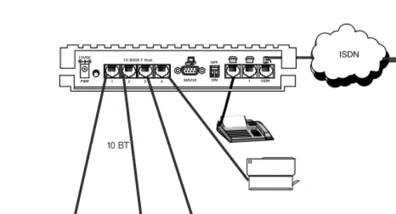
Rear Panel
The Express 4110/4120 has one RJ-49C jack, labeled ISDN, on the rear panel for network connection (see Figure 13 on page 17 and Figure 1-14 on page 1-17). The OFF/ON switch block is for factory default and firmware downloading. With switch 1 in the up or OFF position, the Express 4110/4120 will go immediately into a download mode when power is enabled. Switch 1 must be in the down or ON postition in order to boot up normally. Switch 2 in the up or OFF position will force the entire configuration to be factory defaulted.
ISDN Connection
From the network, ISDN is delivered by a single 2-wire 2B1Q U-interface which is connected directly to the Express 4110/4120. ISDN network ter-mination is designed into the Express 4110/4120, eliminating the need and expense of a separate NT1. For network testing, the Express 4110/ 4120 responds to NT1 test commands from the telephone company cen-tral office (CO).
The Express 4110/4120 has one RJ-49C jack, labeled ISDN, on the rear panel for network connection (see Figure 13 on page 17 and Figure 1-14 on page 1-17). ISDN basic rate service divides a standard telephone line into three digital channels capable of simultaneous voice and data transmission. The three channels are comprised of two bearer (B) chan-nels at 64 kbps and one data (D) channel at 16 kbps, known as 2B+D.
Chapter 1. Understanding ISDN and the Express 4110/4120
Figure 1-13. Express 4110 Rear Panel
Chapter 1. Understanding ISDN and the Express 4110/4120
Ordering ISDN
When ordering ISDN from the telephone company, request EZ-ISDN 1 (Capability Package U) to ensure it is set up properly. EZ-ISDN 1 is rec-ommended by the industry for most home office/small business applica-tions. If this is not available from your service provider or you would like more information regarding ordering ISDN, see the ADTRAN document
Ordering ISDN Service User Guide part number 60000.015-8 or contact your
telephone company for alternative line configurations. The Ordering
ISDN Service User Guide is available on the ADTRAN home page at http:// www.adtran.com or by calling ADTRAN.
Interoperability
The Express 4110/4120 is standards based and uses PPP developed by Internet Engineering Task Force (IETF). PPP provides a standard method of transporting multiprotocol datagrams over point-to-point links. PPP is widely accepted by many ISDN bridge/router manufacturers. The Express 4110/4120 will negotiate Multilink PPP when connecting both B-channels. The Bandwidth Allocation Protocol (BAP) may also negotiate, which enhances the management of adding and removing a B-channel. Data compression is also supported using LZS® technology from hi/fn™.
Connecting to the Internet
Internet Service Providers (ISPs) assign an IP address to use when con-nected to their service using PPP negotiation. This assignment is based on the assumption that the user has an ISDN terminal adapter running PPP async-to-sync conversion or another rate adaption where the PPP negotiation is terminated inside the PC’s IP stack. However, if an ISDN-Ethernet gateway device is used, the ISP must preassign the customer a subnet which uses multiple IP addresses. This may result in a much higher cost to the user.
Configura-Chapter 1. Understanding ISDN and the Express 4110/4120
tion/IP/NAT menu that allows incoming HTTP, FTP, and mail server requests from the Internet to be translated and forwarded to this address on the user network.
Configuration
The Express 4110/4120 is configured using a menu-based interface. This interface can be accessed via the maintenance port using any asynchro-nous VT 100 terminal or personal computer running a terminal emula-tion program, or via the LAN using a Telnet client program. To use the Telnet interface, the Express 4110/4120 must first have an IP address pro-grammed into it via the maintenance port. The factory default is 10.0.0.1.
Security
Security on network devices is a major concern for almost anyone with a network. The Express 4110/4120 provides many tools for securing the local network from hostile users. Incoming calls can be authenticated using passwords and Caller ID. A RADIUS client can also be used.
The Telnet configuration can also be protected using the same authentica-tion methods. Each menu item in the Express 4110/4120 has a security level associated with it. A Telnet session is assigned a privilege level which determines which menu items are accessible to the Telnet client. See “Security Levels” on page 3-7 (in Chapter 3) for more information on menu security levels.
Chapter 2
Installation
After unpacking the unit, immediately inspect it for possible shipping damage. If damage is discovered, file a claim immediately with the ship-ping carrier; then contact the ADTRAN CAPS department (see back page).
ISDN NETWORK CONNECTION
The Express 4110/4120 supports either dial or leased operation. A single RJ-49C modular jack labeled ISDN on the rear panel provides connection to either network service. Dial operation allows the user to dial out or receive calls over the public network. The leased operation mode sup-ports dedicated 2B1Q data service at rates up to 128 kbps by using a nailed up circuit, or a permanent connection between endpoints.
See “Connector Pinouts” on page D-1 for ISDN network connector pin assignments.
4110 LOCAL AREA NETWORK CONNECTION
The Express 4110 has a single 10BaseT connection port that provides half duplex 10 Mbps operation over a 4-wire twisted pair. Other types of Ethernet interfaces (i.e., AUI, 10Base2, etc.) can be accommodated by obtaining an appropriate converter.
4120 LOCAL AREA NETWORK CONNECTION
Chapter 2. Installation
To connect to an NIC you will need a straight-through cable. To connect to another hub you will need an Ethernet crossover cable, unless the hub you are connecting to has a crossover switch. See Appendix D for 10BaseT connector pin assignments.
TELEPHONE CONNECTION
Basic Telephone Service
The Express 4110/4120 supports an analog DTMF telephone (type AT&T 2500) with the POTS interface. Two telephones or other analog devices (like a fax machine or modem) plug into either RJ-11 jack (labeled with drawings of telephones) on the rear of the unit. Using a multipoint line allows the POTS and data port to have unique phone numbers.
Supplementary Services
Supplementary services such as call holding, three- or six-way conferenc-ing, call transfer, and call waiting are fully supported by the Express 4110/4120 on a touch-tone telephone. Table 2-1 explains how the flash-hook is used for handling multi-call situations.
DTMF Keypad
The following functions are performed on a touch-tone phone:
Disable call waiting: Press **0
Enable call waiting: Press **1
Redial last number: Press **5
Enable ExpertISDN: Press **6
Enter Area Code: Press **7XXX (where XXX is a 3-digit area code. This must be entered first, before enabling ExpertISDN.)
Enter Phone Number 1: Press **8XXXXXXX (where XXXXXXX is the 7- digit phone number. This must be entered before enabling Exper-tISDN.)
Chapter 2. Installation
Table 2-1. Using the Flash-Hook
Calling a second party with an active call:
Flash-hook to place active call on hold and dial new number. Hanging up will terminate the call.
Answering an incoming call with an active call at call waiting:
Flash-hook to place active call on hold and answer incoming call. Hang-ing up will terminate both calls.
Conferencing Calls:
With an outgoing call on hold, and a second outgoing call active, flash-hook to conference calls. Hanging up will transfer second call.
With an incoming call on hold, and outgoing call active, flash-hook to conference calls. Hanging up will transfer calls.
With two incoming calls (one on hold and one active) flash-hook to con-ference calls. Hanging up transfers calls.
Answering calls on hold, and holding incoming active calls:
Flash-hook places the incoming call on hold and reconnects to outgoing call. Hanging up will terminate both calls.
When connecting to a National ISDN 1 switch, call conferencing and call transferring are as-signed a unique feature identifier number. This number may not be the same in all areas. The Configuration/WAN/POTS menu contains the feature identifier numbers for conference and transfer. If these features do not work, contact your ISDN provider. They can determine the numbers for these features that can then be programmed into the Express 4110/4120.
Customer Premises Wiring
Chapter 2. Installation
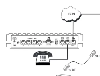
Figure 2-1. Wiring Scheme 1: Use existing analog telephone equipment, but replace single analog telephone service with ISDN service
Chapter 2. Installation
Figure 2-2. Wiring Scheme 2: Retain single analog telephone service and add ISDN service
Chapter 3
Terminal Menu Operation and
Structure
TERMINAL MENU STRUCTURE
The Express 4110/4120 uses a multilevel menu structure containing both menu items and data fields. All menu operations and data display in the terminal menu window. The Express 4110/4120 is shipped in the Factory Default configuration. Connect any VT 100 or VT 220 type terminal emu-lator to the maintenance port. The default rate is 9600 baud 8-N-1. The terminal emulator can flow the Express 4110/4120 off using software flow control. Hardware flow control is not used.
The opening menu (the Main menu, or top-level menu) is the access point to all other operations. Each Main menu item has several functions and submenus to identify and access specific parameters. “Top Level Termi-nal Menu” on page 3-2 shows the top-level termiTermi-nal menu. The Main menu options are described below.
Chapter 3. Terminal Menu Operation and Structure
Figure 3-1. Top Level Terminal Menu
Menu Path - Gives current position in terminal menu structure.
Right Pane - Lists available submenus. More sub-menus available through this pane are indicated by the [+] and [DATA] symbols.
Left Pane - Lists available menus.
Mode - Describes current operating mode.
Loop Status - Dis-plays current status of ISDN line.
B-channel status - Displays current status of each B channel.
Chapter 3. Terminal Menu Operation and Structure
Configuration
The Configuration menu provides options to set up the operational con-figuration for the Express 4110/4120. See the section “Concon-figuration Menu” on page 3-8 for detailed information.
Dial
The Dial menu is used to connect to different sites based on the Connec-tion List. See the secConnec-tion “Dial Menu” on page 3-62 for more details.
Status
The Status menu provides options to review and monitor the status of the Express 4110/4120 system. See the section “Status Menu” on page 3-64 for detailed information on the available options.
Test
The Test menu can be used for performing diagnostic testing of the Express 4110/4120. See the section “Test Menu” on page 3-73 for detailed information on the tests available.
Logs
The Logs menu can be used for viewing the operational logs for the Express 4110/4120. See the section “Logs Menu” on page 3-74 for detailed information on the available options.
Utilities
Chapter 3. Terminal Menu Operation and Structure
NAVIGATING THE TERMINAL MENUS
The following sections provide information on how to navigate through the terminal menus.
General Layout
When you first start a terminal mode session, the window shown in “Top Level Terminal Menu” on page 3-2 displays. The screen is divided into left and right panes. The left pane shows the current list of submenus, while the right pane shows the contents of a selected submenu.
Menu Path
The top line of the display shows this session’s current position (path) in the menu tree. Figure 3-1 shows the top menu level with the cursor on the Configuration submenu, so the path display shows Express
4110/Config-uration.
Moving Around
Press Tab or the right arrow key to move the cursor from the left pane to the right pane. Press Tab or the left arrow key to move the cursor from the right pane back to the left pane. Use the up and down arrows to move around within each pane. Press Enter to activate a menu. Press the left arrow key or the Escape key to go back up the menu. The following options display throughout the menus.
Submenus [+] or [DATA]
Menus that display [+] or [DATA] indicate that more items are available when selected.
Activation Field <+>
Menus that display <+> indicate that an action is to be taken, such as acti-vating a test.
Editable Data Field
A highlighted menu item indicates that you can enter data in that field.
Read-Only Field
Chapter 3. Terminal Menu Operation and Structure
Navigation with the Keyboard
You can use different keystrokes to navigate through the terminal menu. Press Control-Z to activate a pop-up screen with the available keystrokes. The following section provides a list of the available keystrokes and the results:
General Navigation
H Returns to the home screen.
J Jumps between two menu items. Press J while on a menu item of interest, and you will jump back to the main screen. Go to another menu item of interest, Press J, and you will jump back to the screen that was displayed the first time you pressed J. Press J anytime you want to jump between these items. Arrow Keys Selects items and moves between the left and right panes. The
left arrow key allows you to go back up the menu. Enter Activates an item or moves into submenu.
Escape Cancels an edit. Allows you to go back up the menu. Also will dismiss the pop-up help screens.
Tab Moves between the left and right panes. A Moves to the top of a screen.
Z Moves to the bottom of a screen. Backspace Ascends one menu level.
Session Management
Control-L Logs out of the session.
Control-S Invalidates the password entry and returns to the login screen. The Password prompt will display.
Chapter 3. Terminal Menu Operation and Structure
Configuration
F Restores factory default settings. This setting restores the factory defaults based on the location of the cursor. Entire submenus can be factory defaulted.
C Copies selected items to the clipboard. The amount of informa-tion you can copy depends on the cursor locainforma-tion when you press C. For example, if the cursor is over an editable field, only that item is copied. If the cursor is over the index number of a list, then all of the items in the row of the list are copied. For example, if the cursor is over the Num field in the Connection List screen, all of the information associated with the Connec-tion List entry is copied.
P Pastes the item stored in the clipboard, if the information in compatible. You must confirm all pastes except those to a single editable field.
> For certain types of fields, when you paste information into the field, the value increments by 1.
< For certain types of fields, when you paste information into the field, the value decrements by 1.
I Inserts a new item in a list. For example, add a new item to the Connection List by pressing I while the cursor is over the index number.
Chapter 3. Terminal Menu Operation and Structure
Security Levels
Each menu item on the configuration screens has an associated security level. The security level ranges from 0 (highest security level) to 5 (lowest security level). This level determines whether a Telnet session can access that menu item. The Telnet session is assigned a security level set by the user. Passwords can only be accessed as security level 0. The maintenance port is always at security level 0.
The security levels are assigned as follows:
Level
0 Access all parameters including passwords 1 Access all parameters except passwords 2 Access all parameters except passwords and
authentication methods
3 Access all parameters except passwords, authentication methods, and ISDN parameters 4 Access only test and status menus
Chapter 3. Terminal Menu Operation and Structure
CONFIGURATION MENU
Configuration/System Info
The System Info menu provides basic information about the unit and dis-plays data fields for editing information. Figure 3-2 disdis-plays the sub-menus available under this menu item.
Figure 3-2. Configuration/System Info Screen
System Name
Write security: 3; Read security: 5
Chapter 3. Terminal Menu Operation and Structure
System Location
Write security: 3; Read security: 5
Provides a user configurable text string for the location of the Express 4110/4120. This helps to keep track of the physical location of the unit. You can enter up to 31 alpha-numeric characters in this field, including spaces and special characters (such as an under bar).
System Contact
Write security: 3; Read security: 5
Provides a user configurable text string for the contact name. This field can contain a name, phone number, or e-mail address of a person respon-sible for the Express 4110/4120. You can enter up to 31 alpha-numeric characters in this field, including spaces and special characters (such as an under bar).
Firmware Revision
Read security: 5
Displays the current firmware revision level of the Express 4110/4120. This field is a read-only field.
System Uptime
Read security: 5
Chapter 3. Terminal Menu Operation and Structure
Configuration/WAN
The WAN menu is used to set up the ISDN parameters for the Express 4110/4120. A POTS menu is also provided. Figure 3-3 shows the WAN menu.
Figure 3-3. Configuration/WAN Screen
WAN/ISDN
Write security: 2; Read security: 5
Selects the mode the ISDN line is in. If connecting to the public network, select Dial (def). If connecting to a leased wire for back-to-back opera-tion, select Leased.
ISDN/Dial Line
Chapter 3. Terminal Menu Operation and Structure
Dial Line/ExpertISDN
Write security: 2; Read security: 5
The ExpertISDN option allows automatic determination of Service Profile Identifier (SPID) 1 and SPID 2 with entry of the Local Direc-tory Number(s) (LDN(s)) and area code. Enter the 7-digit LDN in LDN 1 and LDN 2 (if a second number exists). The area code must be entered. The message Auto Spid Success will appear in the Call Log to indicate success in determining the SPID. See “Log Mes-sages” on page B-1 for additional messages and their definitions.
Dial Line/Switch Protocol
Write security: 2; Read security: 5
Find out what kind of ISDN switch protocol the local CO is using by asking the local telephone administrator or the telephone com-pany representative. The Express 4110/4120 can be configured for the following:
Dial Line/Area Code
Write security: 2; Read security: 5
Enter 3-digit area code when using ExpertISDN.
Dial Line/SPID 1
Write security: 2; Read security: 5
The SPID is a sequence of digits used to identify ISDN terminal equipment to the ISDN switch. The SPID is assigned by the local phone company when the ISDN line is installed and it usually looks similar to the phone number. Obtain SPIDs from the tele-phone administrator or local teletele-phone representative.
The number of SPIDs required (0, 1, or 2) depends on how your ISDN line is configured. For instance, a point-to-point line has no SPID. Multipoint lines may have one or two SPIDs. The Express 4110/4120 uses the presence of SPID 1 to determine if the line is
LUCENT 5ESS (def) LUCENT 5ESS© Custom
DMS-100 Northern Telecom DMS-100™ Custom
National ISDN1 National ISDN-1 (could be a NorTel, LUCENT,or Siemens EWSD)
Chapter 3. Terminal Menu Operation and Structure
multipoint. If the line has only one SPID, then it must be entered in SPID 1.
National ISDN1 switches require the addition of a two-digit terminal identifier (TID) at the end of the SPID.
Dial Line/LDN 1 or 2
Write security: 2; Read security: 5
This option allows the entry of 0, 1, or 2 LDNs. The LDN is used when placing or receiving calls. The LDN is the local phone number assigned to the line.
Disconnect the network interface from the unit before initially entering or altering the SPIDs and LDNs.
ISDN/Leased Line
Write security: 2; Read security: 5
Leased Line parameters are entered under this menu. Leased mode would be used for permanent circuits.
Leased Line/Clock Mode
Write security: 2; Read security: 5
The clock mode determines which unit will supply the clock for synchronization. If the two units are connected through channel banks, both units should be configured for Slave mode. The 4110/ 4120 only supports the slave mode.
Leased Line/Channel Rate
Write security: 2; Read security: 5
SPID 1 = 0 1 5 5 5 1 2 1 2 0 SPID 2 = 0 1 5 5 5 1 2 1 3 0
LDN 1 = 5 5 5 1 2 1 2 LDN 2 = 5 5 5 1 2 1 3
Slave (def) Timing is derived from the master unit.
64k Only B1 is used.
2x64k B1 and B2 go to different locations.
Chapter 3. Terminal Menu Operation and Structure
ISDN/NEBEs
Read security: 5
This contains the number of Near-End-Block-Errors (NEBEs) that have been detected by the Express 4110/4120’s ISDN circuitry. Continuous errors can indicate a line problem, but a burst at one time is normal.
ISDN/FEBEs
Read security: 5
This contains the number of Far-End-Block-Errors (FEBEs) that have been detected by the ISDN circuitry on the other end of the link. Continuous errors can indicate a line problem, but a burst at one time is normal.
WAN/POTS
Write security: 2; Read security: 5
POTS parameters are under this menu.
POTS/POTS Assignment
Write security: 2; Read security: 5
The Express 4110/4120 can assign the POTS interface either POTS1 to
LDN 1 and POTS2 to LDN 2 (def), or POTS2 to LDN 1 and POTS1 to
LDN 2 . Once assigned, all incoming and outgoing calls on a particular port are placed to/from the assigned number.
POTS/NI-1 Conference FI
Write security: 2; Read security: 5
National ISDN Conference feature indication number is placed here. Most COs use the default of 60.
POTS/NI-1 Transfer FI
Write security: 2; Read security: 5
Chapter 3. Terminal Menu Operation and Structure
POTS/Speech Calltype Routing
Write security: 2; Read security: 5
Chapter 3. Terminal Menu Operation and Structure
Configuration/IP
The IP menu is used to set up the IP parameters for the Express 4110/ 4120. Any general IP-related configuration item is under this menu. Fig-ure 3-4 shows the IP menu.
Figure 3-4. Configuration/IP Screen
IP/IP Address
Write security: 2; Read security: 5
The IP address assigned to the Express 4110/4120’s Ethernet port is set here. This address must be unique within the network. Factory default is 10.0.0.1.
IP/Subnet Mask
Write security: 2; Read security: 5
Chapter 3. Terminal Menu Operation and Structure
IP/Default Gateway
Write security: 3; Read security: 5
The default gateway is used by the Express 4110/4120 for sending IP packets whose destination address is not found in the route table. If this address is all zeros, then the first WAN connection becomes the default gateway. If the address entered is not on the Ethernet segment, then an “idle route” entry is added to the route table.
IP/Static Routes
Static Routes can be inserted under this menu.
Static Routes/Active
Write security: 4; Read security: 5
Adds this static route entry to the IP routing table when set to Yes (def) and removes it (if it was previously added) if set to No.
Static Routes/IP Address
Write security: 4; Read security: 5
This is the IP address of the host or network address of the network.
Static Routes/Subnet Mask
Write security: 4; Read security: 5
This mask determines the bits in the previous IP address that are used. If this is to be a host route, it must be set to all ones (255.255.255.255).
Static Routes/Gateway
Write security: 4; Read security: 5
This is the IP address of the router to receive the forwarded IP packet.
Static Routes/Hops
Write security: 4; Read security: 5
Chapter 3. Terminal Menu Operation and Structure
Static Routes/Private
Write security: 4; Read security: 5
When set to No, the Express 4110/4120 will advertise this static route using RIP. Otherwise, setting to Yes means that the route is kept private.
IP/IP Router
The IP router is configured under this menu as follows.
IP Router/Mode
Write security: 3; Read security: 5
When this option is set to On (def), the Express 4110/4120 will advertise and listen to routes from other IP routers. If Off, the route table is still used but only static routes are used for routing IP packets and only the Ethernet port is used. IP packets can be sent over the WAN, but only when bridged.
IP/RIP
Write security: 3; Read security: 5
The Routing Information Protocol (RIP) is supported by the Express 4110/4120. The following parameters are required for setting up the mode on the Ethernet port:
RIP/Mode
Write security: 3; Read security: 5
This option turns RIP On (def) or Off.
RIP/Protocol
Write security: 3; Read security: 5
Version can be V1 (def) or V2.
RIP/Method
Write security: 3; Read security: 5
Split Horizon Only routes not learned on the Ethernet port are advertised.
Poison Reverse
(def)
Chapter 3. Terminal Menu Operation and Structure
RIP/Direction
Write security: 3; Read security: 5
RIP/V2 Secret
Write security: 0; Read security: 0
This is a text string used for authenticating advertised routes.
IP/NAT
The Network Address Translation general parameters are set up under this menu.
NAT/DHCP Mode
Write security: 3; Read security: 5
When this option is set to On, the Express 4110/4120 acts as a DHCP server and will dynamically assign IP, network mask, default gateway, and DNS addresses to any device which transmits a broadcast DHCP request. The addresses assigned are based on the Express 4110/4120’s own IP address and will be within the same network. This mode is most commonly used with the NAT functionality. The default is On.
NAT/DHCP Renewal Time
Write security: 3; Read security: 5
This is the number of hours that the DHCP server should allow the device before it is required to send a new DHCP request. The default is 15 hours, and 0 represents an infinite lease.
None All routes are advertised, including routes learned from the Ethernet port. No attempt is made to poison these routes.
Tx and Rx (def) RIP advertisements are transmitted and listened to on the Ethernet port.
Tx only RIP advertisements are transmitted and not listened to.
Chapter 3. Terminal Menu Operation and Structure
NAT/Web Server
Write security: 3; Read security: 5
This is the IP address of a web server on the Ethernet network. When an active NAT connection is made to the Internet, any HTTP, FTP, or Mail server requests from the WAN are translated and sent to this web server.
IP/DNS
The Domain Name Server parameters used by the Express 4110/4120 are specified here. The DNS server addresses can be exchanged between PPP peers. When a connection occurs and IPCP is negotiated, the Express 4110/4120 will get the DNS server addresses from the PPP peer. If the configured DNS server addresses (Server 1 and Server 2) are all zeros, the addresses from the PPP peer are used. In NAT mode, the PPP peer’s DNS addresses are always used. The DNS addresses set in Server 1 and
Server 2 are offered to a PPP peer if so requested.
DNS/Domain Name
Write security: 3; Read security: 5
This is a text string used to represent the domain name used by the Express 4110/4120.
DNS/Server 1
Write security: 3; Read security: 5
This is the IP address for the primary DNS device. It is the first server that domain name requests are sent.
DNS/Server 2
Write security: 3; Read security: 5
This is the IP address for the secondary DNS device. It is used a back-up in case the primary address does not respond to the request.
IP/UDP Relay