Lucent Technologies
Bell Labs Innovations
PARTNER
®
Plus
Communications System
Release 2
Installation and Use
Lucent Technologies -
formerly the communications systems and technology AT&T units of AT&T
Copyright© 1991, AT&T 518-455-110
All Rights Reserved Issue 1
Printed in U.S.A. May 1991
Notice
Every effort was made to ensure that the information in this book was complete and accurate at the time of printing. However, information is subject to change.
Federal Communications Commission (FCC) Interference Notice
This equipment has been tested and found to comply with the limits for a Class A digital device, pursuant to Part 15 of FCC rules. These limits are designed to provide reasonable protection against harmful interference when the equipment is operated in a commercial environment. This equipment generates, uses, and can radiate radio frequency energy and, if not installed and used in accordance with the instruction manuals, may cause harmful interference, in which case the user will have to correct the interference at his or her own expense. For additional FCC interference, registration, and repair information, see Appendix E of this book.
Trademarks
MLS-6, MLS-12D, MLS-34D, and SYSTIMAX are trademarks of Lucent Technologies. Magic on Hold, MERLIN, PagePac, and PARTNER are registered trademarks of Lucent Technologies.
Warranty
AT&T provides a limited warranty for this product. Refer to “AT&T Limited Warranty and Limitation of Liability” in Appendix C.
Ordering Information
The ordering number for this document is 518-455-210. To order copies of this book, call 1-800-432-6600 in the U.S. and 1-800-255-1242 in Canada. For more information on how to order this and other system reference materials, see “Reference Materials” in “About This Guide.” For information on ordering replacement parts, accessories, and other compatible equipment, refer to “Product Ordering Information” in Appendix C.
Support Telephone Numbers
In the U. S., AT&T provides a toll-free customer helpline 24 hours a day. Call the AT&T Helpline at 1-800-628-2888 if you need assistance when installing, programming, or using your system. For assistance in Canada, contact your local AT&T authorized dealer.
Intellectual property related to this product and registered to AT&T Corporation has been transferred to Lucent Technologies Incorporated.
Any references within this text to American Telephone and Telegraph Corporation or AT&T should be interpreted as references to Lucent Technologies Incorporated. The exception is cross references to books published prior to December 31, 1996, which retain their original AT&T titles.
Contents
About This Guide
iii1
Overview
1-i■ Managing the System 1-1
■ Features and Capabilities 1-2
■ System Components 1-4
■ Auxiliary Equipment 1-7
2
Installing the Hardware
2-i
■ Important Safety Instructions 2-ii
■ Line and Extension Numbering 2-1
■ An Example System Setup 2-2
■ Installing the Control Unit 2-4
■ Installing Phones and Devices 2-7
■ Assembling System Phones 2-9
3
Programming
3-i■ Overview 3-1
■ System Programming 3-4
■ Telephone Programming 3-19
4
Using Telephones
4-i■ System Telephones–Overview 4-1
■ Standard Phones–Overview 4-7
■ Combination Extensions 4-10
■ Using Your Telephone 4-11
5
Using Auxiliary Equipment
5-i■ ■ ■ ■ ■
Fax Machines 5-1
Answering Machines 5-6
Modems 5-10
Credit Card Scanners 5-12
Night Service Operation 5-13
A
Use with PBX or Centrex Systems
A-1B
User Forms
B-1C
Maintenance and Customer Support
C-1■ Maintenance C-1
■ In Case of Difficulty C-2
■ Repair Information C-8
■ AT&T Limited Warranty and Limitation of Liability C-9
■ Product Ordering Information C-10
D
Specifications
D-1E
FCC Information
E-1IN
Index
IN-iAbout This Guide
PARTNER Plus Communications System: Installation and Use explains what the PARTNER™ Plus Communications System can do, provides instructions for using the system, and shows you how to get the most out of its many features and capabilities.
How to Use This Guide
■
■
■
■
■
■
Product Safety Labels
If you are a new user, read Chapters 1, 4, and 5 to familiarize yourself with the system’s features, learn how to handle calls, and program your phone. If you are installing the system for the first time, we suggest you read this guide completely. Chapter 1 is an overview of the system, while the other chapters give specific information on installing, programming, and using it. If you are installing additional equipment, see Chapter 2, “Installing the Hardware,” Chapter 3, “Programming,” and Chapter 5, “Using Auxiliary Equipment.”
If you need to reprogram the system or individual extensions, see Chapter 3, "Programming."
If you are installing fax machines, answering machines, modems, or other data devices that can be connected to phone lines through the system, see Chapter 5, "Using Auxiliary Equipment."
Once you are experienced with the system, use the Table of Contents or Index to locate the information you need.
This book contains several product safety labels, identified by a
CAUTION
Indicates the presence of a hazard that will or can cause minor personal injury of property damage if the hazard is not avoided.
WARNING
Indicates the presence of a hazard that can cause severe or fatal personal injury if the hazard is not avoided.
Carefully read the WARNING label on page 2-5. Opening the system modules or backplane will expose you to hazardous voltages, which can cause severe personal injury or death.
Also, read “Safety Instructions” on page 2-ii before performing any installation procedures.
Terminology
This guide refers to AT&T phones specifically designed to work with the
PARTNER Plus system as system phones. System phones include the MLS-34D, MLS-12D, MLS-12, MLS-6, and MLC-6 model telephones. When specific models are discussed, the model numbers are given.
You can also use industry-standard telephones with the system. This guide refers to such telephones as "standard phones."
Reference Materials
The following materials are available to help you install, program, and use the system (the order numbers are in parentheses):
■
■
■
System Planner (518-600-109) provides the forms needed tO plan and record
how your system and telephones are to be programmed.
Installation and Use (518-455-210) provides instructions for installing, pro-gramming, and using the system.
Quick Reference for Use with MLS-Series Telephones (518-455-250, pack-age of 6) contains basic instructions for using system phones.
MLC-6 Cordless Telephone: Installation and Troubleshooting (999-506-143) explains how to install the MLC-6 cordless telephone and how to solve any problems that might occur when using it with your system.
MLC-6 Cordless Telephone Quick Reference: Display and Controls ■
■
(999-506-146) explains how to use the MLC-6 cordless telephone with your system.
To order additional reference materials, call the AT&T Customer Information Center:
In the U.S.: 1 800 432-6600 In Canada: 1 800 255-1242
How to Comment on This Guide
A feedback form is located at the end of this guide, after the appendixes. If the feedback form is missing, send your comments and recommendations for changes to:
A. Sherwood AT&T
99 Jefferson Road (Room 2A-25) Parsippany, NJ 07054
Overview
1
Managing the System
This guide explains everything you need to know about using your PARTNER™ Plus Communications System. If you are responsible for managing the
system—whether you are a receptionist, an office manager, or the “resident expert” on using it—you will find instructions and advice on the following topics:
■ Installing System Hardware. If your company already has modular jacks for all outside lines and extensions, you may be able to use this existing wiring to install the system hardware and connect telephones to the system yourself (see Chapter 2 for installation instructions). If you prefer to have an AT&T service technician perform the installation and customize your system, call 1 800 247-7000.
The system supports a wide variety of auxiliary equipment, including fax machines, modems, answering machines, and credit card scanners. See Chapter 5 for advice on setting up such industry-standard devices to work effectively with the system.
■ Changing System Settings. You can change your system’s settings easily to accommodate new or expanding needs. Chapter 3 gives instructions for making whatever system changes are needed—from adding modules to changing the features on a single extension. It gives details on the features that can help you manage your system (“System Programming Options”), explains how to reprogram your system (“System Programming
Procedures”), and explains how to change the way a telephone is programmed—either remotely from extension 10 (Centralized Telephone Programming) or directly at the telephone itself (Extension Programming).
■ Training Co-Workers. Chapter 4 explains how to handle calls and use system features effectively. To help with this task, give each telephone user a Quick Reference card and filled-in copies of the “Speed Dial” and “Extension Programming Information” forms in Appendix B.
■ Solving Problems. Appendix C provides information on solving problems and ordering additional accessories and equipment. If your system or telephones malfunction, you may be able to solve the problem by following the steps provided in the “In Case of Difficulty’” section of the appendix. If you still need help, call the 24-hour AT&T Helpline at 1 800 628-2888.
Features and Capabilities
The following list provides an overview of the basic features of the system, along with the additional capabilities that you can get by customizing the system:
■
■
■
■
■
■
■
■
Connects up to 8 outside lines and 24 extensions.
Uses interchangeable parts, making the system easy to install, maintain, and upgrade.
Supports industry-standard touch-tone and rotary telephones.
Lets you connect fax machines, answering machines, modems, and credit card scanners directly to your phone system. Therefore, you do not have to buy extra lines or expensive adapters to connect these devices to the sys-tem.
Displays prompts and messages to guide you when you program the sys-tem, making it easy for you to change the way the system and phones are programmed.
Includes the following flexible dialing restrictions and permissions that let you control telephone activity and phone bills:
■ Line Access Restrictions and Outgoing Call Restrictions that restrict the kinds of calls a user can make on outside lines.
■ Disallowed Lists that prevent users from dialing certain telephone numbers (such as 900 numbers)
■ Allowed Lists, System Password, Marked System Speed Dial Numbers, and Emergency Numbers for overriding dialing restrictions
Combines simplicity of use with a wide range of calling features on system phones, including:
■ Speed Dialing ■ Conferencing ■ Last Number Redial ■ Do Not Disturb ■ Privacy ■ Hold
■ Exclusive Hold ■ Transfer
■ Loudspeaker Paging ■ Access to multiple lines
Supports the following groups of extensions for flexibility in directing and answering calls:
■ Calling Group for ringing or paging (voice-signaling) a group of exten-sions at once
■ Call Pickup Group for answering an outside call ringing at an extension in the group from any other extension in the system
■
■
■
■ Night Service Group to prevent unauthorized use of telephones after nor-mal business hours while allowing incoming calls to be answered
Allows you to make and answer calls during a power failure (with standard phones), while retaining programmed settings for up to four days. (An optional Uninterruptible Power Supply, or UPS, is also available.)
Includes a special procedure to customize system operation for Centrex/PBX telephone service.
Supports additional applications such as auto attendants, doorphones, pag-ing systems, hotlines, external alerts, or music-on-hold* systems.
System Components
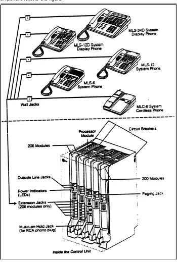
The system’s modular hardware design makes it easy to install and expand. Figure 1-1 shows the components in a basic system. A brief description of each component follows the figure.
Figure 1-1 System Components
Control Unit
The control unit is the heart of the system. It consists of a backplane, a proces-sor module, up to four 206 or 200 modules, and a cover.
■ Backplane. All the system modules slide into the backplane, which chan-nels power to the system.
■ Processor Module. The processor module provides the intelligence that controls most of the system’s features. It also has an RCA jack for a music-on-hold audio source and a jack for a loudspeaker paging system.
■ 206 Module. Each 206 module has jacks to connect a maximum of 2 out-side telephone lines and 6 extensions. You can connect telephones and other telecommunications devices (such as fax machines, answering machines, or modems) to the extension jacks on the 206 module (either directly or through your building’s extension jacks). Each 206 module has a green power indicator that shows when it is turned on. A system can have up to four 206 modules, so the maximum capacity of the system is 8 lines and 24 extensions. The system requires at least one 206 module.
■ 200 Module. The 200 module is similar to the 206 module, but without extension jacks. It only has jacks for two outside lines. This module lets you add lines inexpensively when you do not need more extensions.
■ Cover. The cover slides onto the front of the backplane after all modules have been installed.
Telephones
Two kinds of telephones work with your system:
"MLS” stands for "Multi-Line
Set," because an MLS-model ■ AT&T MLS- and MLC-model phones that are designed to make maximum telephone can handle more than use of the system’s features. In this book these phones are called “system
one outside line. phones.”
"MLC” stands for "Multi-Line
Cordless.” ■ Industry-standard (non-proprietary) rotary or touch-tone phones, including
standard feature phones with built-in feature buttons and lights. In this book these phones are called “standard phones.”
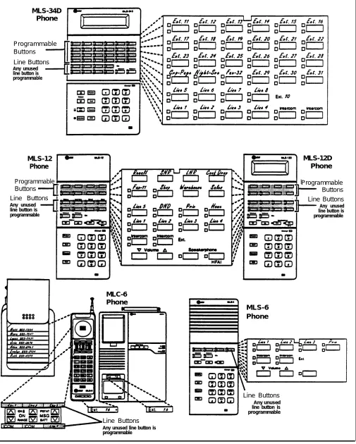
AT&T manufactures the following system telephones:
In order to program the system, ■ you must install an MLS-12D or
MLS-34D phone at extension 10.
AT&T MLS-34D™ Telephone. This phone is a good choice for extension
■
■
■
■
buttons. It also has a built-in speaker and microphone, and a display that shows various status information, including the following:
■ Current date, day, and time
■ Number you dialed (when you make a call)
■ Extension calling you or transferring a call to you (when you receive an inside call)
■ Prompts and messages (when you are changing system settings) ■ Elapsed time (during a call)
AT&T MLS-12D™ Telephone. This phone has 12 buttons with lights: 8
but-tons for outside lines or programmable features, 2 intercom butbut-tons, and 2 lighted programmable buttons. It also has 6 additional programmable but-tons without lights, a built-in speaker and microphone, and a display like the one on the MLS-34D.
AT&T MLS-12™ Telephone. This telephone is the MLS-12D telephone
without a display.
AT&T MLS-6™ Telephone. This telephone has 6 buttons with lights,
includ-ing 4 buttons for outside lines or programmable features and 2 intercom but-tons. It also has a built-in speaker.
AT&T MLC-6 Cordless Telephone. This cordless telephone works like the
MLS-6 corded telephone. It has 6 buttons, including 4 buttons for outside lines or programmable features and 2 intercom buttons, and a display that shows line status. It also includes an On/Off button that you must press before you can use the phone (to save battery power), and some special cordless feature buttons.
Auxiliary Equipment
Industry-Standard Devices
The system works with many telecommunications devices, not only system tele-phones. You can connect almost any industry-standard device to your system, and certain models of other devices, all without expensive adapters or additional phone lines.
For best results, connect any Many types of industry-standard, single-line telecommunications devices will device with more than one Iine as
a single-line device. work with your system:
Limitations
■ Touch-tone and rotary telephones ■ Fax machines
■ Answering machines ■ Modems
■ Credit card scanners ■ Cordless telephones
You can connect almost any standard device to your system, regardless of the manufacturer. The following limitations apply:
■ It must be industry standard and non-proprietary. That is, it cannot be made specifically for use on a particular telephone system. (For example, you can-not connect an AT&T MERLIN® phone because it is specifically designed for use on a MERLIN system.)
Its Ringer Equivalence Number (REN*) cannot be greater than 2.0. (The ■
REN is shown on a label, usually on the bottom of the device.)
Connecting and Using
You can connect a standard device so that it is on an extension by itself, or soStandard Devices
that it shares an extension with another piece of equipment (either anotherstan-dard device or a system phone). For example, you can connect a stanstan-dard touch-tone phone and an answering machine to the same extension. To connect two devices on one extension, you need an inexpensive AT&T 267F2 bridging adapter (two are provided with each 206 module). See Chapter 2 for
installation instructions.
For additional information on programming and using fax machines, answering machines, modems, or credit card scanners, see Chapter 5.
Other Devices
You can connect non-standard devices to your system, but only specific models are compatible with the system. Contact an AT&T sales representative for details. These devices include:
■ Loudspeaker paging systems allow you to broadcast a message over a large area, by connecting the paging system to the control unit processor module. The system supports the AT&T PagePac®
models. For information on how to use a loudspeaker paging system with the system, see Chapter 4.
■ Music-on-hold systems allow you to play recorded music to callers while they are on hold, by connecting the music-on-hold system to the control unit processor module. The system supports the AT&T Magic on Hold®
system and most models from other manufacturers.
■ DoorPhones allow visitors to ring up to 5 extensions at once by pressing a button on the doorphone; the person who answers a doorphone call can then use the phone to speak to the visitor over the doorphone. The system sup-ports up to two AT&T PARTNER Plus doorphones, which can be installed indoors or outdoors. A doorphone is especially useful for providing access to offices or departments after hours. For example, you can install a door-phone outside your building entrance to allow visitors to call selected exten-sions when the receptionist is not there and the front door is locked.
■ Auto attendants answer calls and route them to appropriate extensions based on user responses to recorded messages.
■ Headsets allow users to have private, hands-free conversations. A headset is a combination earphone and microphone worn on the head, useful for receptionists, salespeople, or others who may need to have their hands free while talking on the phone. AT&T sells several headsets.
■ Extra alerts are strobes, lights, chimes, horns, or bells that ring when calls come in. AT&T sells several types of extra alerts.
■ In-Range Out-of-Building (IROB) protectors prevent electrical surges from damaging your system when phones are installed in another building. The system supports the AT&T 503A1 IROB protector. For installation instruc-tions, refer to the booklet packaged with the protector.
■ Speakerphones provide hands-free two-way operation of the phone without lifting the handset. (The MLS-34D, MLS-12D, and MLS-12 phones have built-in speakers and microphones, eliminating the need for a separate speakerphone.) The system supports the AT&T S203 speakerphone when it is combined on an extension with a standard single-line phone.
■
■
Telephone-recording device interfaces allow you to record both sides of
telephone conversations.
Repertory dialers allow you to store frequently used numbers for one-touch
dialing. If you need many speed dial numbers, a repertory dialer can be combined on an extension with a system or standard phone to supplement the system’s capabilities.
Hard-of-hearing handsets are designed for users who need even more
amplification than is provided by the volume controls on system phones. Although the volume controls on system phones significantly reduce the need for an amplified handset, hard-of-hearing users may find that the AT&T ■
K6S handset meets their needs.
Chapter 2 explains how to connect these devices to the system and how to combine them on a single extension.
Ordering Auxiliary Equipment
Auxiliary equipment is available from many AT&T sources. Contact any of the following for sales information and advice on the equipment that would best meet your needs:
Installing the Hardware
2
Important Safety Instructions
Always follow these basic safety precautions when using the system: 1.
2. 3.
4.
5. 6.
7.
Read and understand all instructions.
Follow all warnings and instructions marked on the product. DO NOT block or cover the ventilation slots and openings. They prevent the product from overheating. DO NOT place the product in a separate enclosure, unless proper ventilation is provided.
Never spill liquid on the product or drop objects into the ventilation slots and openings. Doing so may result in serious damage to the components.
Repair or service must be performed by a qualified repair person. The product is provided with a 3-wire grounding type plug. This is a safety feature. DO NOT defeat the safety purpose of the grounding type plug. DO NOT staple or otherwise attach the AC power supply cord to building surfaces.
DO NOT use the product near water or in a wet or damp place (such as a wet basement).
Additional Safety Instructions for Installation Personnel
Install the product to meet all the environmental and electrical requirements listed in the specifications (see Appendix D).
1. DO NOT install telephone wiring during a lightning storm.
2. DO NOT install telephone jacks in a wet location unless the jack is specifically designed for wet locations.
3. Never touch uninsulated telephone wires or terminals, unless the tele-phone line has been disconnected at the network interface.
4. Use caution when installing or modifying telephone lines. 5. The system control unit must be securely wall mounted.
CAUTION:
If any wiring from the extension jacks leaves the building premises, you must install AT&T 503A1 IROB protectors (see Appendix D).
CAUTION:
Use only AT&T-manufactured PARTNER modules in the PARTNER Plus Communications System.
Line and Extension Numbering
The way that you install system modules in the control unit determines the numbering of lines and extensions. The system supports up to eight telephone
After you turn the system on and lines, which connect to the top jacks on 206 or 200 modules in the system’s the internal battery is fully control unit. When you first supply power to the system, it “counts” the 206 or charged (24 hours), the system
will retain all settings for up to 200 modules in the control unit and calculates the number of lines-two lines for four days in the event of a power each module installed. The system then numbers lines from 1 through 8 (if you failure. have the maximum number of lines), as shown in Figure 2-1.
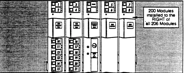
Be sure that the 200 modules are installed to the RIGHT of all 206 modules. Otherwise, your extensions wilI not be consecutively numbered.
Figure 2-1 Line Numbering
For each 206 module, the system assigns six extensions. With four 206 modules, extensions are numbered 10 through 33, as shown in Figure 2-2.
Figure 2-2 Extension Numbering for 206 Modules
If you install 206 modules and 200 modules, the system assigns two lines and six extensions for each 206 module, and only two lines for each 200 module (because 200 modules have no extension jacks). Figure 2-3 shows a system with two 206 modules and two 200 modules; this system has eight lines and twelve extensions (numbered 10 through 21).
Figure 2-3 Extension Numbering for 206 and 200 Modules
An Example System Setup
These two pages shows an example system with two 206 modules and one 200 module, giving it a capacity of 6 outside lines and up to 12 extensions. In the example, system phones and industry-standard equipment are connected to 9 extensions. An ordinary 110 VAC grounded wall outlet (not controlled by an on/off switch) supplies power to the control unit. The circled numbers in the figure refer to the following list, which gives a brief description of the system’s hardware components.
Control Unit
The control unit consists of a backplane, cover (not shown), one processor module, and up to four 206 or 200 modules.
■
■ Backplane. The backplane channels power to the system
and connects the modules together.
Processor Module. The processor module provides most of
the system features. It also has Music-on-Hold and paging jacks.
206 Modules. Each 206 module has jacks for 2 incoming
telephone lines and 6 extensions. The system must have at least one 206 module, and can have up to four, so the maximum system capacity is 8 lines and 24 extensions.
200 ModuIe. The 200 module is similar to the 206 module,
but without extension jacks. You can have up to three 200 modules in the system (installed to the right of all 206 modules). Each 200 module provides 2 additional outside lines but no additional extensions.
Line Jacks. Outside telephone lines connect to the top two
jacks on each 200 or 206 module.
Extension Jacks. Inside wiring for telephones and other
telecommunications equipment connects to the bottom six jacks on each 206 module.
Music-on-Hold Jack. The audio source plugs directly into
this jack. You can connect any type of audio equipment to your system (including a CD player, cassette player, stereo receiver), but you must supply an audio cord with an RCA phono plug. In this example, AT&T Music On Hold is connected directly to the Music-on-Hold jack on the proces-sor module to provide customized music and messages for callers on hold. For information on Music on Hold, call your AT&T representative or call the AT&T Sourcebook at 1 800 451-2100.
PAGE Jack. The loudspeaker paging system plugs directly
into this modular jack on the processor module. Your phone system is compatible with AT&T’s PagePac paging systems. The PagePac6 is shown here.
Network lnterface Jacks. These jacks provide access to
telephone lines coming from the local telephone company or from another system, such as a PBX (Private Branch Ex- change) or Centrex system. To connect each outside line to your system, plug one end of a line cord into one of these jacks and the other end into a line jack on a 200 or 206 module.
Extensions
This example system shows various devices—including both system telephones and industry-standard devices—connected to each extension. System extensions connect to the extension jacks in the control unit by way of your building’s inside wiring.
Extension 10: The following devices are on extension 10:
■ MLS-34D Display Phone. In this example, the receptionist
on extension 10 has a 34-button display phone. This phone can handle 8 outside lines. You can also program all extensions on your system as Auto Dial buttons (see
Chapter 3), to show the status of up to 24 extensions. To program the system or system telephones from extension 10, you must use a system display phone (MLS-34D or MLS-12D). The display on these phones shows the date, day, time, number dialed, duration of calls, and program-ming messages.
AT&T 267F2 Bridging Adapter. This adapter lets you
connect two devices—in this example an MLS-34D display phone and a standard touch-tone phone on one exten-sion jack. The adapter has two modular jacks, one for each phone. The bridging adapter plugs into a wall jack or directly into an extension jack on the 206 module.
Standard Touch-Tone Telephone for Power Failure Operation. In the event of a power failure, the first
exten-sion jack on each 206 module connects to the first outside line on that module, to provide continuous service to standard telephones. In this example, the MLS-34D phone on extension 10 will not work during a power failure. However, the receptionist can use the standard touch-tone phone connected to extension 10 to place and answer calls on line 1.
Extension 11: MLS-12 Telephone. This 12-button system
phone has the same controls as the MLS-12D telephone (see extension 16), but it has no display.
Extension 12: MLS-6 Telephone and Answering Machine.
using a 267F2 bridging adapter, both a 6-button system phone and an answering machine are connected to one extension. The MLS-6 phone accommodates up to 4 outside lines.
Extension 13: Industry-Standard Telephone. A standard
single-line touch-tone phone (such as you might have in your home) is connected directly to the extension jack.
Extension 14: Doorphone. A doorphone is installed at the
entrance. When someone at the entrance presses the button on the doorphone, up to 5 designated telephones in the office ring automatically.
Extension 15: Bell. A loud bell is connected directly to the
extension jack.
Extension 16: MLS-12D Display Phone. In this example,
extension 16 has a 12-button display phone. This phone can handle 8 outside lines and has a display showing the date, day, time, number dialed, duration of calls, and programming messages. Also, its programmable buttons (two with lights) can store additional features and Auto Dial numbers.
Extension 17: Fax Machine and Standard Telephone. A
fax machine and standard touch-tone phone are connected together on an extension jack. This setup lets you share the fax line with a telephone.
Alternatively, you can use a system phone at another extension to monitor the fax machine (Fax Management). To do so, first use System Programming to identify the fax machine extension. Then program a lighted button on the system phone with the fax extension as an Auto Dial number. You can then use the Auto Dial number to quickly transfer calls from that extension to the fax machine. In addition, the light on that button shows whether the fax machine is in use, busy, returning a call you transferred to it, or not answering calls. If your AT&T fax machine includes the Notify feature, the fax machine can also notify you when a fax has been received.
Extension 18: 6 Cordless Telephone. An AT&T
CONTROL UNIT
NOTE:
This sample system has six lines (1-6) and nine extensions (10-18)
①
②
④
Backplane
Processor Module (center slot)
③
206 Modules200 Module (installed to the right of all 206 modules)
⑤
Line Jacks⑥
Extension Jacks⑧
PAGE Jack (connectedto AT&T PagePac®
6 Paging System)
⑦
Music-on-Hold Jack(connected to AT&T Magic on Hold® deck)
⑨
Network Interface Jacks
EXTENSIONS
Extension 10
Extension 18 MLC-6
267F2 Bridging Adapter
Cordless Phone
Standard Phone for Power Failure
Operation Extension 17
MLS-34D Display
Phone 267F2Bridging
Adapter Fax Machine
Extension 11 Standard
Touch-Tone Telephone MLS-12
System Phone
Extension 16
267F2 Bridging Extension 12 Bell
Adapter Extension 15
Answering Machine
MLS-12D
Extension 13 Extension 14 Display
Phone MLS-6
System Phone
Standard Doorphone
Touch-Tone Telephone
Installing the Control Unit
Before you begin, use the System Planner to decide where phones and other equipment are to be installed, and how the system and phones are to be pro-grammed. Instructions for installing the control unit, telephones, and other equipment are on the following pages.
CAUTION:
Enviromental and electrical conditions must meet the specifications in Appendix D.
CAUTION:
Do not connect the AC power cord before you install modules in the backplane.
Installing the Backplane and System Modules
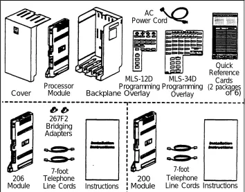
Before installing the backplane and system modules, be sure you have the parts shown in Figure 2-4 (if not, call the Helpline). Depending on the number of lines and extensions in your system, you will have up to three packages of system components; Figure 2-4 shows the contents of each package in an area marked by a dashed line.
AC Power Cord
MLS-12D MLS-34D
Processor Programming Programming
Cover Module Backplane Overlay Overlay
Quick Reference
Cards (2 packages
of 6)
7-foot 206
Module
267F2 Bridging Adapters
7-foot Telephone
Line Cords Instructions
200 Module
Telephone
Line Cords Instructions
Figure 2-4 System Parts
Wall mounting is required.
Mount the backplane on the wall, leaving at least 6 inches clearance at the top and sides and 2 feet at the front and bottom. When using the supplied 7-foot cords, install within 5 feet of an electrical outlet not controlled by a switch and the network interface jacks. Hold the backplane against the wall... Using the four screw keyholes in the backplane as a template, mark screw locations on the wall. Start four #12 screws, leaving the screw heads approximately 1/4” away from the wall. Use screws appropriate for the wall surface—when loaded with five mod-ules, the control unit weighs 27.5 pounds. Slip the backplane onto the screws and tighten them.
A Slide the first 206 module into
the leftmost slot of the backplane. (The system will not work if a 206 module is not installed in this slot.) Push slowly but firmly until the module locks into place with two snaps, so that it is attached to the rear of the backplane and held in place by the locking tab on the bottom front of the slot. Do not force the module. If it does not insert easily, remove the module as shown in step 2B, clear any obstruction, and reinsert. Insert the next module in the second slot from the left, aligning the dovetails between the modules. Insert the processor module in the center slot and remaining modules from left to right, without skipping slots.
A Connect the AC power cord. B Check all green lights on the front of
the unit. If any lights are out, check to be sure all circuit breakers are pushed in (see step 5 on page 2-6), then remove the power cord and reseat the module.
LINES
EXTENSIONS
Label the line and extension
B To replace a system module, first
disconnect the AC power cord from the wall outlet, then slide the control unit cover off the backplane.
Place one hand on top of the module. With the other hand, grip the plastic
bracket on the bottom front of the module,and use one finger to hold down the locking tab just below the bracket. Slide the module straight out being careful not to strain the wires connected to the module. (If there is not enough slack in the wires, label and disconnect them before removing the module.)
Disconnect the wires from the old module and plug them into the same jacks on the new module. (Transfer the wires one at a time, to make sure that you know where each wire goes.) Insert the new module as in step 2A.
WARNING:
There are no customer-serviceable components inside the system modules
jacks as shown above. backplane. Hazardous
voltages within. DO NOT OPEN THE MODULES!
Connecting Lines and Extensions
A Connect telephone cords to Test the lines. Plug a system A Connect modular line cords to line jack on modules, starting with the phone into extension 10. Press the Iine 206 module extension jacks, starting at top line jack on leftmost 206 module.
B Route cords through bracket at
bottom of module. Leave at least 2 feet of slack in cords so that you can easily reconnect cords during replacement. Connect free end of each line cord to the appropriate network interface jack. NOTE:
Test for dial tone at network interface jacks before connecting outside Iines.
TO install an (optional) paging system, use a two-pair cord. Insert the
modular plug for the paging system into the jack labeled PAGE on processor. Route cord as for line and extension cords, then connect to loudspeaker paging system.
To connect an audio source, insert an
RCA plug into the Music-on-Hold jack
button for each outside line and listen for dial tone. Repeat for extensions 16, 22, and 28 (if available). Disconnect power before continuing.
NOTE:
Only the steps for connection to the control unit are included here. Follow the manufacturer’s directions for setting up and using your music-on-hold or paging system.
cords, then connect the cord to the audio source. To adjust volume, see the inset illustration in step 4. First use a flathead screwdriver to turn the volume control on the processor counterclock-wise to the lowest setting, then connect AC power as in step 5. Place a call on hold and Iisten while adjusting volume. If you do not hear music at any setting, check system programming procedure
top the jack on the leftmost module.
B Route cords through the hook on front
of the module, then through the slot between module and base of backplane. Leave at least 2 feet of slack to allow easy replacement of system modules. Connect each cord to a wall jack for an extension. NOTE:
If extensions are not wired to modular jacks, call a qualified service technician.
Connect AC power cord. Press firmly into power jack on top right rear of backplane until it locks into place. Make sure circuit breakers on the backplane and modules are pushed in. Plug the other end of the cord into a grounded 3-prong wall outlet not controlled by a switch.
Installing Phones and Devices
Guidelines
System Phones
Industry-Standard
Devices
Combination Extensions
System phones require at least 2-pair wiring and are compatible with AT&T 4-pair SYSTIMAX™ wiring. If you need a shorter cord, use AT&T’s 2-foot D4BU-29 mounting cord (available separately—see “Product Ordering Information” in Appendix C). Connect an MLS-12D or MLS-34D phone to extension 10 for system programming. (See page 2-9 for instructions on assembling system phones.)
Industry-standard equipment (including standard phones) requires 1-pair mounting cords; AT&T D2R mounting cords are recommended.
You can connect an industry-standard device (such as a standard phone or a fax machine) on an extension by itself, or you can use an AT&T 267F2 bridging adapter only combine it with another standard device or a system phone (see Figure 2-5). You cannot install two system phones on the same extension, and the combined REN of two devices on an extension must be no more than 2.0.
Wall Jack
Power Failure Operation
Out-of-Building
Installations
Fax Machines
Doorphones
Hotlines
2 6 7 F 2 Adapter Standard Device Only
System Phone or Standard Device
Figure 2-5 Connecting Two Devices on an Extension
During a power failure, system phones will not work because they require power to operate. However, if a standard phone is connected to extension 10, 16, 22, or 28, it can place and answer calls on lines 1, 3, 5, and 7, respectively. Connect a standard phone to one or more of these extensions, either alone or combined with a system phone. If you combine a standard phone and system phone on one extension, you may want to turn off the standard phone’s ringer during normal use.
Installing phones in a different building from the control unit requires AT&T 503A1 In-Range Out-of-Building (IROB) protectors to prevent damage due to lightning (installation instructions are included with the protector).
If you install a fax machine, use System Programming (#601) to identify the fax extension (see Chapter 3). See Chapter 5 for advice on setting up fax machines.
Do not connect doorphones to extensions 10, 11, 16, 17, 22, 23, 28, or 29. Use System Programming (#604-#606) to identify the doorphone and alerting exten-sions.
A hotline phone must be a standard phone—not a system phone—but it can ring any type of phone. DO not connect a Hotline phone to extensions 10, 16, 22 or
28, to keep them available for power failure use. Use System Programming (#603) to identify the hotline and alerting extensions.
Installation Instructions
Assemble a standard phone or Plug the telephone cord into a other industry-standard device
accord-ing to the manufacturer’s instructions.. (For system phones, see "Assembling System Phones" on page 2-9.) NOTE: To connect devices to the system, follow only these instructions, not the instructions provided by the manufacturer.
To put the button sheet on a system phone, remove the clear plastic cover from the phone—gently pull the center tab down (toward the front of the phone), then lift. Place a filled-out button label sheet on the phone so the holes on the sheet fit over the buttons. Replace the plastic cover.
modular wall jack or directly into a 206 module extension jack. To install two devices on a single extension, see Figure 2-5 on page 2-7.
If the telephone cord provided with a standard device is loose, use an AT&T D2R mounting cord instead.
Test the telephone for proper operation. To test the power and lights on a system phone, press and hold the [#] button for 5 seconds. Before releasing the [#] button, lift the handset. All lights should light, the ringer should sound, and (on the MLS-12 or MLS-34D phones only) a test pattern should appear on the display. If not call the Helpline at 1 800 628-2888. Replace the handset; the phone is now in normal operating mode.
To test the intercom, lift the handset and press an intercom button. You should hear an intercom dial tone. If not, see "Troubleshooting" in Appendix C. Next, test the outside line connection. Lift the handset and press an outside Iine button. You should hear an outside dial tone. If not, see "Troubleshooting" in Appendix C.
Assembling System Phones
Desk Mounting (Stand Required for MLS-34D)
A Plug one end of the handset To install the telephone stand, Slide the Quick Reference card gently place the phone upside down
with the low end of the phone to your
under the phone. cord into the jack on the handset and
the other end into the small jack on the left side on the bottom of the phone.
B Plug one end of the phone cord
into the big jack on the bottom of the phone. Push the cord in place along the channel on the bottom of the phone.
right. Insert the tab on the narrow end of the stand into the right slot on the bottom of the phone. Then insert the other tab into the left slot pushing the stand down and slightly inward until the tab locks into place.
NOTES:
If you wall mount a display phone, the display may be difficult to read, so desk mounting is recommended.
Position MLC-6 cordless system phones at least 20 feet away from the control unit.
Wall Mounting (Stand Required)*
Reverse the plastic hook that sits Install the telephone stand. To in the earpiece part of the handset
cradle.
Insert the phone cord through the snap the stand onto the bottom of the
phone, gently place the phone upside down with the low end of the phone to your right. Insert the tab on the narrow end of the stand into the left slot on the bottom of the phone. Then insert the other tab into the right slot, pushing the
center of the stand and plug it into the jack on the bottom of the phone, then plug the other end into the modular wall jack. Push any excess cord into the space inside the stand, then mount the phone on the wall jack using the screw keyholes on the bottom of the stand. For
CAUTION:
Do not unscrew the bottom of the phone. To do so will expose you to a risk of
eletri-cal shock. stand down and slightly inward until the
proper mounting, the wall jack must be tab locks into place. an AT&T 630B connecting block. Finally,
connect the handset cord as described in "Desk Mounting." step 1A.
*These wall mounting instructions apply to corded MLS-model phones only. To wall mount an MLC-6 cordless phone, follow the instructions in the
Installation and Troubleshooting booklet provided with the phone.
Programming
Procedure
Alphabetical List of System and Telephone Programming Procedures
For information on a programming procedure, see the page cited in this table. System programming procedures are identified by the procedure code following the procedure name (for example. #305 for Abbreviated Ringing). Telephone programming procedures show only the procedure name.
Page Procedure Page
Abbreviated Ringing #305 3-15 Lines, Number of #104 3-14
Allowed List Assignments #408 3-16 Loudspeaker Paging 3-23 Allowed Phone Number Lists #407 3-16 Message Light Off 3-23
Attendant/VMS Extensions #607 3-17 Message Light On 3-23
Auto Dialing 3-22 Music On Hold #602 3-17
Automatic Extension Privacy #304 3-15 Night Service Button #503 3-17 Automatic Line Selection 3-22 Night Service Group #504 3-17
Call Pickup 3-23 Number of Lines #104 3-14
Calling Group Extensions #502 3-17 Outgoing Call Restrictions #401 3-16
Conference Drop 3-23 Outside Conference #109 3-14
Conference, Outside #109 3-14 Password, System #403 3-16
Copy Settings #399 3-15 PBX/Centrax Mode #721 3-14
Date, System #101 3-14 PBX Dial-Out Code #106 3-14
Day, system #102 3-14 Personal Speed Dial Numbers 3-22
Dial mode #201 3-15 Pickup Group 3-23
Disallowed List Assignment #405 3-16 Pickup Group Extensions #501 3-17
Disallowed Phone Number Lists #404 3-16 Privacy 3-23
Display Language #303 3-15 Privacy, Automatic Extension #304 3-15
Do Not Disturb 3-22 Recall 3-22
Doorphone 1 Extension #604 3-17 Recall Timer Duration #107 3-14
Doorphone 2 Extension #605 3-17 Reset #728 3-14
Doorphone Alert Extensions #606 3-17 Restricton, Line Access #302 3-15 Drop, Conference 3-23 Restrictions, Outgoing Call #401 3-16 Emergency Phone Number List #406 3-16 Ringing, Abbreviated #305 3-15
Exclusive Hold 3-22 Ringing, Line 3-22
Fax Machine Extensions #601 3-17 Rotary Dialing Timeout #108 3-14
Group Calling 3-23 Save Number Redial 3-22
Group Paging 3-23 SpeedDial Numbers, Personal 3-22
HoId Disconnect Time #203 3-15 Speed Dial Numbers, System 3-18
Hotline #603 3-17 System Password #403 3-16
Language, Display #303 3-15 System Speed Dial Numbers 3-18
Last Number Redial 3-23 Time, System #103 3-14
Line Access Restriction #302 3-15 Toll Call Prefix #402 3-16
Line Assignment #301 3-15 Touch-Tone Enable 3-23
Line Ringing 3-22 Transfer Return Extension #306 3-15
Line Selection, Automatic 3-22 Transfer Return Rings #105 3-14
Overview
After you install the system hardware as described in Chapter 2, you can customize the system control unit and telephones to meet the requirements of your business. This chapter explains how to use programming to customize your system.
There are two types of programming:
■
■
System Programming defines how the control unit will work with the
telephones and other devices connected to it. When the system is first installed, it uses factory settings that reflect the most common settings, which you can change as needed. The “System Programming Options” section in this chapter explains your choices.
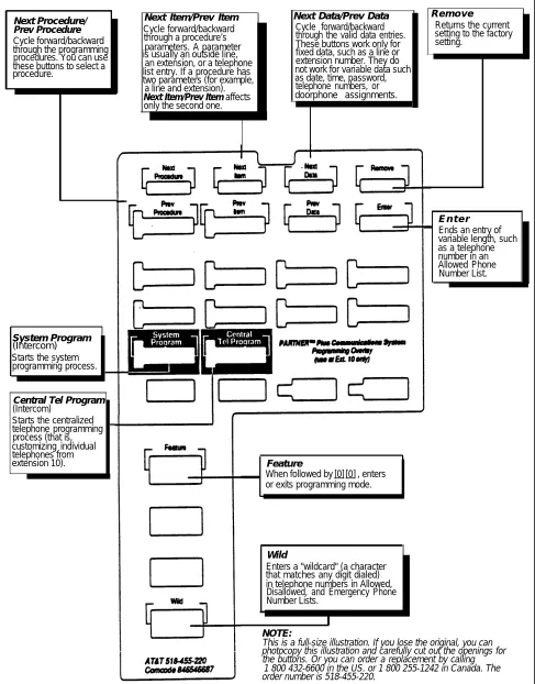
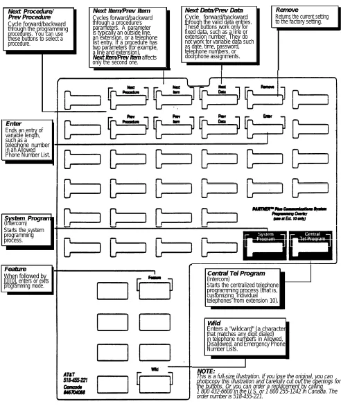
You program the system from extension 10, using an MLS-34D or MLS-12D phone, with the appropriate programming overlay placed on top of the phone.
System Programming procedures are identified by # and a three-digit code (for example, System Date is #101). A complete list of programming
procedures, including brief descriptions and factory settings, is on the inside back cover of this book. Descriptions and step-by-step programming instructions are in the “System Programming Procedures” section in this
chapter.
Telephone Programming further customizes the individual telephones in the
system. For example, you use telephone programming to define how the phone at an extension will ring and to store calling features on the
programmable buttons of a system telephone, so that a user can access a feature by pressing a single button.
Telephone programming can be performed in two ways:
■ From extension 10 using an MLS-34D or MLS-12D phone; this is called Centralized Telephone Programming.
Users with system phones can also program their own telephones (this is ■
called Extension Programming).
For more details on programming telephones, see the “Telephone Programming” section in this chapter.
Initial System Setup
When first installing the system hardware, you must perform the following procedures to setup your system:
■ Dial Mode (#201) identifies any rotary lines in your phone system.
Other programming procedures are optional, but strongly recommended if you want to make the most of your investment. See “System Programming Options” in this chapter for details.
Changing Settings after Installation
■
■
■
■
If you want to give a new exten- ■
sion the same settings as a pre-viously programmed extension, you can use the Copy Settings procedure (#399) to copy the set-tings to the new extension. See "Telephone Programming Pro-cedures" in this chapter for details.
If your system was programmed to meet your requirements at the time it was installed, you may still want to change those settings occasionally as the needs of your business change. The following settings are typically changed periodi-cally:
Changing the System Clock. You may need to change or reset the system
clock for daylight saving time, after a prolonged power failure, or after a complete system reset. To change the system clock, use the following pro-cedures:
■ System Date (#101). Sets the month, day, and year. ■ System Day (#102). Sets the day of the week. ■ System Time (#103). Sets the hour.
Changing to PBX or Centrex Service. If your system operates behind a
PBX or Centrex system, you can use PBX/Centrex Mode (#721) to customize your system for Centrex operation (see Appendix A for details).
Changing to Rotary or Touch-Tone Service. See procedure #201 (Dial
Mode).
New Lines. If you add an outside line to your system after installation, use
one or more of the following procedures:
■ Dial Mode (#201) identifies the new line as rotary or touch-tone. ■ Line Assignment (#301) assigns the line for a particular extension. ■ Line Ringing (Centralized Telephone Programming) specifies how the
line rings on a particular extension.
■ Line Access Restriction (#302) restricts call activity on the line for a par-ticular extension.
New Extensions. If you add an extension to your system after installation,
use one or more of the following procedures:
■ Line Assignment (#301) assigns specific lines to the extension. (The factory setting is for all lines to be available on all extensions.)
■ Line Access Restriction (#302) restricts call activity on specific lines assigned to the extension.
■ Outgoing Call Restriction (#401) specifies the type of outgoing calls the extension is allowed to make.
■ Disallowed List Assignment (#405) assigns a Disallowed Phone Number list to the extension. Use the Disallowed Phone Numbers Lists (#404) procedure to compile lists of outside numbers that extensions can-not dial.
■ Allowed List Assignment (#408) assigns an Allowed Phone Number list to the extension. Use the Allowed Phone Numbers Lists (#407) procedure to compile lists of outside numbers that extensions can dial.
■ Group Assignment procedures let you assign an extension to the Pickup Group (#501), Calling Group (#502), or Night Service Group (#504). ■ Auxiliary Equipment Extension procedures let you identify any
exten-sion on which you have installed a fax machine (#601), doorphone (#604—#606), or auto attendant (#607).
■ Automatic Extension Privacy (#304) prevents anyone from joining a call at the extension. It is typically used for an extension connected to a modem, fax, or credit card scanner—any device whose function can be disrupted by someone attempting to join it. (To program Privacy onto a system phone button, so that it can be turned on and off, see “Telephone Programming Procedures” at the end of this chapter.)
■ Display Language (#303) specifies the language (English, French, or Spanish) to appear on system display phones (MLS-34D or MLS-12D). ■ Automatic Line Selection (Centralized Telephone Programming)
specifies the order in which the system tries to select an available line (intercom or outside) when the user lifts the handset to make a call. ■ Line Ringing (Centralized Telephone Programming) specifies how each
System Programming
Read this section before programming your system. "System Programming Options" explains the choices that are available to you; "System Programming Procedures" explains how to perform each System Programming procedure.
System Programming Options
Dialing Restrictions and
Permissions
These two procedures control an extension's access to an outside line. Once an extension is on an outside line, what it can dial is controlled by Outgoing Call Res-trictions and Disallowed Phone Number Lists (see page 3-5).
This section explains how you can set up your system to operate most efficiently, taking into account your company’s telephone service, personnel, and equipment, as well as the special needs of any particular department.
The system has several procedures for restricting telephone use, and several used for overriding those restrictions. You can use any combination of these procedures to design a system that meets your needs.
NOTE:
While procedures that restrict dialing are very effective, absolute protection against misuse cannot be guaranteed. System phones give more protection than standard phones. Therefore, we strongly recommend that you install sys-tem phones where restricting phone use is important.
Restricting Access to Outside Lines
Two programming procedures control an extension’s access to outside lines:
■
■
Line Assignment (#301) assigns lines to an extension. If a line is not
assigned, the extension cannot normally make any calls on the line.
Line Access Restriction (#302) partially blocks an extension’s access to a
certain line. For example, you may want a secretary to answer calls on a manager’s line, but not to make any outgoing calls on the line; in this case you can set the manager’s line on the secretary’s extension to “incoming only.” The following choices are available:
■ NO restrictions.
■ Outgoing only. The extension cannot receive calls on the line (except transferred calls), but can make outgoing calls.
■ Incoming only. The extension can receive but not make calls on the line. If you restrict a line on an extension to incoming calls only, the user can-not select that line to dial out.
■ No access. The extension can see the status of the line (by looking at the lights), join a call, and pickup a transferred or held call. However, the extension cannot make or receive calls on the line.
Controlling Calls on Outside Lines
When an extension is allowed access to an outside line, you can use the follow-ing procedures to control callfollow-ing:
■
■
■
Outgoing Call Restrictions (#401) controls calling for all lines available on
an extension. You have the following choices:
■ No restrictions allows long distance, local, and inside calling.
■ Local only allows local and inside calling only (make sure the Toll Call Prefix is set properly, using procedure #402).
■ Inside only allows intercom calls only.
Disallowed Phone Number Lists (#404) creates lists of numbers that
can-not be dialed. The numbers on a disallowed list can be entire telephone numbers or numbers of a certain type (such as all numbers in a particular area code, such as all 900 numbers). You can store as many as four different lists of up to 10 numbers each.
After you create the Disallowed Phone Number lists, use the Disallowed List Assignment (#405) procedure to assign one or more of the lists to a specific extension. When a Disallowed Phone Number list is assigned to an exten-sion, the list applies to all the lines on that extension.
Night Service causes after-hour calls to ring immediately at the extensions
in the Night Service Group, regardless of line ringing during normal day operation. If you define a system password, turning Night Service on also restricts outside calling by all extensions in the Night Service Group. See page 3-8 for details on Night Service.
■
Overriding Dialing Restrictions
The following programming procedures provide ways to override all dialing res-trictions, except those imposed by Line Access Restriction (#302):
■
Emergency Phone Number List (#406) defines a list of up to 10 numbers
that any extension in the system can dial (if it has access to an outside line). A typical example is 911.
Marked System Speed Dial Numbers can be dialed by any extension with
access to an outside line. Speed Dial numbers are outside telephone numbers that a user can dial automatically by pressing [Feature] (or [#] on a standard phone), followed by a two-digit code. Marking a System Speed Dial number lets any user in the system dial it, overriding any dialing restric-tions for the extension.
System Password (#403) creates a password that, when entered at any
The following procedure can be used to override all dialing restrictions except Night Service with a System Password and Line Access Restriction:
■ Allowed Phone Number Lists (#407) allows you to create lists of numbers that specific extensions are allowed to dial. Even if an extension’s settings for Outgoing Call Restrictions and Disallowed Phone Numbers would nor-mally prevent the extension from dialing a number, defining the number as an Allowed Phone Number lets the extension dial it. (For example, if you put 900 numbers on a Disallowed list but want users to be able to call a specific 900 technical support hotline, put that number in an Allowed list.) The sys-tem stores as many as four different allowed lists of up to 10 numbers each. After creating allowed lists, use the Allowed List Assignment (#408) pro-cedure to assign one or more of the lists to a specific extension.
NOTES:
1. Users can always place and receive intercom calls and can always receive transferred calls, regardless of the dialing restrictions placed on an extension.
2. There are a variety of factors that influence the effectiveness of dialing res-trictions. Avoid putting 800 numbers in your Emergency list. If you need to allow restricted users to access 800 numbers, put those numbers in an Allowed list.
Summary
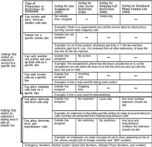
Table 3-1 on the next page summarizes the available dialing restrictions and permissions, showing how they can be combined in a variety of ways to custom-ize an extension’s dialing privileges.
Extension
Settings that restrict an extension’s access to a specific line
Settings that restrict an extension’s dialing once it gets an outside line
Type of Setting for Setting for
Permissions or Setting for Line Line Access Outgoing Call Setting for Disallowed Restrictions for Assignment Restriction Restrictions Phone Number List
(#301) (#302) (#401) (#404)
Can receive and No outside Inside only place intercom lines assigned
(inside) calls only
Example: Clerks in a supermarket can call the service desk to check prices, but they cannot make outgoing calls.
Cannot use a Outside line not specific outside line assigned
Example: On an 8-line system, all phones get lines 1-7: the fax machine extension gets line 8. Line 8 is removed from all other extensions, to keep the line free for the fax machine.
Can only monitor Outside line No access call activity and pick assigned
up held calls on a
Example: The receptionist’s phone has the boss's private line on it, so the
specific line
receptionist can see when the boss is on the line and can pick up calls the boss has put on hold.
Can only receive Outside line Incoming calls on a specific assigned only line
ExampIe: A line is only used for taking sales orders.
Can place outgoing Outside line Outgoing calls only on a assigned only specfic line
Example: A line is only used for telemarketing.
Can place intercom Outside line No restriction Local only Any local numbers and local calls only assigned extension should not
dial
Example: An extension in the lobby permits visitors to make local and intercom calls, but they are prevented from making long-distance calls.
Can place intercom, Outside line No restriction No restriction Any local and
local, and assigned long-distance
long-distance calls numbers the extension
should not dial
Example: An employee can make any type of call on lines appearing on his or her phone, except calls to foreign countries and "900" numbers.
Emergency Numbers, Marked System Speed Dial Numbers, Allowed Phone Numbers, and numbers dialed using the System Password overide all dialing restrictions if a user has access to an outside line to dial the call.
Setting Up Groups of
You can set up three types of extension groups: a Pickup Group that lets anyExtensions
user in the system answer calls for any extension in the group, a Calling Groupthat lets users ring or page all extensions in the group simultaneously, and a Night Service Group that receives calls after hours.
Night Service
Pickup Group
The Pickup Group feature allows you to create one group of extensions in which
any outside call ringing at an extension in the group can be answered from any other extension in the system by dialing a special code. In other words, when an outside call rings in the Pickup Group, you can answer that call from any extension (regardless of whether that extension is in the group or what type of phone you are using) by dialing the code.
The Pickup Group is typically used for a group of people who can handle each other’s incoming calls.
Example: A group of typists work in a large room separated by cubicles. If any
one of the typists is away from his or her desk, anyone can answer an incoming call (without knowing whose phone is ringing) simply by dialing [Intercom] [6] [6] (the Pickup Group dial code). Another way to use this feature is to put all exten-sions in the Pickup Group. This allows anyone on the system to answer any ringing phone.
Pickup Group Extensions (#501) assign extensions to the Pickup Group.
Calling Group
The Calling Group feature allows you to make an intercom call—either ringing or voice-signaled—to an entire group of extensions simultaneously. If one exten-sion in the group answers the call, the ringing stops at the other extenexten-sions in the group.
Example: A car dealership puts all extensions for the sales group into
the Calling Group. To talk to any salesperson, the sales manager simply places an intercom call to the Calling Group by dialing [Intercom] [7] [1] , the Calling Group dial code. All the phones in the group would ring, and the sales manager would be connected to the first salesperson to pick up. (Alternatively, the sales manager could page (voice signal) the group through their system phones’ speakers by dialing [*] [7] [1] instead.)
Calling Group Extensions (#502) assign extensions to the Calling Group. You
can create one Calling Group. Exclude extensions with fax machines, hotline phones, or doorphones from the Calling Group.
The Night Service feature allows you to change how a group of extensions operate after normal business hours. When Night Service is turned on, all
incom-ing calls will rincom-ing immediately at all extensions in the Night Service Group, even if Line Ringing for those extensions is set for “delayed ring” or “no ring” during normal daytime use.
Three procedures are used to program Night Service:
■ Night Service Button (#503) programs the Night Service On/Off feature onto a specific programmable button on the system display phone at extension 10
Night Service Button
Setting Up Auxiliary
Equipment
"System Programming Pro-cedures" later in this chapter vides information on the pro-gramming procedures discussed in this section. In addition, Chapter 5, "Using Auxiliary Equipment," gives advise on ins-talling and using fax machines, modems, and credit card scanners.
only (see Figure 3-1 for the location of the button). Press the button to turn
Night Service on or off. (You must assign a Night Service button before you
can use the Night Service feature.)
Example: In a real estate office, all calls normally come through a
reception-ist. The receptionist goes home at 5:00 in the evening, but some agents work later. At 5:00, the receptionist turns on Night Service, so all phones in the Night Service Group ring immediately when a call comes in.
MLS-12D MLS-34D
Figure 3-1 Location of Night Service Button
■ Night Service Group (#504) assigns extensions to the Night Service Group. ■ System Password (#403) (optional) identifies the system password. If a
password is programmed, you must enter it to turn Night Service on or off. If Night Service is on and a password has been programmed, extensions in the Night Service Group must enter the System Password before dialing outside telephone numbers (except Emergency Numbers and Marked System Speed Dial numbers).
In addition to telephones, your system can include fax machines, answering machines, auto attendants, modems, doorphones, loudspeaker paging sys-tems, and other kinds of auxiliary equipment that use telephone lines.
The following programming procedures help you manage auxiliary equipment:
■ Fax Machine Extensions (#601) lets you identify an extension on which a fax machine is installed. If you also program that extension number as an Auto Dial button on a system telephone, and the button has a light, the but-ton will show the status of the fax machine. If the light is on, the fax is in use, is returning a transferred call, or needs paper.
■
A hotline phone must be a stan-dard rotary or touch-tone tele-phone (not a system tele-phone).
■
Music on Hold (#602) activates or deactivates the Music-on-Hold jack on
the processor module.
Hotline (#603) allows you to create a Hotline extension. Lifting the handset
on a Hotline extension automatically makes an intercom call to another predetermined extension.
Example: A supermarket installs a Hotline phone at its meat counter. When
a customer lifts the Hotline phone’s handset, the butcher’s phone rings.
When programming a Hotline, yoU should also perform these procedures:
■ Automatic Line Selection for the Hotline extension must be programmed to Intercom only.
■ Line Assignment (#301) makes sure that no outside lines are assigned to the Hotline extension.
Doorphone Extensions (#604 and #605) identify the extensions on which
doorphones are installed. Doorphone Alert Extensions (#606) identifies the extensions that ring when the button on a doorphone is pressed. A single extension cannot be both a doorphone and a hotline phone.
Auto Attendan/VMS Extensions (#607) identifies extensions on which you
■
■
have installed an auto attendant. Auto attendants answer calls and route them to the appropriate extension based on caller responses. Also, use