18th International Conference on Structural Mechanics in Reactor Technology (SMiRT 18) Beijing, China, August 7-12, 2005 SMiRT18-C07-2
A MODEL FOR DELAYED HYDRIDE CRACKING OF ZIRCONIUM
ALLOYS
Young S. Kim
Korea Atomic Energy Research Institute
150, Dukjin-dong, Daejeon, Korea,
305-353
Phone: 82-42-868-2359
Fax:82-42-868-8346
E-mail: [email protected]
Sang B. Ahn
Korea Atomic Energy Research Institute
150, Dukjin-dong, Daejeon, Korea,
305-353
Phone: 82-42-868-8454
Fax: 82-42-868-8346
E-mail: [email protected]
Kang S. Kim
Korea Atomic Energy Research Institute
150, Dukjin-dong, Daejeon, Korea, 305-353
Phone: 042-868-4749
Fax: 82-42-868-8346
E-mail: [email protected]
ABSTRACT
A new model for delayed hydride cracking (DHC) of zirconium alloys is proposed where its driving force is not the stress gradient but a supersaturated hydrogen concentration or ∆C resulting from a hysteresis of the terminal solid solubility of hydrogen in zirconium upon heating and cooling. For the feasibility of the newly proposed DHC model, the DHC tests were conducted on a cold-worked Zr-2.5Nb tube with a hydrogen concentration of 12 to 100 ppm where a tensile stress was applied at different times of a thermal cycle. The delayed hydride cracking velocity (DHCV) increased with an increase in the supersaturated hydrogen concentration, ∆C and then leveled off to a constant value at the ∆C in excess of the ∆Cmax, corresponding to a
difference of the terminal solid solubility of the hydrogen on cool-down and on heat-up. The applied tensile stress was found to promote precipitation of reoriented hydrides in the plastic zone ahead of the crack tip, developing the ∆C between the bulk region and the crack tip. With the reoriented hydrides precipitated all over the cross section of the specimen on cooling, however, no DHC occurred due to disappearance of the ∆C. Constant DHCV of zirconium alloys independent of an applied stress intensity factor, K is discussed with the new DHC model.
Keywords: Delayed hydride cracking velocity, zirconium, Zr-2.5Nb, terminal solid solubility, supersaturated hydrogen concentration.
1. INTRODUCTION
One unique feature of delayed hydride cracking (DHC) of zirconium alloys is a constant crack growth rate independent of applied stress intensity factors at the second stage where the applied stress intensity factor far exceeds the critical stress intensity factor, KIH required to initiate DHC. (Coleman, 1977). Furthermore, this
processes such as DHC, HE and SCC. The aim of this work is to review the feasibility of the existing DHC models and propose a new DHC model which can contribute to a better understanding of the DHC behavior of zirconium alloys including a constant DHCV independent of the applied stress intensity factors at the 2nd stage.
2. DRIVING FORCE FOR DHC 2.1. Existing DHC models
Dutton (1977) and Puls (1982) suggested a DHC model where under a tensile stress gradient, hydrogen moved from the bulk region to the crack tip due to the effect of tensile stress on the terminal solid solubility of hydrogen arising from the difference in the molar volume of the hydrogen in the zirconium matrix and the hydride. They assumed that the hydrogen source moving to the crack tip was the hydrides in the bulk region, not in the dissolved hydrogen. Later, however, independent experiments revealed that the molar volume of hydrogen in zirconium was very similar to that in the hydride (MacEwen, 1985, Carpenter, 1973). Shi (1994, 1995) then proposed a revised DHC model where the source of hydrogen was the dissolved hydrogen, assuming the transfer of hydrogen towards the crack tip due to the stress gradient. As a result, the crack tip was assumed to have an increased hydrogen concentration by accompanying a decrease in the concentration of the dissolved hydrogen in the bulk region. When the hydrogen concentration at the crack tip increases to the terminal solid solubility for precipitation (TSSP) of hydrogen, the hydrides would instantaneously precipitate, leading to the initiation of DHC. Shi and Puls’s hypothesis (1994, 1995) was proposed based on two assumptions: firstly, the applied tensile stress would act as a hydrostatic stress at the crack tip and suck in the hydrogen from the bulk region to the crack tip and, secondly, as soon as the hydrogen concentration in the crack tip would increase to the TSSP, hydrides with a larger volume would precipitate in the zirconium matrix even without cooling.
However, the first assumption seems erroneous because the experiments on the dog-bone-shaped test specimens with a linear stress gradient along their length demonstrated no transfer of hydrogen into or out of the stressed region in the absence of thermal cycling (Kammenzind, 2000). Under thermal cycling only, hydrogen was observed to migrate into high tensile regions and out of high compressive regions (Kammenzind, 2000). Though a hypothesis was suggested that the measurable transfer of hydrogen during heat-up and high temperature-thermal anneal must have occurred (Kammenzind, 2000), the precipitation of hydrides upon cooling may be its cause, which will be more clearly discussed later. This is based on the fact that the terminal solid solubility for dissolution (TSSD) of zirconium alloys is well known to be insensitive to an applied stress (Puls, 1981) and little transfer of hydrogen would occur during thermal annealing even under a stress gradient according to Kammenzind’s observation (2000). Furthermore, even if it is favorably conceded that the transfer of hydrogen may occur under a higher tensile stress gradient as with the CT specimens than that of the dog-bone specimens, Shi’s calculation demonstrates that the crack tip cannot reach the TSSP as long as the bulk region maintains the hydrogen concentration equivalent to the TSSD as shown in Table 1. Here, the calculated ratio of the hydrogen concentrations at the crack tip and in the bulk region (Shi, 1995) is compared to the ratio of the measured TSSP (Pan, 1996, Slattery, 1967) and TSSD (Kearns, 1967). Accounting for this weak point of the proposed DHC models, Eadie (1989, 1993) suggested that an approach to the test temperature by cooling was required for the bulk region to have an increased hydrogen concentration over the TSSD or the supersaturated hydrogen concentration for the crack tip to reach the TSSP.
Table 1. The predicted ratio of the maximum hydrogen concentration at the crack tip over the
hydrogen concentration, C
oin the bulk region under an applied tensile stress gradient for a
Zr-2.5Nb tube. The measured ratios of the TSSP and the TSSD, where the TSSP in the 3
rdand
the 4
tecolumn were taken from Pan (1996) and from Slattery (1967), respectively and the TSSD
was taken from Kearns (1967) are also presented.
Temperature
(
oC)
C
max/C
o(Shi)
TSSP*(Pan)/TSSD(Ke
arns)
TSSP**(Slattery)/TSSD(K
earns)
50 2.54
2.77
3.52
200 1.83
2.14
2.73
250 1.5
1.74
2.22
The second assumption that hydrides would precipitate as soon as the crack tip region has the increased hydrogen concentration to the TSSP is also questionable. To induce precipitation of solid particles from a metal matrix, a supersaturation of solutes is, generally required to 5 to 1000 times the equilibrium solute concentration enough to compensate for the increased strain energy accompanied by the precipitated particles (Cahn, 1965). The best way to induce the supersaturation of hydrogen in zirconium is cooling which would contribute to compressing of the zirconium lattices hydrostatically, resulting in the supersaturation of hydrogen. Thus, without cooling, it seems impossible to precipitate any hydrides in the zirconium matrix unless the concentration of hydrogen increases to several times the equilibrium hydrogen concentration or the transformation of the precipitated phase is accompanied (Cahn, 1965). Experimental evidence to the role of cooling can be found from the results of Fig. 1 (Shi, 1996) where the TSSP temperatures of the Zr-2.5Nb tube generally coincide with the DHC initiation temperatures. In other words, the results of Fig. 1 demonstrate that cooling corresponding to the TSSP-TSSD temperatures is required to initiate precipitation of the hydrides and finally DHC in Zr-2.5Nb tubes. It should be noted that at as low a hydrogen as 7 ppm H, the DHC initiation occurs at the TSSD temperature, requiring no cooling, which is also in conflict with the previously proposed DHC models where the hydrogen concentration must increase to TSSP. Consequently, the proposed DHC model hypothesizing that the stress gradient is a driving force for DHC looks unfeasible. Therefore, a new DHC model is needed to be established based on a driving force other than the stress gradient.
120 160 200 240 280 320 360 0
20 40 60 80 100
H
y
droge C
oncentr
at
ion
DHC Initiation Temperature (oC) 1st cycle (Proc. A)
2nd cycle 3rd cycle 1st
cycle (Proc. B) 2nd cycle 3rd cycle 4th cycle
TSSD (Kearns) TSSP2 (Pan)
Fig. 1. DHC initiation temperatures of a Zr-2.5Nb tube containing a hydrogen concentration of
7 to 86.2 ppm with the number of a thermal cycle along with the TSSD and TSSP temperatures.
50 100 150 200 250 300 350 400
0 50 100 150
TSSP
250 oC at the bulk area
Driving Force for DHC
TSSD250 oC at the crack tip
TSSP TSSD
Hydroge
n Con
cent
rat
ion (ppm
)
Temperature (oC)
TSSD (Kearns) TSSP (Puls)
A B
C
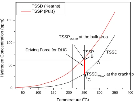
Fig. 2. Terminal solid solubility hysteresis of hydrogen during a thermal cycle to which the
Zr-2.5Nb tubes are subjected during DHC tests. The driving force for DHC is the
supersaturated hydrogen concentration
∆
C corresponding to the distance BC in Zr-2.5Nb with
2.2. New DHC model
It should be noted that under a stress gradient, the transfer of hydrogen occurs only under thermal cycling, not under thermal annealing at a fixed temperature without any prior cooling (Kammenzind, 2000). This experimental fact hints some effect of cooling on the hydrogen transfer, which is in conflict with Kammenzind’s argument (2000).
Zirconium alloys are well known to have hysteresis of the TSS of hydrogen on heat-up and cool-down due to a volume difference of around 17% between the δ-zirconium hydrides and the zirconium matrix as shown in Fig. 2 (Puls, 1984). Though the zirconium lattice is contracted on cooling with a driving force to precipitate dissolved hydrogen into hydrides, the increased lattice strain energy resulting from the precipitating hydrides with a larger volume by around 17%, thus, suppresses precipitation of the hydrides. This leads the zirconium matrix to have a higher dissolved hydrogen concentration upon cooling as opposed to the equilibrium hydrogen concentration upon heating. That is why the TSSP becomes larger than the TSSD as shown in Fig. 2.
When the Zr-2.5Nb compact tension (CT) specimen with a hydrogen concentration in excess of 60 ppm H is heated up to a peak temperature of 310 oC in a thermal cycle, it dissolves hydrogen whose concentration corresponds to the A point (as shown in Fig. 2) following the TSSD line. On cool-down to the test temperatures or 250 oC from the peak temperature, the Zr-2.5Nb specimen keeps all the hydrogen dissolved without precipitating any hydrides out of the zirconium matrix hydrostatically compressed by cooling. This corresponds to a case where the TSSD at the peak temperature is less than the TSSP at the test temperature. It leads the specimen to have the supersaturation of the dissolved hydrogen because the equilibrium hydrogen concentration that the Zr-2.5Nb specimen can dissolve is equal to the C point of Fig. 2, following the TSSD line. The amount of supersaturation of hydrogen, thus, corresponds to the distance BC as shown in Fig. 2. In general, the maximum supersaturated hydrogen concentration that the zirconium matrix can have in the thermal cycle will be TSSP-TSSD at any temperatures when the specimen is charged to a hydrogen concentration that is sufficient to exceed the TSSP at test temperatures. When a tensile stress is applied to Zr-2.5Nb CT specimens with a crack maintaining the supersaturated concentration of the dissolved hydrogen, the work energy given by the applied tensile stress will compensate for part of the increased strain energy by the precipitating hydrides with a larger volume. Hence, this will facilitates precipitation of the hydrides only at the crack tip. This causes the supersaturated hydrogen concentration at the crack tip to be reduced ultimately to the equilibrium hydrogen concentration or TSSD. In other words, the tensile stress applied at the crack tip will act to trigger nucleation of the hydrides only at the crack tip, thus decreasing the supersaturated hydrogen concentration to the TSSD at the test temperature or the C point as shown in Fig. 2. In contrast, the bulk region, which is subjected to small tensile stress, still maintains the supersaturation of hydrogen. This consequently leads to the development of a difference in the hydrogen concentration or ∆C between the crack tip and the bulk region corresponding to the distance BC, as shown in Fig. 3. Therefore, there arises a driving force for hydrogen to move from the bulk region to the crack tip. This difference in the hydrogen concentration or the amount of supersaturation of hydrogen (∆C) is a driving force for the DHC. It should be noted that the maximum hydrogen concentration difference, ∆Cmax is the TSSP-TSSD at any test temperatures as shown in Fig. 2. On the contrary, if the charged
hydrogen concentration is less than ∆Cmax (=TSSP-TSSD) at the test temperature, then the DHCV will be greatly
affected with the hydrogen concentration. In essence, the driving force for the DHC is a hysteresis of the TSS on heating and cooling..
A model experiment was conducted to demonstrate the feasibility of the new DHC model proposed where the effect of plastic deformation on precipitation of reoriented hydrides and their effect on DHC susceptibility were investigated during a thermal cycle treatment of a Zr-2.5Nb tube. Furthermore, the effect of the supersaturated hydrogen concentration on the DHCV was also investigated using the Zr-2.5Nb compact tension specimens with the hydrogen concentration changing from 12 to 100 ppm.
3. EXPERIMENTAL PROCEDURES
The applied stress intensity factor was 12 MPa√m at the beginning stage of the pre-fatigue crack and decreased to 10 MPa√m after the fatigue crack grew to 1.7 mm.
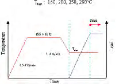
For DHC tests, CT and CB specimens were subjected to dead-weight loading in a creep machine and in a cantilever beam tester, respectively, while the initiation and growth of the crack were monitored by a direct current potential drop method. Fig. 3 shows a typical thermal cycle to which all the specimens were subjected during DHC tests. The specimens were heated to a peak temperature by 0.5-1 oC/min., held at the peak temperature for 1 h and cooled down to the test temperature followed by dead-weight loading 30 minutes after reaching the test temperature. The peak temperature was set at 10 oC higher than the TSSD temperature corresponding to the charged hydrogen concentration so as to completely dissolve the charged hydrogen into solution at the peak temperature. The crack length was determined on the fractured surface by dividing the area of the DHC crack calculated by an image analyzer by the width.
Fig. 3. A typical thermal cycle to which all the specimens were subjected for the DHC tests
along with the loading schedule.
4. RESUTLS
4.1 Applied Stress Effect on DHC Initiation in a Thermal Cycle
The feasibility of the new DHC model proposed here can be proven if the applied tensile stress facilitates precipitation of the hydrides from zirconium with supersaturated hydrogen, thereby causing a hydrogen concentration gradient. To this end, a model experiment was conducted where the same tensile stress corresponding to 18.4 MPa√m was applied to the CB specimens at different times in a thermal cycle as shown in Fig. 4: first, at the beginning of the cycle or at room temperature (A point); second, at the end of a 50 hour-hold at the peak temperature (B point) and third, at the beginning of the test temperature (C point). It should be noted that the stress intensity factor of 18.4 MPa√m (termed K) is calculated based on the assumption that a notch with 0.05 mm radius in the CB acts as a sharp crack (Yun, 2003). With the K applied at the points A or B, the reoriented hydrides precipitated over almost the whole cross-section and at a small area near the crack tip, respectively, as shown in Figs. 5a and 5b. With the same K applied at the test temperature of 250 oC, however, slight precipitation of reoriented hydrides was observed, as shown in Fig. 5c..
Fig. 4. Thermal cycle treatment to which the Zr-2.5Nb cantilever beam specimens were
subjected during DHC tests where the loading time with the stress intensity factor of 18.4
MPa
√
m changed: at RT (A point), at the end of the hold at the peak temperature (B point) and
at the test temperature (C point).
In essence, the role of an applied tensile stress is to facilitate precipitation of the hydrides in the zirconium matrix with the supersaturated hydrogen by cooling, not to move dissolved hydrogen up against a tensile stress gradient as suggested in the existing DHC models. The hydrides can precipitate either during cooling (Fig. 5a) or at the test temperature lowered by 50 oC from the peak temperature (Fig. 5c). However, precipitation of the hydrides during cooling decreases the concentration of supersaturated hydrogen in the zirconium matrix finally to the equilibrium hydrogen concentration. Thus, with the reoriented hydrides precipitated all over the cross section during cooling (Fig. 5a), then the whole area of the specimen does not maintain the supersaturated hydrogen but has the hydrogen concentration reduced to the equilibrium hydrogen concentration in accordance with the TSSD. Even after the specimen is cooled to the test temperature and is held there under an applied tensile stress, then, no hydrides can precipitate even at the crack tip due to no supersaturation of hydrogen, leading to no DHC as shown in Fig. 5a. In contrast, when the hydrides precipitate only at the test temperature, not on cooling as shown in Fig. 5c, the specimen becomes saturated with dissolved hydrogen in the zirconium matrix that is compressed hydrostatically by cooling. Since the applied tensile stress facilitates precipitation of the reoriented hydrides preferentially at the crack tip, the crack tip has the reduced hydrogen concentration but the bulk region that still maintains the supersaturated hydrogen in solution. Therefore, a gradient of the hydrogen concentration or a driving force for the transfer of hydrogen is developed between the crack tip and the bulk region, leading to the initiation of DHC crack as shown in Fig. 12c.
(b) (a)
(c)
DHC crack DHC crack
Fig. 5. Reorientation of hydrides in the Zr-2.5Nb tube with time of application of the stress
intensity factor of 18.4
√
m MPa on the CB specimens during the thermal cycle treatment shown
in Fig. 4: (a) at the beginning of the thermal cycle, (b) at the end of the hold at the peak
temperature of 380
oC and (c) at the test temperature of 250
oC.
than that in the region under the lowest tensile stress. This results in a gradient of the amount of the precipitated hydrides between the stressed region and the unstressed region though the dissolved hydrogen concentration is kept constant between the unstressed and stressed regions. This leads the stressed region to have the increased hydrogen concentration compared to that of the unstressed region as observed by Kammenzind (2000). Consequently, the transfer of hydrogen only under thermal cycling as reported by Kammenzind (2000) occurs due to the enhanced precipitation of the hydrides by a tensile stress in the stressed region at the cooling stage of the thermal cycling.
4.2 Dependence of Hydrogen Concentration on DHCV of Zr-2.5Nb
According to the new DHC model, since the driving force is the ∆C or the supersaturated hydrogen concentration over the TSSD at a test temperature, as shown in Fig. 2, DHCV should have a hydrogen-concentration dependency at the charged hydrogen concentration equal to and less than the TSSP at the test temperature and will become independent of the hydrogen concentration in excess of the TSSP. To ascertain the feasibility of our new DHC model, DHCV of the Zr-2.5Nb tube was determined at 182 oC with the charged hydrogen concentration changing from 10 ppm to 50 ppm. Fig. 6 shows a DHCV dependence for the Zr-2.5Nb tube on the supersaturated hydrogen concentration. As expected, the DHCV increased with the concentration of supersaturated hydrogen and leveled off to a constant. From the results shown in Fig. 6, we conclude that ∆C governs the DHCV as suggested by the new DHC model.
5. DISCUSSIONS
5.1. Supersaturation of Hydrogen
Since DHC is associated with hydrides, it will be governed by the factors affecting precipitation of the hydrides such as the concentration of supersaturated hydrogen or ∆C, cooling and tensile stress. The best way to make the supersaturation of dissolved hydrogen in zirconium is cooling: cooling from the peak temperature to the test temperature, as shown in Fig. 1, is required to create the supersaturated hydrogen for the DHC. Experimental evidence to this was provided in Fig. 1 where the TSSP temperature generally corresponded to the DHC initiation temperature at the hydrogen concentration in excess of 20 ppm or at the TSSP temperature in excess of 180 oC. This fact explains why the DHC cannot occur in zirconium alloys subjected to no thermal cycle at test temperatures higher than 200 oC (Ambler, 1978, Shek, 1988). The fact that the DHC initiation temperatures generally correspond to the TSSP temperatures at the hydrogen concentration in excess of 20 ppm suggests that an applied tensile stress does not affect the starting temperature where the hydrides can precipitate but causes their enhanced precipitation at the stressed region. In contrast, at as low a hydrogen concentration as 7 ppm, the DHC occurred with little cooling as shown in Fig. 1, indicating that the stress induced transformation of γ-hydrides to
δ-hydrides likely causes the transfer of hydrogen towards the crack tip from the bulk region (Nath, 1973, Root, 1996).
0 10 20 30 40
1E-9 1E-8 1E-7
DH
C Velocity (m/s)
Supersaturated H Content, ∆C(ppm)
Fig. 6. DHCV at 182
oC of the Zr-2.5Nb tube as a function of the supersaturated hydrogen
K>K
IHK<K
IH(a) (b)
K> K
(c)IH
σ
fσ
fσ
fCrack Tip
Distance from the crack tip Reoriented Hydride Reoriented Hydride
No Hydride fracture
Little
∆
C/
∆
x
Higher
σ
ys, Smaller SS,
Higher
∆
C/
∆
x
Higher DHCV
Lower
σ
ys, Larger SS,
Lower
∆
C/
∆
x
Lower DHCV
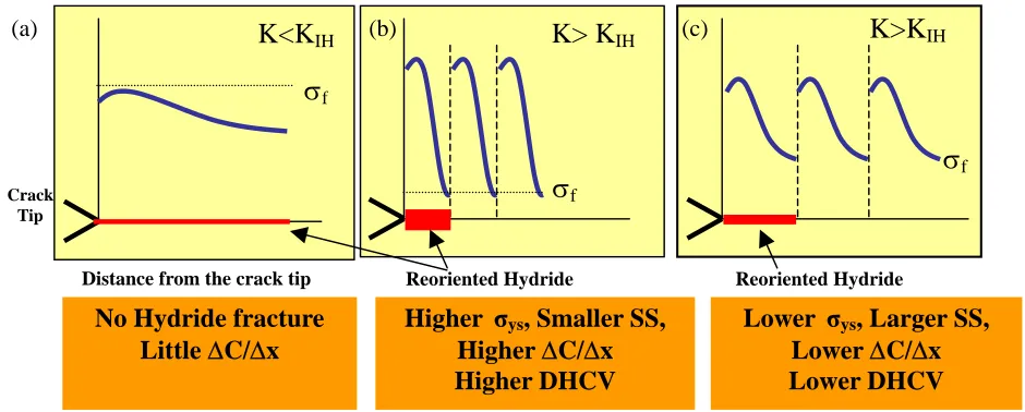
Fig. 7. Dependence of the plastic zone size at the crack tip on fracturing of hydrides and yield
strength: (a) wide plastic zone size without fracturing of hydrides, (b) smaller plastic zone due
to a higher yield strength and (c) comparatively larger plastic zone due to a lower yield
strength.
5.2. Constant DHCV independent of Stress Intensity Factors in Excess of KIH
With the applied stress intensity factor or K in excess of the threshold stress intensity factor, KIH, the
maximum concentration of supersaturated hydrogen or ∆Cmax that the Zr-2.5Nb specimens can have between the
crack tip and the bulk region is the TSSP-TSSD at the test temperature as shown in Fig. 2:
∆Cmax=TSSP-TSSD (1)
at a constant temperature and hydrogen concentration. In other words, the ∆C or the driving force for the DHC becomes independent of the K as long as it exceeds the KIH at the conditions of constant temperature and hydrogen
concentration. However, since the DHCV is governed by a hydrogen concentration gradient, a discussion has to be made not only about the driving force or ∆C, but also the plastic zone, or ∆s where the ∆C is developed. Necessary condition for a DHC crack to grow continuously is fracturing of the hydrides precipitated at the crack tip. The gradient of the hydrogen concentration formed at the crack tip under the applied K would decrease gradually with time unless the hydrides fracture as shown in Fig. 7a. With the applied K in excess of the KIH as
shown in Figs. 7b and 7c, the hydrides precipitate ahead of the crack tip, grow to the critical length corresponding to the KIH and then fracture. As soon as the crack grows through fracturing of hydrides, the hydrogen
concentration gradient will go away. Then, the grown crack waits until the start of the next cycle where the hydrides precipitate, grow and fracture over the newly formed plastic zone ahead of the crack tip, whose size is the same as the former plastic zone size. The plastic zone size is, therefore, determined by the yield strength of the zirconium alloys and the KIH, not by the applied K because the hydrides fracture whenever the applied K reaches
the KIH (Choi, 2004): 2
=
∆
y IH
K
k
s
σ
, (2)where ∆s is the plastic zone size, k is a constant, KIH is the threshold stress intensity factor and σY is the yield
strength. As shown in Eqs. 1 and 2, the ∆s and ∆C, governing the hydrogen concentration gradient at the crack tip, becomes independent of the applied K, leading to the constant DHCV independent of the applied K. In essence, the constant DHCV independent of the applied K is attributed to the constant driving force or ∆C independent of the applied K and the constant plastic zone size due to the discontinuous growth of the crack at the constant KIH.
I
Z
P
p
striation spacing on the DHC fracture surfaces has a yield strength dependence and full independence of the applied K (Kim, 2004, Choi, 2004).
6. CONCLUSIONS
For the first time, we propose a new DHC model where a driving force for DHC of zirconium alloys is the supersaturated hydrogen concentration or ∆C resulting from hysteresis of the terminal solid solubility of hydrogen in zirconium upon heating and cooling. Experimental evidence to the feasibility of the new DHC model was provided through the model experiments: the applied stress promoted precipitation of the reoriented hydrides in the plastic zone, no DHC occurred in the absence of the supersaturation of hydrogen resulting from the reoriented hydrides precipitated all over the cross-section on cooling, and the DHCV of the Zr-2.5Nb tube increased with the
∆C and leveled off to a constant at the ∆C in excess of TSSP-TSSD at the test temperature. The new DHC model proposed here comprehends the constant DHCV independent of the K accounting for the facts that the ∆C becomes independent of the K and the plastic zone size ∆s is governed by the yield strength and the threshold stress intensity factor over which the hydrides precipitated at the crack tip fracture, initiating the DHC.
REFERENCES
Ambler, J.F.R., Coleman, C.E., (1978), Hydrogen in Metals, Pergamon Press, Oxford, 3C10. Cahn, R.W., (1965), “Physical Metallurgy”, 3rd ed. North-Holland, New York, 535.
Carpenter, G.J.C., (1973), J. Nucl. Mater., Vol.48, pp.264-266.
.Choi, S.J, Ahn S.B, Park, S.S, Kim, Y.S., (2004), KSME, Vol.28A, pp.1109-1115.
Coleman, C.E., Ambler, J.F.R., (1977), “Zirconium in the nuclear industry”, ASTM STP 633, 589. Dutton, R., Nuttal, K., Paton, N.E., (1977), Met. Trans., Vol.8A, pp.1553-1562.
Eadie, R.L., Coleman, C.E., (1989), Scripta Metall., Vol.23, pp.1865-1870. Eadie, R.L., Metzger, D.R., Leger, M., (1993), Scripta Metall., Vol.29, pp.335-340. Gangloff, R.P., Wei, R.P., (1977), Met. Trans., Vol.8A, pp.1043-1053.
Hirth, J.P., (1984), “Hydrogen Embrittlement and Stress Corrosion Cracking”, ASM, Ohio, 29.
Kammenzind, B.F., Berquiest, B.M., Bajaj, R., Kreyns, P.H, Franklin, D.G., (2000), “Zirconium in the Nuclear ndustry”, ASTM STP 1354, 196.
Kearns, J.J., (1967), J. Nucl. Mater., Vol.22, pp.292-303.
Kerns, G..E., Staehle, R.W., (1972), Scripta Met., Vol.6, pp. 1189-1194. Kim, Y.S., (1999), KAERI/TR-1329/99.
Kim, Y.S., Perlovich, Y., Isaenkova M., Kim S.S., Cheong, Y.M., (2001), J. Nucl. Mater., Vol. 297, pp. 292-302. Kim, YS, Kim SS, Ahn, SB, Cheong, Y.M., (2004), “Governing Factors for Delayed Hydride Cracking in
r-2.5Nb tubes” presented at the 14th ASTM Symposium on Zirconium in the Nuclear Industry, Stockholm. Li, J.C.M., Oriani, R.A., Darken L.S., (1966), Z. Phys. Chem. Nev. Folge., Vol. 49, p. 271.
Magdowki, R.M., Speidel, M.O., (1988), Met. Trans, Vol. 19A, pp.1583-1596.
MacEwen, S.R., Coleman, C.E., Ells, C.E., Faber Jr., J.,(1985), Acta Met., Vol.33, pp 753-757 Nath, B, Lorimer, G.W., Ridley, N., (1973/74), J. Nucl. Mater., Vol. 49, pp. 262-280.
Nuttal, K., Rogowski, A.J., J. Nucl. Mater., Vol.80, pp.279-290.
Pan, Z.L., Ritchie, I.G., Puls, M.P.,, (1996), J. Nucl. Mater., Vol.228, pp.227-237. Puls, M.P., (1981), Acta Met., Vol.29, pp.1961-1968.
Puls, M.P., Simpson, L.A., Dutton R., (1982), “Fracture Problems and Solutions in the Energy Industry”, ergamon Press, Oxford, 13.
Puls, M. P., (1984), Acta Metal., Vol.32, pp.1259-1269.
Root, J.H., Fong, R.W.L, (1996), J. Nucl. Mater., Vol.232, pp.75-85.
Staehle. R.W., (1996), Proc. 2nd Seminar on Nuclear Materials and Related Technology, 6-1. Shi, S.Q., Puls, M.P., (1994), J. Nucl. Mater., Vol.218, pp.30-36.
Shi. S.Q., G.K. Shek, Puls, M.P., (1995), J. Nucl. Mater., Vol. 218, pp.189-201.
Shek, G. K., Graham, D.B., “Zirconium in the Nuclear Industry”, ASTM STP 1023, 89. Slattery, G.F., (1967), J. Nucl. Mater., Vol.95, pp.43-47.
Yun, Y. B., Kim. Y.S., Im, K.S., Cheong, Y.M., Kim, Y.S., (2003), Journal of the Korean Nuclear Society, Vol.35, p.529-536.