585-210-940
Comcode 108502352
Issue 1
Your Responsibility for Your System’s Security
Toll fraud is the unauthorized use of your telecommunications system by an unauthorized party, for example, persons other than your com-pany’s employees, agents, subcontractors, or persons working on your company’s behalf. Note that there may be a risk of toll fraud associ-ated with your telecommunications system and, if toll fraud occurs, it can result in substantial additional charges for your telecommunica-tions services.
You and your system manager are responsible for the security of your system, such as programming and configuring your equipment to pre-vent unauthorized use. The system manager is also responsible for reading all installation, instruction, and system administration docu-ments provided with this product in order to fully understand the fea-tures that can introduce risk of toll fraud and the steps that can be taken to reduce that risk. Lucent Technologies does not warrant that this product is immune from or will prevent unauthorized use of com-mon-carrier telecommunication services or facilities accessed through or connected to it. Lucent Technologies will not be responsible for any charges that result from such unauthorized use.
Lucent Technologies Fraud Intervention
If you suspect that you are being victimized by toll fraud and you need technical support or assistance, call Technical Service Center Toll Fraud Intervention Hotline at 1-800-643-2353.
Trademarks
CentreVu is a registered trademark of Lucent Technologies.
AnswerBook, Enterprise, Solaris, SunLink, and Solstice DiskSuite are
trademarks of Sun Microsystems, Inc.
Sun and Sun Microsystems are registered trademarks of Sun
Microsys-tems, Inc.
INFORMIX is a registered trademark of Informix Software, Inc. Ordering Information
Call: Lucent Technologies Publications Center Voice: 1-800-457-1235
International Voice: 317-322-6416 Fax: 1-800-457-1764
International Fax: 317-322-6699
Write: Lucent Technologies BCS Publications Center 2855 N. Franklin Road
Indianapolis, IN 46219 Order: Document No. 585-210-940
Comcode 108502352 Issue 1, December 1999
You can be placed on a Standing Order list for this and other docu-ments you may need. Standing Order will enable you to automatically receive updated versions of individual documents or document sets, billed to account information that you provide. For more information on Standing Orders, or to be put on a list to receive future issues of this document, contact the Lucent Technologies Publications Center.
AT&T titles. Heritage Statement
Lucent Technologies—formed as a result of AT&T’s planned restruc-turing—designs, builds, and delivers a wide range of public and pri-vate networks, communication systems and software, consumer and business telephone systems, and microelectronics components. The world-renowned Bell Laboratories is the research and development arm for the company.
Comments
To comment on this document, return the comment card at the front of the document.
Acknowledgment
Table of Contents
Chapter 1:
Introduction to Disk MirroringDisk mirroring defined . . . 1
Metadevices. . . 1
Concatenated metadevices . . . 2
State databases . . . 3
Mirrors. . . 3
How CMS implements disk mirroring . . . 5
Mirror layouts . . . 7
Mirror layout on a Sun Enterprise 3000 computer . . . 7
Mirror layout on a Sun Enterprise 3500 computer . . . 8
Required hardware . . . 8
Required software . . . 9
Additional references . . . 9
Chapter 2:
Installing Mirrored Systems How to upgrade an Enterprise platform to disk mirroring . . . 11Disk drive slots . . . 11
Increasing system capacity . . . 12
Step 1: Identify mirror devices. . . 12
Step 2: Install the mirror disks on an Enterprise 3500 system . . . 14
Step 3: Install the mirror disks on an Enterprise 3000 system . . . 16
Step 4: Partition the mirror disks . . . 16
Step 5: Create the state database replicas . . . 18
Step 6: Create the md.tab table entries . . . 18
Step 7: Set up the mirrors for the root file system . . . 20
Step 8: Set up the mirrors for the swap space . . . 22
Step 9: Set up the /cms mirror . . . 24
Step 10: Verify disk space . . . 25
Step 11: Create an alternate boot device . . . 26
Factory installation procedures for disk mirroring . . . 28
Step 1: Install the hardware . . . 28
Step 2: Install the operating system. . . 28
Step 3: Install the application software . . . 29
Step 4: Check the disk.type file . . . 30
Step 5: Set up the disk subsystem for Solstice DiskSuite . . . 30
Step 6: Run the setup scripts . . . 32
Step 7: Verify disk space . . . 33
Step 8: Install the CMS software. . . 35
Chapter 3:
Maintaining Mirrored SystemsUsing the alternate boot device . . . . 39
Maintaining the chkDisks crontab . . . . 40
Activating chkDisks . . . . 40
Verifying chkDisks. . . . 40
Changing the scheduled run time . . . . 40
Canceling chkDisks . . . . 40
Doing a CMSADM backup on a mirrored system . . . . 41
Step 1: Print the vfstab file . . . . 41
Step 2: Run the backup . . . . 41
Step 3: Label and store the tapes . . . . 42
Restoring from a CMSADM Backup . . . . 43
Repairing or rebuilding the /cms file system . . . . 45
Repairing /cms . . . . 45
Rebuilding /cms . . . . 46
Restoring a mirrored system from a CMSADM backup. . . . 49
Step 1: Power off the system . . . . 49
Step 2: Install the new drives . . . . 49
Step 3: Boot the system from the compact disk . . . . 50
Step 4: Identify the system . . . . 51
Step 5: Set the Name Service options . . . . 52
Step 6: Set the date and time . . . . 53
Step 7: Select the operating system files to be installed . . . . 54
Step 8: Select the hard disks . . . . 55
Step 9: Set up the disk partitions. . . . 55
Step 10: Install the operating system . . . . 57
Step 11: Complete the OS installation . . . . 58
Step 12: Alter the tape configuration file (Enterprise 3500 only) . . . . 58
Step 13: Restore the backup . . . . 59
Step 14: Reestablish the disk mirrors . . . . 59
Restoring specific files from a CMSADM backup . . . . 62
Adding new disks to a standard mirrored system . . . . 63
Adding new disks to a nonstandard mirrored system . . . . 66
Replacing a faulty disk . . . . 69
Step 1: Identify the faulty disk . . . . 69
Step 2: Identify the submirrors . . . . 70
Step 3: Detach the submirrors . . . . 71
Step 4: Remove state database replicas (boot disks only) . . . . 72
Step 5: Replace the faulty disk drive . . . . 72
Step 6: Recreate the state database replicas . . . . 73
Step 7: Reattach the submirrors . . . . 74
Step 8: Reboot the system (boot disks only) . . . . 74
State Database Replicas . . . . 75
Setting up replicas. . . . 75
Partitioning disks with the format command . . . . 76
How to tell whether your mirrored system is standard . . . . 78
Examples of valid system files . . . . 79
Valid vfstab files . . . . 79
Valid md.tab files . . . . 80
Chapter 4:
Troubleshooting Solstice DiskSuite problems . . . . 81The root filesystem runs out of space during a system install . . . . 81
Excessively long resync . . . . 81
The system fails to recognize all disk drives . . . . 82
Fixing “needs maintenance” messages . . . . 84
Boot problems . . . . 85
Trying to boot from the wrong device . . . . 85
Primary boot device is not available . . . . 85
Excessive reboot time. . . . 86
Log files . . . . 87
Error messages . . . . 88
1
Introduction to Disk Mirroring
1This chapter introduces you to “disk mirroring,” an optional feature of CentreVu Call Management System (CMS) that provides you with a completely redundant set of data, helping to ensure data security. To use disk mirroring, you must have a Sun* Enterprise* 3000 or Sun Enterprise 3500 platform running CMS r3v8.
Disk mirroring defined
1“Mirrors” are a feature of the Solstice DiskSuite* software package. They allow you to build a hard disk system containing two—or even three— complete sets of data. Having such data redundancy greatly reduces the risk of data loss should a hard disk drive fail or your system crash. While mirrors greatly reduce the risk of losing data, however, they are not meant to be a substitute for regular backups. Mirrored systems must be backed up just as often as unmirrored systems.
Metadevices
1 The Solstice DiskSuite software package allows multiple disk partitions tobe logically combined to create a single large partition. Using the Solstice DiskSuite package allows CMS databases to span multiple disks, and so grow quite large.
Solstice DiskSuite uses virtual disks to manage physical disks and their associated data. In Solstice DiskSuite, a virtual disk is called a
metadevice. To a software application, a metadevice is identical to a physical disk drive. Solstice DiskSuite handles all I/O requests directed at a metadevice, converting them into I/O requests for the underlying disks.
Solstice DiskSuite metadevices are built from slices (disk partitions). A system controlled by Solstice DiskSuite may contain any number of metadevices, each of which may comprise any combination of disk partitions.
Once a metadevice has been set up, the underlying disk partitions can be accessed only through the metadevice.
The illustration below shows a simple, two-slice metadevice.
Concatenated
metadevices
1A metadevice can be configured as any one of three basic types: striped, concatenated, or concatenated stripes. The type used by CMS systems is the concatenated metadevice. In a concatenated metadevice, data blocks, or chunks, are written sequentially across the slices, beginning with the first disk.
Consider, for example, a concatenated metadevice with three slices (see the illustration below.) In that scenario, disk A can be envisioned as containing logical chunks 1 through 4, disk B as containing logical chunks 5 through 8, and disk C as containing chunks 9 through 12.
c0t0d0s2
c1t0d0s2 c0t0d0s2
Physical Disks A & B Metadevice d0
c1t0d0s2
Chunk 3 Chunk 4 Chunk 2 Chunk 1
Chunk 7 Chunk 8 Chunk 6 Chunk 5
Chunk 11 Chunk 12 Chunk 10 Chunk 9
Solstice DiskSuite . . . Chunk 2 Chunk 1
Chunk 12
. . . . . .
Physical Disk A
Physical Disk B
Physical Disk C
The total capacity of this concatenated metadevice is the combined capacities of the three drives. If each drive is 4 gigabytes, for example, the metadevice has an overall capacity of 12 gigabytes.
State databases
1 The Solstice DiskSuite software tracks which disk partitions belong to which metadevices with a state database. A state database stores information on disk about the state of your Solstice DiskSuite configuration.The state database consists of multiple copies of the basic database. The copies, referred to as state database replicas, ensure that the data in the database is always valid. Having multiple copies protects against data loss from single points-of-failure. The state database tracks the location and status of all state database replicas. Solstice DiskSuite cannot operate until you have created the state database and its replicas: the software must have an operating state database.
Mirrors
1 A mirror is a metadevice that can copy data from one metadevice toanother. The metadevices containing the data are called submirrors. The process of copying the data between submirrors is called mirroring.
Mirroring provides redundant copies of data. To a software application, a mirror looks just like a physical disk. The mirror accepts I/O requests and converts them into I/O requests for the submirrors. The submirrors in turn—being metadevices themselves—convert I/O requests from the mirror into I/O requests for the underlying physical disks.
Chunk 3 Chunk 4 Chunk 2 Chunk 1
Chunk 3 Chunk 4 Chunk 2 Chunk 1
Solstice DiskSuite
Metadevice d19
Metadevice d20
Metadevice d21
How CMS implements disk mirroring
1A nonmirrored, CMS system with Solstice DiskSuite uses it to create a single metadevice, named d19, containing all the disk partitions used to store CMS data. For example:
To implement disk mirroring, a metadevice d20 is created as a duplicate of d19, and the two metadevices are configured as submirrors of d21, as shown in the following example:
d19 /cms
. . .
c0t0d0s3 c0t1d0s1 (disk n)
d19 /cms
. . .
c0t0d0s3 c0t2d0s1 (disk n)
d20 d21
c0t1d0s3 c0t3d0s1 (disk n)
In a CMS computer system with /cms mirrored, root is also mirrored. The root mirror is d13; its submirrors are d11 and d12. For example:
If your computer system is running CMS r3v8, your swap partition is also mirrored. The swap mirror is d17; its submirrors are d15 and d16. For example:
d11 / (root)
c0t0d0s0
d12 d13
c0t1d0s0
d15 swap
c0t0d0s4
d16 d17
Mirror layouts
1 Mirror layouts on a factory-installed mirrored system differ depending upon the platform. When a system is upgraded to mirroring in the field, mirror layouts are essentially unpredictable, and depend on how many disk drives are already installed, and what their target numbers are.Mirror layout on a Sun
Enterprise 3000
computer
1On a Sun Enterprise 3000 platform with factory-installed mirroring, the mirror layout is the simple odd/even arrangement shown in the table below. A system upgraded to mirroring in the field probably has a different mirror layout.
mirror d13 (/ (root) filesystem)
mirror d21 (/cms filesystem) mirror d17 (swap partition) (CMS r3v8) No. Disks submirror d11 submirror d12 submirror d19 submirror d20 submirror d15 submirror d16
2 c0t0d0s0 c0t1d0s0 c0t0d0s3 c0t1d0s3 c0t0d0s4 c0t1d0s4
4
c0t0d0s0 c0t1d0s0 c0t0d0s3
c0t2d0s1
c0t1d0s3
c0t3d0s1 c0t0d0s4 c0t1d0s4
Mirror layout on a Sun
Enterprise 3500
computer
1On a Sun Enterprise 3500 platform, the mirror layout must always be based upon the bays in which the disks are installed. Submirrors 11, 15, and 19 are the disks in the lower bay (targets 0 through 3 on controller 0); submirrors 12,16, and 20 are the disks in the upper bay (targets 4 through 7 on controller 1). The table below shows the mirror layout.
Required hardware
1 In order for your CMS system to be mirrored, it must have the followinghardware installed in addition to the hardware already installed:
● For a Sun Enterprise 3500 system, two GigaByte Interface
Converter (GBIC) modules. One will be installed into the UA slot on the FC-AL Interface board, and the other will be installed into GBIC Port 1 on the Sbus I/O board (see the illustration on page 15).
● For a Sun Enterprise 3500 system, a fiber cable to connect the UA
port GBIC to GBIC Port 1 on the I/O board.
● Twice the number of disk drives needed for an unmirrored system.
All the disks must be the same size. mirror d13
/ (root) filesystem
mirror d21 /cms filesystem mirror d17 swap partition (CMS r3v8) No. Disks submirror d11 submirror d12 submirror d19 submirror d20 submirror d15 submirror d16
2 c0t0d0s0 c1t4d0s0 c0t0d0s3 c1t4d0s3 c0t0d0s4 c1t4d0s4
4 c0t0d0s0 c1t4d0s0 c0t0d0s3
c0t1d0s1
c1t4d0s3
c1t5d0s1 c0t0d0s4 c1t4d0s4
6 c0t0d0s0 c1t4d0s0
c0t0d0s3 c0t1d0s1 c0t2d0s1 c1t4d0s3 c1t5d0s1 c1t6d0s1 c0t0d0s4 c1t4d0s4
8 c0t0d0s0 c1t4d0s0
Required software
1 In order for your CMS system to be mirrored, it must be running the following software:For a list of other software required for your system, see the Lucent Technologies Software Installation manual for your version of CMS.
Additional
references
1Sun Microsystems* documentation related to Solstice DiskSuite and disk maintenance and configuration includes:
Solstice DiskSuite 4.2 Administration Guide Solstice DiskSuite Tool 4.2 User‘ s Guide
CMS R3V8 Solaris 7 dated 3/99
Solstice DiskSuite 4.2
any CMS r3v8 load
2
Installing Mirrored Systems
2This chapter contains procedures for upgrading existing computer systems to use disk mirroring and for installing a mirrored system under factory conditions.
How to upgrade an Enterprise platform to disk mirroring
2This section tells how to upgrade CentreVu Call Management System (CMS) on a Sun Enterprise 3000 or 3500 computer from a nonmirrored system to a mirrored system.
Disk drive slots
2 Before you begin, you must understand the drive slot arrangement inyour system.
In an Enterprise 3000 computer, there are 10 slots, allowing up to five disks for each mirror. Each slot is labeled with a number 0 through 3 or 10 through 15; there are no slots numbered 4 through 9. All the drive slots are on controller 0.
In an Enterprise 3500 computer, there are eight disk drive slots, four in each of two bays. The slots in the lower bay are labeled 0 through 3 and are on controller 0; the slots in the upper bay are numbered 4 through 7 and are on controller 1. In a mirrored system, slots 0 through 3 are reserved for the original disks, and slots 4 through 7 are reserved for the mirror disks.
The slot number is the drive’s target number, which becomes part of the device name. A drive in slot 1, for example, has the device name c0t1d0. The drive in slot 0 is always the primary boot disk.
In an Enterprise 3000 mirrored system, mirror disks are normally installed in target number order, beginning with the first empty slot. That makes it difficult to predict the mirror layout on an upgraded system. In an
Increasing system
capacity
2If you intend to increase your system capacity as well as mirror your system, first install the new disks needed to increase capacity. For instructions, see the documentation that came with the new drives or the appropriate Lucent Technologies installation documents. After the system capacity has been increased, and it has been verified that the system works correctly, you may then install disk mirroring. You must make certain the basic system works before you try to mirror the disks.
Step 1: Identify
mirror devices
21. Check the number of new disks to be installed as the mirror.
There should be as many new disks to be installed as there are old disks already on your system. That keeps the same system capacity and makes the two submirrors the same size.
2. Next you must identify the device names for your mirrored system and record them in the Device/Metadevice Names table on the next page.
If you have an Enterprise 3500 system, the device names have already been identified and recorded for you in the Enterprise 3500 table. Here’s how you identify the device names for an
Enterprise 3000 system:
a. Identify the secondary boot disk and record the device names.
Find the first empty slot in your system. Whatever slot you find will hold the secondary boot disk. Then record the following device names for that disk:
● Record the slice 0 device name as submirror 12.
● Record the slice 3 device name as disk 1 of submirror 20.
● If your system is running load r3v6aj.c or later of CMS—
you can find out by executing a pkginfo -x cms
command—record the slice 4 device as submirror 16.
Example: If the first empty drive slot in your system were slot 2, you would record the following values in the table:
Submirror d12
Device Name
. . .
Submirror d20 Device Names
boot disk (2): c0t2d0s0 CMS disk 1: c0t2d0s3
Submirror d16 Device (r3v6aj.c or later)
b. Record existing nonboot disks under submirror 19, and empty slots for new nonboot disks under submirror 20.
Example: Imagine a system that already has two disk drives in slots 0 and 1. In the previous step, you would have reserved slot 2 for the second boot disk. The remaining new disk is a nonboot disk and will be installed in slot 3. So you would record the following values in the table:
Submirror d19 Device Names
Submirror d20 Device Names
CMS disk 1: c0t0d0s3 CMS disk 1: c0t2d0s3
CMS disk 2: c0t1d0s1 CMS disk 2: c0t3d0s1
CMS disk 3: CMS disk 3:
CMS disk 4: CMS Disk 4:
CMS disk 5: CMS disk 5:
Device/Metadevice Names for an Enterprise 3000 system
Submirror d11 Device Name Submirror d12 Device Name Submirror d19 Device Names Submiror d20 Device Names
boot disk 1: c0t0d0s0 boot disk 2: s0 CMS disk 1: c0t0d0s3 CMS disk 1: s3
CMS disk 2: s1 CMS disk 2: s1
Submirror d15 Device Name (r3v6aj.c and later)
Submirror d16 Device Name (r3v6aj.c and later)
CMS disk 3: s1 CMS disk 3: s1
CMS disk 4: s1 CMS Disk 4: s1
swap, disk 1: c0t0d0s4 swap, disk 2 s4 CMS disk 5: s1 CMS disk 5: s1
Device/Metadevice Names for an Enterprise 3500 system
Submirror d11 Device Name Submirror d12 Device Name Submirror d19 Device Names Submiror d20 Device Names
boot disk 1: c0t0d0s0 boot disk 2: c1t4d0s0 CMS disk 1: c0t0d0s3 CMS disk 1: c1t4d0s3
Submirror d15 Device Name (r3v6aj.c and later)
Submirror d16 Device Name (r3v6aj.c and later)
CMS disk 2: c0t1d0s1 CMS disk 3: c1t5d0s1
CMS disk 3: c0t2d0s1 CMS Disk 4: c1t6d0s1
Step 2: Install the
mirror disks on an
Enterprise
3500
system
2Do this step only if you have an Enterprise 3500 system.
It is likely that your Enterprise 3500 system is currently using controller 1 (c1) for the internal CD-ROM drive. This step associates the CD-ROM drive with controller 2 (c 2) so controller 1 will be free for the new disk drives. In this step you also install some additional hardware for controlling the new disks, and install the new disks themselves. You should be logged in as root before beginning this step.
1. Enter the following command:
______________________________________________________
# ls -l /dev/dsk/c1t6d0s0
______________________________________________________
The system should respond with a line similar to the following: ______________________________________________________
lrwxrwxrwx 1 roor roor 50 Nov 16 08:58 /dev/dsk/c1t6d0s0 -> ../../devices/sbus@3,0 /SUNW,fas@3,8800000/sd@6,0:a
______________________________________________________
Notice that c1t6d0s0 is pointing to sd@6,0:a. That indicates that controller 1 is being used by the CD-ROM drive. Remove that association by entering the following commands:
______________________________________________________
# rm /dev/dsk/c1* # rm /dev/rdsk/c1* # touch /reconfigure
# /usr/sbin/shutdown -y -g0 -i0
______________________________________________________
2. Install new hardware components as follows:
● Install a GigaByte Interface Converter (GBIC) into slot UA on
the Interface board.
● Install another GBIC into port 1 on the SBus I/O board.
● Install a fiber cable between the two newly installed GBICs.
4. From the ok prompt, do a reconfigure boot by entering the following command:
______________________________________________________
ok boot -r
______________________________________________________
5. Log in as root.
6. Enter the following command:
______________________________________________________ # ls -l /dev/dsk/c2t6d0s0
______________________________________________________
The system should respond with a line similar to the following: ______________________________________________________
lrwxrwxrwx 1 roor roor 50 Nov 16 08:58 /dev/dsk/c2t6d0s0 -> ../../devices/sbus@3,0 /SUNW,fas@3,8800000/sd@6,0:a
______________________________________________________
Notice that c2t6d0s0 is pointing to sd@6,0:a, indicating that the CD-ROM drive is now on controller 2.
Step 3: Install the
mirror disks on an
Enterprise
3000
system
2Do this step only if you have an Enterprise 3000 system.
Install the new disk drives, which will form the mirror, into the empty slots reserved in step 1. Follow the procedure in the “Add a Disk Drive” subsection in the Lucent Technologies hardware installation or hardware maintenance manual for your version of CMS. DO NOT PARTITION THE DISKS JUST YET; that happens next.
Step 4: Partition the
mirror disks
2Partition the newly installed disks using the format command. If you have an Enterprise 3500, make certain that the new drives are named using “c1,” as c1t4d0 or c1t5d0.
The procedure is as follows:
1. Enter: # format
A menu of disks displays. You are asked to select one.
2. Enter the menu number of the new disk to be partitioned.
The format> prompt displays.
3. Enter: format> partition
4. Enter: partition> print
The partition table displays and the partition> prompt returns. Compare the display to the Partitioning table below to see whether you need to partition the disk. You probably will need to re-partition.
5. Enter the number of the partition to be reconfigured.
The system begins a series of prompts for partitioning information. Answer according to the CMS version and disk type you are partitioning (see the Partitioning table below).
Repeat this task for each partition on the disk.
6. Enter: partition> print
The partition table displays and the partition> prompt returns. Compare the display to the Partitioning table to make certain you have repartitioned the disk properly. If not, repeat step 5.
7. Enter: partition> label
The system responds Ready to label disk, continue?
Partitioning (Note: Never change the default size of the overlap slice!)
CMS R3V8 4.2-GB Disk
CMS R3V8 9.1-GB Disk SCSI (E3000) and FC-AL
(E 3500) Disk
Type Part Tag Flag
Size (cyl.)
Starting Cylinder
Size (cyl.)
Starting Cylinder Boot 0 boot disk 1: / or root
boot disk 2: unassigned
wm 1023 0 616 0
1 unassigned wm 7 1023 7 616
2 overlap or backup wm 3880 0 4924 0
3 unassigned wm 1879 1030 3716 623
4 swap wm 971 2109 585 4339
5-7 unassigned wm 0 0 0 0
Nonboot 0 unassigned wm 2 0 2 0
1 unassigned wm 3878 2 4922 2
2 overlap or backup wm 3880 0 4924 0
8. Enter: y
The partition> prompt returns.
9. Enter: partition> q
The format> prompt returns.
10. To select the next disk to be partitioned, enter: format> disk
and return to item 2.
If you have finished partitioning all the new disks, enter: format> q
and continue with the next step.
Step 5: Create the
state database
replicas
21. Alter your path by entering the following commands:
2. Create two state database replicas on slice 1 of boot disk 2:
(where <device> is the target number of boot disk 2)
3. Verify that the replicas were created by entering the following command:
The system lists the state database replicas currently on the system. The following sample output shows two replicas on c0t2:
Make sure the list includes the two replicas you just created.
Step 6: Create the
md.tab
table entries
21. Make copies of essential system files by entering these commands:
2. Edit /etc/opt/SUNWmd/md.tab and insert entries for the root and /cms metadevices. If your system is running CMS load r3v6aj.c or later, you must also create a section for the swap metadevice.
# export PATH=$PATH:/usr/opt/SUNWmd/sbin:/olds
# metadb -a -c3 -f /dev/rdsk/<device>
# metadb -i
flags first blk block count
a u 16 1034 /dev/dsk/c0t2d0s1
a pc luo 16 1034 /dev/dsk/c0t2d0s1
# cp /etc/opt/SUNWmd/md.tab /etc/opt/SUNWmd/md.tab.orig
# cp /etc/vfstab /etc/vfstab.orig
The root metadevice definitions go into the #metaroot section, which you must create for the occasion; d20 goes into the #/cms section, which already exists in the file. The swap metadevice definitions go into the #swap section which, like #metaroot, must be created for the occasion.
The lines you add must be in the following general format:
d<x> <y> 1 <device>
d<x> is the metadevice name.
<y> denotes the total number of disks named in the line.
1 <device> indicates one disk with the device name <device>. You should have recorded the device names on page 13.
The pattern 1 (space) <device> repeats until all disks in the
metadevice have been named. The d12 entry must specify one disk; the d20 entry must specify the same number of disks as the existing d19 entry. If your system has two disks in slots 0 and 1 and you are adding a two-disk mirror in slots 2 and 3, for example, you would add the md.tab lines shown in boldface in the following sample:
--- /etc/opt/SUNWmd/md.tab - EXAMPLE ONLY
---. . . #metaroot
d11 1 1 c0t0d0s0 d12 1 1 c0t2d0s0 d13 -m d11
#/cms
d19 2 1 /dev/rdsk/c0t0d0s3 1 /dev/rdsk/c0t1d0s1
d20 2 1 /dev/rdsk/c0t2d0s3 1 /dev/rdsk/c0t3d0s1
d21 -m d19
#metaswap (for load r3v6aj.c or later)
d15 1 1 c0t0d0s4
d16 1 1 c0t2d0s4
d17 -m d15
Step 7: Set up the
mirrors for the
root
file system
2Set up the mirrors for the root file system with the following steps:
1. Activate metadevice d11:
2. Activate metadevice d13:
3. Activate metadevice d12:
4. Attach d12 to d13:
5. Verify that root is set up and resynching:
Check the State: lines in the output list. They should read either
Okay or Resyncing. If they do, then everything is fine. If they indicate any other status, something has gone wrong with the setup: discontinue the upgrade and telephone the Lucent National
Customer Care Center (1.800.242.2121) or contact your Lucent representative or distributor.
# metainit -f d11
d11: Concat/stripe is set up #
# metainit -f d13
d13: Concat/stripe is set up #
# metainit -f d12
d12: Concat/stripe is set up #
# metattach d13 d12
d13: submirror d12 is attached #
# metastat d13 d13: Mirror
Submirror 0: d11 State: Okay Submirror 1: d12 State: Resyncing Pass: 1
Read option: roundrobin (default) Write option: parallel (default) Size: 2209680 blocks
6. Set up d13 as the root mirror:
7. Reboot the system and log in as the root user:
# metaroot d13 #
# /usr/sbin/shutdown -i6 -g0 -y
. . .
Step 8: Set up the
mirrors for the
swap space
2Set up the mirrors for the swap space with the following steps:
1. Activate metadevice d15:
2. Activate metadevice d17:
3. Activate metadevice d16:
4. Attach d16 to d17:
5. Verify that swap is set up and resynching:
Check the State: lines in the output list. They should read either
Okay or Resyncing. If they do, then everything is fine. If they indicate any other status, something has gone wrong with the setup: discontinue the upgrade and telephone the Lucent National
Customer Care Center (1.800.242.2121) or contact your Lucent representative or distributor.
# metainit -f d15
d15: Concat/stripe is set up #
# metainit d17
d17: Concat/stripe is set up #
# metainit d16
d16: Concat/stripe is set up #
# metattach d17 d16
d17: submirror d16 is attached #
# metastat d17 d17: Mirror
Submirror 0: d15 State: Okay Submirror 1: d16 State: Resyncing Pass: 1
Read option: roundrobin (default) Write option: parallel (default) Size: 2209680 blocks
6. Edit /etc/vfstab. The relevant portion of the file looks like this:
- /etc/vfstab
---. . .
/dev/dsk/c0t0d0s4 - swap - no
-/dev/dsk/c0t2d0s4 - swap - no
-
---Do the following steps to modify the file:
a. Copy the c0t0d0s4 entry and insert the copy on the succeeding line.
b. Comment out the original entry by inserting a pound sign at the beginning of the line.
c. Alter the copy by:
1. replacing c0t0d0s4 with d17 2. adding md/ after the dev/
d. Immediately after the line just added should be a line naming the secondary boot disk. Comment out that line by inserting a pound sign at the beginning of the line.
When you have finished a through d, the relevant lines of the file might look something like this:
- /etc/vfstab
---. . .
#/dev/dsk/c0t0d0s4 - swap - no
-/dev/md/dsk/d17 - swap - no
-#/dev/dsk/c0t2d0s4 - swap - no
-
---e. Save the file and quit the editor.
7. Set up the swap space by entering the following command:
Step 9: Set up the
/cms
mirror
21. Edit /etc/vfstab. Copy the d19 entry to the succeeding line. Then comment out the original and change “d19” to “d21”. For example:
--- /etc/vfstab - EXAMPLE ONLY
---. . .
#/dev/md/dsk/d19 /dev/md/rdsk/d19 /cms ufs 2 yes
-/dev/md/dsk/d21 /dev/md/rdsk/d21 /cms ufs 2 yes
---2. Save the /etc/vfstab file and exit the editor.
3. Alter your path:
4. Activate the new metadevice (d20):
5. Verify that d20 is active:
6. Initialize the newly created mirror (d21):
7. Attach the new metadevice (d20) to the newly created mirror (d21):
8. Reboot the system by entering the following command:
# export PATH=$PATH:/usr/opt/SUNWmd/sbin:/olds
# metainit d20
d20: Concat/stripe is set up #
# metastat d20
d20: Concat/Stripe Size: 14398560 blocks Stripe 0:
Device Start Block Dbase State Hot Spare c0t1d0s3 0 No Okay Stripe 1:
Device Start Block Dbase State Hot Spare c0t3d0s1 0 No Okay #
# metainit -f d21
d21: Concat/stripe is set up #
# metattach d21 d20
d21: submirror d20 is attached #
Step 10: Verify disk
space
21. Display available disk space by entering a df -k command. The system responds with a file system table. For example:
The figures on the /dev/md/dsk/d21 line are critical. You will use them to determine whether Solstice DiskSuite* is administering all your disks.
2. Complete the table below by filling in (1a) and (1b) as instructed.
3. Compare the figures in (1a) and (1b) of the table. They should be approximately equal. The two will not correspond exactly, but they should be within about 10% of the /cms size figure. A major
discrepancy between the disk space you should have and the space recognized by your Solstice DiskSuite software usually indicates a connectivity problem. You can check connectivity by checking the output of a metastat command to see that all the disks are recognized. For example:
Filesystem kbytes used avail capacity Mounted on /dev/md/dsk/d13 1039555 355366 580239 38% /
/proc 0 0 0 0% /proc
fd 0 0 0 0% /dev/fd
swap 1305272 344 1304928 1% /tmp /dev/md/dsk/d21 31956788 849300 31107488 3% /cms
*Solstice DiskSuite is a trademark of Sun Microsystems, Inc.
Disk Space Verification Total No.
of Disks
/cms size in MB (4-GB disks)
/cms size in MB
(9-GB disks) Calculations:
2 3104 6208 (1a) Enter /cms
line’s ‘kbytes’ figure divided by 1000 (move decimal
three places left): (1a)
4 7137 14274
6 11170 22340
8 15203 30406
10 19236 (1b) Enter “/cms
Size” (above left) corresponding to the number of hard
If the stripes of d19 and d20 do not account for all the disk drives on your system, check your disk drive connections. If discrepancies persist, telephone the Lucent National Customer Care Center at 1.800.242.2121, or contact your Lucent representative or distributor.
Step 11: Create an
alternate boot
device
2Set up an alternate boot device by doing the following procedure:
1. Enter the following command:
where newbootdev is the device name of the disk chosen as boot disk 2 (recorded as the d12 metadevice on page 13).
If your boot disk 2 were c0t2d0s0, for example, the system would respond with something like this:
2. Record the part of the line immediately following /devices and preceding :a. For the example above, you would record the part of the line beginning /sbus@3,0 and ending sd@2,0.
# metastat
. . .
d21: Mirror
Submirror 0: d19 State: Okay Submirror 1: d20 State: Okay
. . .
d19: Submirror of d21 State: Okay Size: 14398560 blocks Stripe 0:
Device Start Block Dbase State Hot Spare
c0t0d0s3 0 No Okay
Stripe 1:
Device Start Block Dbase State Hot Spare
c0t2d0s1 0 No Okay
d20: Submirror of d21 State: Okay Size: 14398560 blocks Stripe 0:
Device Start Block Dbase State Hot Spare
c0t1d0s3 0 No Okay Stripe 1:
Device Start Block Dbase State Hot Spare
c0t3d0s1 0 No Okay
# ls -l /dev/rdsk/<newbootdev>
3. Reboot the system with the following command:
The system displays the ok prompt.
4. Create a device alias for the new boot device by entering the following command (for example):
Replace <device> with what you recorded in item 2. For the example shown, you would replace <device> with the following:
/sbus@3,0/SUNW,fas@3,8800000/sd@2,0
5. Test the alternate boot device name by entering the following command:
6. Reboot the system as usual and verify that everything is normal. Ignore any warnings you may get about a “forceload” failing.
7. Enter the following command:
The system starts the editor and loads the cron file.
8. Find the line for /olds/chkDisks and take one of the following actions:
If the line is commented out, uncomment it by deleting the pound sign at the beginning of the line.
If there is no line for /olds/chkDisks, add the following line to the end of the file:
15 0 * * * /olds/chkDisks > /dev/null 2>&1
9. Save the file and exit the editor.
10. Enter the following command:
# /usr/sbin/shutdown -y -i0 -g0
ok nvalias bootdevice2 <device>
ok boot bootdevice2
# crontab -e
Factory installation procedures for disk mirroring
2This section describes how a mirrored system is installed on a new Sun Enterprise 3xxx computer in the factory. You may use these instructions in the field to bring an existing system up to factory specifications.
Step 1: Install the
hardware
2Install hardware components as required. For details and instructions, see the appropriate Lucent hardware installation document and the Sun Microsystems documents shipped with your machine.
Step 2: Install the
operating system
2Install the Solaris operating system. Partitioning the disks will be part of that process.
To install the Solaris operating system, follow the instructions in the CentreVu CMS R3V8 Software Installation and Setup (585-210-941) document, with the following exception:
● Use the Disks and Partitioning tables below to determine disk
partitioning details. Disks shows which disks are boot disks and which are not; Partitioning shows partitioning details.
Disks
Disk Enterprise 3000
Device Names
Enterprise 3500 Device Names
boot disk 1 c0t0d0 c0t0d0
boot disk 2 c0t1d0a
aTrue for factory-installed disk mirroring. Unlikely to be true for systems upgraded to disk mirroring in the field.
c1t4d0
other disks c0t2d0
c0t3d0 c0t10d0 c0t11d0 c0t12d0 c0t13d0 c0t14d0 c0t15d0
.
Step 3: Install the
application
software
2Install application software as instructed in the CentreVu CMS R3V8 Software Installation and Setup (585-210-941) document. That will mean installing the following packages in order:
● Common Desktop Environment (CDE)
● SunLink* HSI/S drivers (if using HSI/S ports)
● NTS drivers (if using NTS ports)
● X.25 (if using X.25 switch links)
● INFORMIX† SQL (optional)
● INFORMIX SE
● INFORMIX ESQL
● INFORMIX ILS
● Solstice DiskSuite
● Sun Solaris patches
Partitioning (Note: Never change the default size of the overlap slice!)
CMS R3V8 4.2-GB Disk
CMS R3V8 9.1-GB Disk SCSI (E3000) and FC-AL
(E 3500) Disk
Type Part Tag Flag
Size (cyl.)
Starting Cylinder
Size (cyl.)
Starting Cylinder Boot 0 boot disk 1: / or root
boot disk 2: unassigned
wm 1023 0 616 0
1 unassigned wm 7 1023 7 616
2 overlap or backup wm 3880 0 4924 0
3 unassigned wm 1879 1030 3716 623
4 swap wm 971 2109 585 4339
5-7 unassigned wm 0 0 0 0
Nonboot 0 unassigned wm 2 0 2 0
1 unassigned wm 3878 2 4922 2
2 overlap or backup wm 3880 0 4924 0
3-7 unassigned wm 0 0 0 0
*SunLink is a trademark of Sun Microsystems, Inc.
Step 4: Check the
disk.type
file
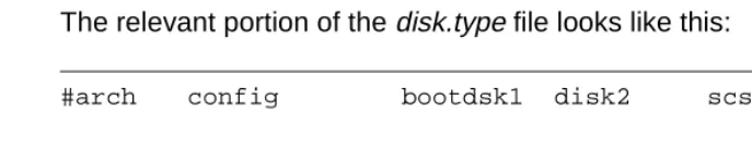
2The olds commands, which you will be using to configure the Solstice DiskSuite software, obtain information about your disk configuration from the /olds/disk.type file. If your boot disks are not as specified in the Disks table in Step 2, check the disk.type file to verify that it names the proper boot disks for your system.
The relevant portion of the disk.type file looks like this:
The bootdisk1 column designates the first boot disk; the disk2 column designates the second boot disk in a mirrored configuration. In order for the olds commands to work, the disks.type file must match your physical configuration: you must have disks in the locations specified in the file.
Step 5: Set up the
disk subsystem for
Solstice DiskSuite
21. Set the environment to the Korn Shell by entering these commands:
(where <ctrl-H> indicates you should press and hold the Control key as you press the H key).
The stty command sets up your backspace key as an actual backspace. If you do not enter this command, you will have to use the Delete key as a backspace.
2. Make sure the CMS CD is loaded in the CD-ROM drive.
3. Copy the Solstice DiskSuite setup scripts from the CD to the boot disk by entering the following commands:
4. Alter your path:
#arch config bootdsk1 disk2 scsi control #Enterprise 3000
sun4u notmirrored c0t0d0 c0t1d0 dontcare sun4u mirrored c0t0d0 c0t1d0 controllers=0
# stty erase <Ctrl-H> # ksh -o vi
# mkdir /olds
# cp /cdrom/cdrom0/cms/reloc/rdonly/olds_install/* /olds
# cd /olds
# chmod +x /olds/olds
5. Check the disks:
6. Create system files for the Solstice DiskSuite software:
7. Make sure all the disk drives on your system have been recognized.
To do that, read the file /olds/md.tab.new into an editor and locate the #/cms section. It should reflect the precise number of disk drives on your system. The following example shows a total of four disk drives on the system, two in d19 and two in d20:
If there is a discrepancy between what the system should have recognized and what it did recognize, complete the procedure in “The system fails to recognize all disk drives” on page 82, and then return to item 5.
# olds -mirrored -check_disks
number of external scsi controllers with disks is = 0
number of disks is = 4
. . .
disk:c0t0d0 is partitioned ok disk:c0t1d0 is partitioned ok disk:c0t2d0 is partitioned ok disk:c0t3d0 is partitioned ok Success, checking disks for mirroring.
#
# olds -mirrored -mk_files #
. . . #metaroot
d11 1 1 c0t0d0s0 d12 1 1 c0t2d0s0 d13 -m d11
#/cms
d19 2 1 /dev/rdsk/c0t0d0s3 1 /dev/rdsk/c0t1d0s1 d20 2 1 /dev/rdsk/c0t2d0s3 1 /dev/rdsk/c0t3d0s1 d21 -m d19
#metaswap
Step 6: Run the
setup scripts
21. Create the state database replicas by entering the following command:
2. Mirror the root file system by entering the following command:
3. Check disks with “metastat” and wait until all disks are synched.
Ignore any FSCK error messages which may be generated.
4. Reboot and log in as the root user (boot -r):
# olds -mirrored -metadbs .
. .
Success, setting up metadb replicas
# olds -mirrored -setroot .
. .
Success, root mirrored successfully.
# /usr/sbin/shutdown -y -g0 -i0 .
. . ok
ok boot -r . . .
<hostname> console login: root Password: <password>
#
5. Setup the /cms metadevices by entering the following commands:
6. Create and mount the /cms file system by entering the following commands:
Step 7: Verify disk
space
21. Display available disk space by entering a df -k command. The system responds with a file system table. For example:
The figures on the /dev/md/dsk/d21 line are critical. You will use them to determine whether DiskSuite is administering all your disks.
# ksh -o vi
# export PATH=$PATH:/olds # olds -mirrored -setup
. . .
3962848, 13997552, 14032256, 14066960, 14101664, 14136368, 14171072,
14205776, 14240480, 14275184, 14309888, 14344592, 14376992, 14411696,
14446400, 14481104, 14515808, 14550512, 14585216, 14619920, 14654624,
14689328, 14724032, 14758736, 14793440, 14828144, 14862848, 14897552,
14929952,
ufs fsck: sanity check: /dev/md/rdsk/d21 okay Success, /cms mirrored successfully
#
# mkdir /cms # mount /cms
# df -k
Filesystem kbytes used avail capacity Mounted on /dev/md/dsk/d13 772327 236870 458227 35% /
/proc 0 0 0 0% /proc
fd 0 0 0 0% /dev/fd
2. Complete the table below by filling in (1a) and (1b) as instructed.
3. Compare the figures in (1a) and (1b). They should be approximately equal. The two will not correspond exactly, but they should be within about 10% of the /cms size figure. A major discrepancy between the disk space you should have and the space recognized by the software usually indicates a connectivity problem. You can check connectivity by checking the output of a metastat command to see that all the disks are recognized. For example:
If the stripes of d19 and d20 do not account for all the disk drives on your system, check your disk drive connections. If discrepancies persist, telephone the Lucent National Customer Care Center at 1.800.242.2121, or contact your Lucent representative or distributor.
Disk Space Verification Total No.
of Disks
/cms size in MB (4-GB disks)
/cms size in MB
(9-GB disks) Calculations:
2 3104 6208 (1a) Enter /cms
line’s ‘kbytes’ figure divided by 1000 (move decimal
three places left): (1a)
4 7137 14274
6 11170 22340
8 15203 30406
10 19236 (1b) Enter “/cms
Size” (above left) corresponding to the number of hard
disks and disk size: (1b)
# metastat
. . .
d21: Mirror
Submirror 0: d19 State: Okay Submirror 1: d20 State: Okay
. . .
d19: Submirror of d21 State: Okay Size: 14398560 blocks Stripe 0:
Device Start Block Dbase State Hot Spare
c0t0d0s3 0 No Okay
Stripe 1:
Device Start Block Dbase State Hot Spare
c0t2d0s1 0 No Okay
d20: Submirror of d21 State: Okay Size: 14398560 blocks Stripe 0:
Device Start Block Dbase State Hot Spare
c0t1d0s3 0 No Okay Stripe 1:
Device Start Block Dbase State Hot Spare
Step 8: Install the
CMS software
2Now you will complete the installation of the usual software by installing CMS. In general, the steps are as listed below. Detailed installation instructions can be found in CentreVu CMS R3V8 Software Installation and Setup (585-210-941).
The steps to be completed are these:
● Install CMS software
● Install CMS patches (if needed)
● Install CMS Supplemental Services software
● Set up CMS
● Install Open Database Connectivity (ODBC) software (optional)
● Set up the remote console
● Administer the NTS (if using NTS ports)
Step 9: Create an
alternate boot
device
21. Enter the following command:
where newbootdev is the device name of the disk chosen as boot disk 2 (as c0t1d0s0, for example). You partitioned that disk earlier in the installation procedure.
The system responds (for example):
2. Record the device definition (the part after /devices and
before:a,raw). For the example above, you would record the part
beginning /sbus@3,0 and ending sd@1,0.
3. Reboot the system by entering the following command:
The system displays the ok prompt.
4. Create a device alias for the new boot device by entering the following command (for example):
Replace <device> with what you recorded in item 2. For the example shown, you would replace <device> with the following:
/sbus@3,0/SUNW,fas@3,8800000/sd@2,0 # ls -l /dev/rdsk/newbootdev
lrwxrwxrwx 1 root root 83 Jun 18 15:23 /dev/rdsk/c0t1d0s0 -> ../../devices/sbus@3,0/SUNW, fas@3,8800000/sd@1,0:a,raw
# /usr/sbin/shutdown -y -i0 -g0
5. Enter the following command:
6. Check the output for a line like this:
bootdevice2 <device definition>
where, again, <device definition> is the string recorded in item 2.
7. Verify that the system boots normally off the alternate boot device, and log in as the root user:
8. Reboot with a shutdown command and again log in as root:
9. Verify that everything is normal.
10. Enter the following command:
The system starts the editor and loads the cron file.
11. Add the following line to the end of the file:
15 0 * * * /olds/chkDisks > /dev/null 2>&1
12. Save the file and exit the editor.
ok devalias
ok boot bootdevice2 .
. .
<hostname> console login: root Password: <password>
. . . #
# /usr/sbin/shutdown -y -g0 -i6 .
. .
<hostname> console login: root Password: <password>
. . . #
13. Enter the following command:
14. Do a CMSADM backup. For instructions, see the CentreVu
CentreVu CMS R3V8 Administration (585-210-910) document or the maintenance and troubleshooting document for your hardware platform.
When the CMSADM backup is finished, the factory installation procedure for disk mirroring is complete.
3
Maintaining Mirrored Systems
3This chapter contains procedures you are likely to need to maintain a disk-mirrored system, including replacing disk drives, recovering from disk failures, and using the olds scripts.
Using the alternate boot device
3When you set up your mirrored system, you created an alternate boot device named bootdevice2.
The alternate boot device is a fail-safe device. If for some reason you are unable to boot from the primary boot disk—a corrupted boot disk, for example—you can tell the system to boot from the alternate device until further notice.
You do that by entering one of the following commands, depending upon whether you are at the boot prompt or in root:
_________________________________________________________________
ok setenv boot-device bootdevice2 # eeprom boot-device=bootdevice2
_________________________________________________________________ To reset the boot device to the primary disk, enter one of the following commands, again depending upon whether you are at the boot prompt or in root:
_________________________________________________________________
ok setenv boot-device disk # eeprom boot-device=disk
Maintaining the chkDisks crontab
3The chkDisks crontab runs each night and checks to see whether any potential or actual drive problems have been logged. The results of the search are logged to /olds/elog and mailed to the root user. This section shows how to start and stop chkDisks, and how to verify that it will run.
Activating
chkDisks
3Activate chkDisks by doing the following steps:
1. Enter the command: # crontab -e
The system starts the editor and loads the cron file.
2. Find the line for /olds/chkDisks. If it is commented out, uncomment it by deleting the pound sign at the beginning of the line. If there is no line for /olds/chkDisks, add the following line to the end of the file:
15 0 * * * /olds/chkDisks > /dev/null 2>&1
Verifying chkDisks
3 To verify that cron is running, enter the following command:Check the listing to see that there is an entry for chkDisks.
Changing the
scheduled run time
3The /olds/chkDisks line in the cron file is generally in the following format:
15 0 * * * /olds/chkDisks > /dev/null 2>&1
This line tells the system to run chkDisks every day at 15 minutes past hour zero, or 12:15 AM. You can change that schedule by changing the first five fields as necessary. The fields, in order of appearance, are: minute, hour, day of the month, month of the year, and day of the week. An asterisk means “all legal values.” For more information, see the manual (man) page for the crontab command.
Canceling
chkDisks
3To stop cron from running, enter the following command:
With the file loaded in the editor, comment out the entry for chkDisks and write and quit the file.
# crontab -l
Doing a CMSADM backup on a mirrored system
3This section describes how to perform a traditional CMSADM backup on a mirrored system.
Mirroring is intended as a way to minimize data loss should a system crash occur, not as a way to avoid backing up data. Mirrored systems must be backed up just as often as unmirrored systems.
Step 1: Print the
vfstab
file
3Print out the contents of the vfstab file before beginning the backup. You will need the information in that file to restore files from the backup tape.
To print the vfstab file, do the following:
1. Enter the following command:
2. Retrieve the printout and save it. You will need it again when the backup finishes.
Step 2: Run the
backup
31. At the system console, log in as root.
2. Verify that the computer is in a Solaris multi-user state (a run level of
2 or 3) by entering a who -r command. The system responds by listing the run level and date. For example:
If the system is in some other run level, reboot and log in again as the root user:
NOTE:
# lp /etc/vfstab
# who -r
. run-level 3 Feb 2 16:52 3 O S #
# /usr/sbin/shutdown -y -g0 -i6
. . .
<hostname> login: root password: <password>
. . .
3. Display the CentreVu CMS Administration menu by entering a
cmsadm command. For example:
4. Enter the number of the backup option. The system prompts for the tape drive.
5. Enter the appropriate option number. The system begins calculating the approximate number of tapes required and informs you of its calculation. For example:
6. Insert the tape, wait for it to rewind and reposition, and press Enter.
The backup begins.
During the backup, you may receive a prompt about CMS being on or prompts to insert more tapes. Respond to each prompt as appropriate, and then press Enter.
When the backup completes, it will be verified. If you used more than one tape, you will have to reinsert each tape.
Any time you need to insert a tape, allow it to rewind and reposition before you press Enter.
Step 3: Label and
store the tapes
3After the tape verification, the system prompts you to label the tapes and then returns you to the system prompt:
Label the tapes as instructed. Bundle them with the vfstab printout and put them away in a safe place.
# cmsadm
Lucent Technologies CentreVu(R) Call Management System Administration Menu
Select a command from the list below. 1) acd_create Define a new ACD
. . . .
The backup will need approximately 2 tapes. You will be prompted for additional tapes. Be sure to number the cartridge tapes consecutively in the order they will be inserted.
Please insert the first cartridge tape into /dev/rmt/<xxx>
Press ENTER when ready:
Please label the backup tape(s) with the date and the current CMS version (<version>).
Restoring from a CMSADM Backup
3This section contains the procedure for restoring /cms data files from a traditional CMSADM backup tape.
You may want to perform a CMSADM restore when, for example, your file systems are still intact, but some data has been corrupted.
If your CMS is running on a Sun Enterprise 3500, and you have had a crashed or corrupted disk, check the /kernel/drv/st.conf file before you begin the restore. Make certain the file contains the following entry:
# Begin CMS tape configuration list. tape-config-list=
"EXABYTE EXB-8900", "Mammoth EXB-8900 8mm Helical Scan", "EXB-8900",
"TANDBERG TDC 4200", "Tandberg 2.5 Gig QIC", "TAND-25G-FIXED",
"TANDBERG SLR5", "Tandberg 8 Gig QIC", "TAND-8G-FIXED"; EXB-8900 = 1,0x29,0,0xce39,4,0x7f,0x7f,0x7f,0x7f,0; TAND-25G-FIXED = 1,0x37,512,0x867a,1,0x00,0;
TAND-8G-FIXED = 1,0x37,512,0x963a,4,0xA0,0xD0,0xD0,0xD0,3;
# End CMS Tape configuration list.
If the file does not contain the entry, add it. The 3500’s Mammoth 8mm tape drive will not operate if the entry is absent.
To restore a CMSADM backup, do these steps:
1. Obtain the latest CMSADM backup tape.
2. Load the backup tape into the tape drive.
3. Enter the following command:
where <device> is one of the following:
/dev/rmt/0 The internal, noncompressing tape drive (14-GB, 8-mm drive) with the lowest target address.
/dev/rmt/1 The external, noncompressing tape drive (QIC-150 or 5-GB, 8-mm drive) with the second lowest target address.
/dev/rmt/0c The internal, compression-capable tape drive (usually a 14-GB or 40-GB) with the lowest target address.
/dev/rmt/1c The external, compression-capable tape drive (either a QIC 2.5-GB or a 14-GB tape drive) with the second lowest target address.
You may get error messages concerning the /home directory. These errors display when the directory is already present. Ignore them.
4. Restore any CentreVu CMS maintenance backups dated after the latest CDMADM backup. See the CentreVu CMS R3V8
Administration (585-210-941) document for details on restoring a maintenance backup.
Repairing or rebuilding the /cms file system
3This section contains procedures for reinitializing the /cms file system. You may need to perform this procedure in case of disk corruption or some other catastrophic system problem. The point of the procedure is to repair /cms or, failing that, to rebuild it and restore the latest available CMS data. Try to repair the file system first: if you can repair it, you will save considerable time and trouble.
Repairing
/cms
3 This procedure attempts to repair /cms.1. Turn off CMS.
a. Enter a cmsadm or cmssvc command. b. Select the run_cms option.
c. Select the Turn off CMS option.
2. Unmount /cms:
The system prompt should return without messages, as shown.
3. Do this step only if the umount command returned the response /cms: device busy.
a. Load the /etc/vfstab file into your editor.
b. Find the /cms and /cms/swap lines. Comment out both lines. (To comment out a line, insert a pound sign at the beginning.) c. Save the file and exit the editor.
d. Reboot by entering the following command:
4. Attempt to repair /cms:
# umount /cms #
# /usr/sbin/shutdown -i6 -g0 -y
# fsck -y /dev/md/rdsk/d21 ** /dev/md/dsk/d21
** Last mounted on /cms
** Phase 1 - Check Blocks and Sizes ** Phase 2 - Check Pathnames
** Phase 3 - Check Connectivity ** Phase 4 - Check Reference Counts ** Phase 5 Check Cyl groups
2060 files, 564453 used, 6468748 free (1900 frags, 808356 blocks, 0.0%
The system prompt should return without error, as shown above. (Of course, file and block counts in the last line will vary.) In that case, continue with the next step.
If you get an error message, however, repeat the fsck command. If the command still returns errors after 10 repetitions, stop this procedure and skip ahead to “Rebuilding /cms,” below.
Continue with step 6 only if you entered the fsck command and it returned the system prompt without error messages.
5. This step remounts /cms and reallocates the swap file. How that is done depends upon whether you altered the vfstab file earlier in this procedure.
If you altered the vfstab file earlier (step 4), do the following: a. Load the /etc/vfstab file into your editor.
b. Find the #/cms line. Uncomment the line. (To uncomment a line, delete the initial pound sign.)
c. Save the file and exit the editor.
d. Reboot by entering the following command:
If you did NOT alter the vfstab file, do the following: a. Remount /cms:
6. Turn on CMS:
a. Enter a cmsadm or cmssvc command. b. Select the run_cms option.
c. Select the Turn on CMS option.
The file system has now been repaired and should be operating normally.
If this procedure completed successfully, do NOT do the “Rebuild /cms” procedure.
Rebuilding
/cms
3 Do this procedure only if you have tried the fsck command at leastten times and it is still returning errors.
If you are running a Sun Enterprise 3500 platform, do not begin this procedure until you have checked the /kernel/drv/st.conf file to make sure the 3500’s 8mm tape drive is properly defined. See “Restoring from a CMSADM Backup” on page 43 for details.
To complete this procedure, you need the latest CMSADM backup. Also, /cms should still be unmounted at this point. If anything has been done to alter that, repeat steps 2 through 4 of the “Repairing /cms” procedure.
# /usr/sbin/shutdown -i6 -g0 -y
1. Add the Solstice DiskSuite directories to your path:
2. Detach the d20 submirror:
3. Clear the d20 submirror:
4. Clear the cms mirror:
5. Clear the d19 submirror:
6. Reinitialize the d19 submirror:
7. Reinitialize the d20 submirror:
8. Reinitialize the cms mirror:
# export PATH=$PATH:/usr/opt/SUNWmd/sbin:/olds #
# metadetach d21 d20
d21: submirror d20 is detached #
# metaclear d20
d20: Concat/Stripe is cleared #
# metaclear d21 mirror is cleared #
# metaclear d19
d19: Concat/Stripe is cleared #
# metainit d19
d19: Concat/Stripe is set up #
# metainit d20
d20: Concat/Stripe is set up #
9. Prepare the cms mirror for a new file system (this will take 15 to 30 minutes to complete):
10. This step remounts /cms. How that is done depends upon whether you had to alter the vfstab file when you attempted to repair the file system.
If you altered the vfstab file during the repair procedure, do the following:
a. Load the /etc/vfstab file into your editor.
b. Find the #/cms line. Uncomment the line. (To uncomment a line, delete the initial pound sign.)
c. Save the file and exit the editor.
d. Reboot by entering the following command:
If you did NOT alter the vfstab file, do the following: a. Remount /cms:
11. Verify that you are in the root directory.
12. Load the latest CMSADM backup tape into the tape drive.
13. Restore CMS data from the tape:
14. Restore the latest full maintenance backup.
# newfs -m 0 /dev/md/rdsk/d21 .
. .
14550512, 14585216, 14619920, 14654624, 14689328, 14724032, 14758736, 14793440, 14828144, 14862848, 14897552, 14929952,
ufs fsck: sanity check: /dev/md/rdsk/d21 okay Success, /cms mirrored successfully
#
# /usr/sbin/shutdown -i6 -g0 -y
# mount /cms
Restoring a mirrored system from a CMSADM backup
3This section shows you how to restore an entire mirrored system from a CMSADM backup. You might have to do this procedure, for example, if you have a disk crash that disables the operating system disk drive.
To do this procedure, you will need the “Solaris 7 3/99” compact disc and the most recent CMSADM backup tape. You will also need to know your system’s host name, host ID, and IP address.
Step 1: Power off
the system
3Power off the system by doing the following tasks:
1. Turn off the system unit.
2. Turn off the system monitor.
3. Turn off all external devices starting with the device closest to the system unit and working toward the farthest device.
Step 2: Install the
new drives
3 You must wear an ESD wrist strap when installing or removing hard disk drives to prevent electrical discharge that may harm system components.In Sun Enterprise 3xxx systems, the internal hard disk drives install in the front of the system. To expose the disk drive bays, open the front access door.
Each disk drive has a retainer latch/drive handle on the front of the drive. To install a drive, unlatch and extend the retainer and slide the drive carefully into the appropriate drive slot. When the drive stops, gently apply pressure to the face of the drive until you hear the connectors engage. Then lower the retainer latch and snap it in place, making certain the drive is secure and does not extend beyond the front of the chassis.
Do not use excessive force to seat the connector or to close the retainer latch.
For additional information about hard disks and disk drives, see the Sun System Reference Manual appropriate to your hardware platform.