-
--
- -
SY31
-
0462
-
0
-
--
--
----
-
-
----
_.--
-
--
- -
-
-
-
- -
-
-
--
----
-
-
----
-
..
--
-
•
-IBM 5256 Printer
Models 1, 2, and 3
SY31-0462-0
Preface
This maintenance manual is to be used for servicing the IBM 5256 Printer. Customer engineers using this r,
manual are assumed to have completed the 5256 Printer education course.
The maintenance manual is in two major sections; maintenance and theory. Maintenance includes locations, procedures, and diagnostic aids. Theory includes data flow, functional units, and features. Setup instructions for the 5256 Printer are in Appendix A.
Definition of terms and abbreviations that are not common but used in this manual are in the glossary and abbreviations section.
Related Publications
Related information can be found in the following manuals:
• IBM 5250 Display Station Reference Card,
GX21-9429
IBM 5251 Display Station Model 11 Maintenance
Analysis Procedures (MAPs), SY31-0571
First Edition (October 1977)
• IBM 5251 Display Station Model 11 Maintenance
Information Manual, SY31-0461
• IBM 5256 Printer Maintenance Analysis Procedures
(MAPs), SY31-0572
• IBM 5251 Display Station Operator's Guide,
GA21-9248
• IBM 5256 Printer Operator's Guide, GA21-9260
• IBM 5256 Printer Setup Procedures, GA21-9290
• IBM 5256 Printer IR Unit and Cause Code Guide,
ZY31-0505
Note: The following pages of the M I M have danger and caution notices. If desired, translate these
notices and write your own words on the blank lines provided on these pages:
1-10 1-46 1-16 1-58 1-24 1-62 1-32 1-63 1-36 1-64 1-37 1-67 1-44 4-23
The information in this manual is sometimes changed. Any changes will be given in later editions.
Requests for copies of IBM publications should be made to your IBM representative or the IBM branch office serving your locality.
A Reader's Comment Form is at the back of this publication. If the form has been removed. address your comments to IBM Corporation. Publications. Department 245. Rochester. Minnesota 55901. Comments become the property of IBM.
The IBM 5256 Printer has the following specific dangers:
• The print head becomes very hot during printing.
Primary power is present at the power supply and the Power switch.
• High voltage and current are present at the ferroresonant transformer.
Resistor 1 (in front under the safety cover) is very hot while power is on.
vi
CE SAFETY PRACTICES
All Customer Engineers are expected to take every safety precaution possible and observe the following safety prac· tices while maintaining IBM equipment:
1. You should not work alone under hazardous conditions or around equipment with dangerous voltage. Always advise your manager if you MUST work alone. 2. Remove all power, ac and dc, when removing or assem·
bling major components, working in immediate areas of power suppiies, performing mechanical inspection of pow-er supplies, or installing changes in machine circuitry. 3. After turning off wall box power switch, lock it in the
Off position or tag it with a "Do Not Operate" tag, Form 229-1266. Pu II power supply cord whenever possible. 4. When it is absolutely necessary to work on equipment having exposed operating mechanical parts or exposed live electrical circuitry anywhere in the machine, observe the fol.lowing precautions:
a. Another person familiar with power off controls must be in immediate vicinity.
b. Do not wear rings, wrist watches, chains, bracelets, or metal cuff links.
c. Use only insulated pliers and screwdrivers. d. Keep one hand in pocket.
e. When using test instruments, be certain that controls are set correctly and that insulated probes of proper capacity are used.
f. Avoid contacting ground potential (melal floor strips,' machine frames, etc.). Use suitable rubber mats, pur-chased locally if necessary.
5. Wear safety glasses when:
a. Using a hammer to drive pins, riveting, staking, etc. b. Power or hand drilling, reaming, grinding, etc. c. Using spring hooks, attaching springs. d. Soldering, wire cutting, removing steel bands. e. Cleaning parts with solvents, sprays, cleaners,
chemi-cals, etc.
f. Performing any other work that may be hazardous to your eyes. REMEMBER - THEY ARE YOUR EYES. 6. Follow special safety instructions when performing
special-ized tasks such as handling cathode ray tubes and extremely high volta'ges. These instructions are outlined in CEMs and the safety portion of the maintenance manuals. 7. Do not use solvents, chemicals, greases, or oils that have
not been approved by IBM.
8. Avoid using tools or test equipment that have not been ap-proved by IBM.
9. Replace worn or broken tools and test equipment. 10. Lift by standing or pushing up with stronger leg muscles
-this takes strain off back muscles. Do not lift any equip-ment or parts weighing over 60 pounds.
11. After maintenance, restore all safety devices, such as guards, shields, signs, and grounding wires.
-12. Each Customer Engineer is responsible to be certain that no action on his part renders products unsafe or exposes customer personnel to hazards.
13. Place removed machine covers in a safe out-of-the-way place where no one can trip over them.
14. Ensure that all machine covers are in place before returning machine to customer.
15. Always place CE tool kit away from walk areas where no one can trip over it; for example, under desk or table.
16. Avoid touching moving mechanical parts when lubricating, checking for play, etc.
17. When using stroboscope, do not touch ANYTHING - it may be moving.
18. Avoid wearing loose clothing that may be caught in mao chinery. Shirt sleeves must be left buttoned or rolled above the elbow.
19. Ties must be tucked in shirt or have a tie clasp (preferably nonconductive) approximately 3 inches from end. Tie chains are not recommended.
20. Before starting equipment, make certain fellow CEs and customer personnel are not in a hazardous position. 21. Maintain good housekeeping in area of machine while per·
forming and after completing maintenance. Knowing safety rules is not enough.
An unsafe act will inevitably lead to an accident. Use good judgment· eliminate unsafe acts.
ARTIFICIAL RESPIRATION
General Considerations
1. Start Immediately - Seconds Count
Do not move victim unless absolutely necessary to remove from danger. Do not wait or look for help or stop to loosen clothing, warm the victim, or apply stimulants. 2. Check Mouth for Obstructions
Remove foreign objects. Pull tongue forward. 3. Loosen Clothing - Keep Victim Warm
Take care of these items after victim is breathing by him-self or when help is available.
4. Remain in Position
After victim revives, be ready to resume respiration if necessary.
5. Call a Doctor
Have someone summon medical aid. 6. Don't Give Up
Continue without interruption until victim is breathing without help or is certainly dead.
Rescue Breathing for Adults
1. Place victim on his back immediately. 2. Clear throat of water, food, or foreign matter. 3. Tilt head back to open air passage.
4. Lift jaw up to keep tongue out of air passage. 5. Pinch nostrils to prevent air leakage when you blow. 6. Blow until you see chest rise.
7. Remove your lips and allow lungs to empty.
8. Listen for snoring and gurglings - signs of throat obstruc-tion.
9. Repeat mouth to mouth breathing 10-20 times a minute. Continue rescue breathing until victim breathes for himself.
Thumb and finger positions
Final mouth~to
mouth position
SAFETY . . . • . . . vi
GLOSSARY OF TERMS AND ABBREVIATIONS . . . xiii LEGEND . . . xvi
USING THE IBM 5256 MAINTENANCE INFORMATION MANUAL . . . • . xvii
Glossary of Terms and Abbreviations . . . . Maintenance. . . . . . " .. Wiring Diagram . . . .
Diagnostic Aids . . . . Preventive Maintenance .. . Tools and Test Equipment. Theory . . . .
Features . . . . Appendix A . Index . . . .
MAINTENANCE . . . . SEQUENCE-AFFECTED PROCEDURES. LOCATIONS . . . " . . . . 100 Front and Right Side Locations . . . .
xvii xvii xvii xvii xvii xvii xvii . . . xviii . . xviii . . . xviii
. . • . . . 1-1 . . . 1-1 .1-2 .1-2 101 Front and Left Side Locations. . . . . .1-3 102 Back Locations . . . 1-4 103 Printer Mechanism Bottom Locations (Print Mechanism
in Service Position) . . . .1-5 104 Printer Mechanism Base Locations. . . .1-6 105 Power Supply Board A 1 Locations and Jumpers. . . .1-7 106 Planar Board Bl Locations and Jumpers. . . . • . . . . .1-8 107 Power Adapter Board Cl Locations. . . .. 1-9 108 Cabling Locations and Station Protector . . . 1-10
Motor Cables (EC2 to TPBl and TPB2) .. 1-10
COVER . . . . . . 1-12 110 Printer Covers . . . 1-12 Adjustment . . . 1-12 Top Cover Removal and Replacement. . . .1-12 Back Cover Removal and Replacement . . . 1-12 Front Cover Removal and Replacement . . . 1-12 111 Control Panel and AC Cable Assembly . . . 1-13 Control Panel Removal and Replacement . . . 1-13 AC Cable Assembly Removal and Replacement . . . 1-13 SERVICE POSITIONS . . . 1-14 115 Separating the Printer From the Power Supply Board A 1
For Service Positions. . . 1-14 116 Moving the Power Supply for Printer Servicing . . . " .. 1-16 PART NUMBERS. . . 1-16 117 Boards, Card, I nterposers, and Jumpers. . . . 1-16 FORMS MOVING PARTS. . . .1-17 120 Platen and Paper Deflector . . . 1-17 Removal and Replacement . . . 1-17 121 Platen Latches (Release Eccentrics and Springs) . . . 1-18 Adjustment . . . " . . . 1-18 122 Platen Gears and Bushing. . . 1-18 Removal, Replacement, and Adjustment. . . 1-18
123 Platen Pressure Rolls . . . . Adjustment . . . .
124 Platen Gear Backlash (Play) . . . . Adjustment . . . . 125 Forms Motor Gear Backlash (Play)
Adjustment . . . . 126 Forms Motor and Emitter . Removal and Replacement .. Disassembly . . . . Assembly . . . . 127 Forms Feed Emitter Disk ..
Adjustment . . . . 128 Forms Motor to Emitter Timing ..
Service Check. Adjustment . . 129 A-Frame . . .
Service Check. Alignment . . .
130 End-of-Forms Switch .. Service Check . . . . Adjustment . . . ' .. . Removal and Replacement. . . . 131 Forms Tractor Unit . . . . .
Removal and Replacement . . . . Disassembly and Assembly . . . . Left Tractor Acljustment . . . . 132 Forms Tractor Unit Chain Cover ..
Service Check . . . .
Contents
· . 1-19 · . . . 1-19 · . . . 1-20 · . . . 1-20 · . . . 1-21 · . . . 1-21 · . . . 1-23 · . 1-23 .1-24 · .1-24 · . . . 1-25 · . . . 1-25 · . 1-26 · . . . 1-26 · . 1-27 · . . . 1-29 · • . . . 1-29 · . . . 1-29 · . . . 1-30 · . . . 1-30 · . . . 1-30 · . . . 1-30 . . . . 1-32 · . . . 1-32 · . . . 1-32 · . . . 1-33 · . . . 1-33 · . . . 1-33 Adjustment . . . . . . 1-33 133 Forms Tractor Unit Chain . . . 1-35 Removal and Replacement . . . 1-35 134 Forms Guide Rack Static Eliminator Replacement. . . 1-35 PRINTER EMITTER. . . 1-36 140 Print Emitter Board to Pickup and Amplifier Card . · .1-36 Service Check . . . . · . 1-36 Adjustment . . . · . 1-36 Printer Emitter Pickup and Amplifier Removal and
Replacement . . . 1-37 141 Print Emitter Board. . . 1-38 Removal and Replacement. . . 1-38
142 Print Emitter Hold Down Bracket. .. 1-38
Adjustment .. 143 Left Margin .. Service Check. Adjustment .. CARRIER . . .
150 Carrier Main and Support Shafts .. Service Check . . . . Adjustment . . . . 151 Carrier Support Shaft . . . .
Removal and Replacement. . 152 Carrier and Main Shaft . . .
Removal and Replacement . . 153 Belt Tensioner Assembly . . Removal and Replacement . 154 Carrier Motor and Pulley . .
Removal and Replacement ..
· . 1-38 . 1-38 · .1-38 · . 1-38 .1-40 · .1-40 · .1-40 · .1-40 · . 1-41 · . 1-41 · . 1-41 · . 1-41 · . 1-42 · . . . 1-42 · . . . 1-43 · • . . 1-43 · .1-43 155 Carrier Leaf Spring and Bearing
PRINT HEAD . . . 160 Print Head . .
Service Check.
Adjustment . . . .
· .1-44 · .1-44 · .1-44 · .1-44 Removal and Replacement. . . • . . . 1-44 161 Print Head Forms Guide . . . 1-45 Adjustment . . . . 1-45 Removal and Replacement. . . . 1-45 162 Print Head Cable (EC1). . . . . . 1-46 Removal. . • . . . . • . . . • . . . . . . 1-46 Replacement. . . • . . . 1-47 163 Oil Felt Service. . . • • • . . . . . . • 1-48 164 Print Head Ribbon Lifter . . • • . . . • • . . • • 1-48 Removal and Replacement . . . • . . . • . . . . • 1-48 165 Print Head Ribbon Shield . . . • • . . . • • 1-49 Service Check . . . • • • • . . • . • . . . • • 1-49 Removal, Replacement, and Adjustment . • • • . • • • . . . • 1-49 166 Copy Control Dial . . . • . • . • . . . • • • . • • . 1-51 Removal and Replacement . . . • • . . . • . . • . . . . • . 1-51 167 Print Head Retract Ramp. . . . . . 1·51 Adjustment. . . . .. . . . • . . . . . . . 1·51 RIBBON DRIVE . . . • . . . 1·52 170 Ribbon Drive . . . 1-52 Removal and Replacement. . . . . . 1-52 171 Ribbon Drive Clutches. . . 1-52 Removal and Replacement. . . 1-52 172 Ribbon Drive Shaft. . . 1-52 Removal and Replacement. . • . . . 1-52 173 Ribbon Drive Lines. . . • . . . 1-52 Removal and Replacement. . . . • . . . 1-52 174 Ribbon Feed Rolls. . . • . . . . . . 1-54 Service Check . . . . . . . 1-54
Adjustment . . . . . . 1-54 Removal and Replacement. . . . 1-54 175 Ribbon Drive Gears . . . • . . . • . . . 1-54 Removal and Replacement . . • • • . . . . • • • . • . . . 1-54 176 Ribbon Box and Cover . . • . . . • • • . ~ . . . 1-54 Removal and Replacement. . . • . . . . 1-54 177 Ribbon Changing . . . • . . . • . • . . . 1-55 . POWER AND ELECTRONICS • . • . • . • • • • • • . . . 1-57 180 Power Supply . • • . . • . • . . . • _ • • • . . . . • . . . 1-57 Removal and Replacement. . • • . . . • • • • . _ . . . 1-57 Ripple Level Check . . . . • • • • . • . . • . . . _ . __ • _ 1-57 181 Power Transformer . • • . . • • . . . • . . . 1-58 Removal and Replacement __ • . . • . • • • . • . . . . •••• 1-58 182 Fans . . . • . . . • . • • 1-60 Fan B1 Removal and Replacement . . . • . . . • • • 1-60 Fan B2 Removal and Replacement . . . 1-60 183 TB2 and Line Filter . . . 1-60 TB2 Removal and Replacement . . . 1-60 Line Filter Removal and Replacement. ~ . . . 1-60 184 Power Adapter Board C1 and Capacitor Assembly . . . 1-62 Capacitor Service Check. . . . . . 1-62 Removal and Replacement. . . . . . 1-62 185 AC Capacitor (C12) and Capacitor C3 . . . 1-63 C12 Removal and Replacement . . . 1-63 C3 Removal and Replacement. . . . . . . . . 1-63 186 Power Supply Board A 1 and Cable . . . 1-64 Removal and Replacement . . . 1-64 187 Transistor (Q1). . . . 1-65 Service Check. . . . . . 1-65 Removal and Replacement. . -. .
188 Planar Board B1 . . . . Removal and Replacement. . 189 Printer Wiring Diagram . . .
· . . . 1-65 · . . . 1-67 · . . . 1-67 . . . . 1-68
DIAGNOSTIC AIDS. · . . . 1-70 190 Power on Diagnostic . . . . · . . . 1-70 191 Offline Tests . . . . . · . . . 1-74 Print Test (PRT04) . . . . . . . . 1-74 Carrier Motor (PRT05) . . . . · . 1·75 Forms Motor (PRT06) .. . . . 1-75 Alignment (PRT07). . . .
Print Character Set (PRT08). . . Print Receive Buffers (PRT09) . Left Margin Recognition (PRT10) .
Printer Characteristics Display (PRT11) . . . . Data Storage (PRT12) . . . . Address Switches (PRT13). . . . . Set Transparent Mode (PRT14) . . . Print WireslTab (PRT15).
192 Online Tests . . . . Online Tests Overview . . . .
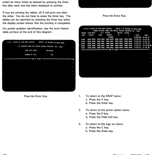
Matrix Printer Verification Test (Online Exerciser) •. Matrix Printer Verification Test Printout . . . . • • . Matrix Printer Verification Test (Online Exerciser)
· . 1-75 · . 1-76 · . . . 1-77 · . . . 1-77 · . 1-77 · . 1-78 · .1-78 · . 1-78 · . 1-79 · .1-80 · . 1·81 · .1-82 · .1-86 Printout in Transparent Mode (Partial) . . . 1.87 Fierd Definition of Error History Table (Sample Printout) . 1-88 193 Error Codes, Lights, Switches, and Test Points. . • . 1-89 Error Codes and Descriptions . . . . 1-89 Lights. . . . • . . . • . . . • . . . 1-90 Control Panel Switches. . . .. 1-93 Test Points. . . • . . . 1-93 195 Print Quality and Registration Problems . . . • . . 1·94 Print Quality Problem Examples . . . 1-94 Registration Problem Examples • . . . 1-95 196 Probe, Probing Information, and Interposer Check . . . 1-96 Probe Setup and Accessories. . . 1-96 Probe Power. . . 1-96 Probe Test . . . • . . . 1-96 Probe Light Conditions . . • . . . • . . . • . . . 1-96 Probing EC1, EC2, and C1A 1 . . . 1-96 Continuity Check for Interposers . . . 1-97 Removing Wire From Plugs P2, P3, P4, and P5 . . . • . 1-97 PREVENTIVE MAINTENANCE • • • • • • • . • . • . • . . . • • • 2·1 TOOLS AND TEST EQUIPMENT • • • • • • . . . . • • . . • • • • 3-1 General Logic Probe . . . 3-1 Standard CE Tool Kit . . . . . . 3-1 Metric Tool Kit . . . 3-1
THEORY • • • • • • • • . • • • • • • • • • . • • • • • • • • • • • • • 4-1 INTRODUCTION . . . '. . . . . . . .4-1 Printer Operation Overview and Data Flow . . . .4-2 System Configuration
Cable Adapter. . . . Frame Concept . . . . Transmission Sequences .. . Commands. . . . ~ . . . . Poll Response Frames ..
Read Status Response Frame . . . .
Printer SCS Formatting Control Characters . . . . Set Graphic Error Action Summary . . • . . . Set Horizontal Format Summary ..
Set Vertical Format Summary . . . . Interface . . . . Poll for Status. . . . Write Data . . .
Data Transfer . Microprocessing Unit . . .
Read/Write Storage. . Internal Processing Queues .. Control Panel and CE Lights . . .
Sense Latches. . . . . . . . Print Emitter Control and Print Timings . . . . Power and Signal Distribution . . . . Power On and Power Off Timings . . . .
Print Timings . . . . Printer to Adapter Interface. Functional Parts ..
Motors .. . Print Head .. .
Carrier· . . . • . . . Print Emiiter and Print Emitter Pickup .. . Ribbon Drive . . . .. . . . . . Forms Feed . . . .
.4-5 .4-6 .4-6 .4-7 .4-8 · . .4-9 · .4-10 · .4-11 · .4-12 · .4-12 · .4-13 · .4-13· · .4-13 · .4-13 • .4-14 · .4-15 · .4-15 · .4-15 · .4-17 · .4-17 · .4-18 · .4-20 · .4-20 . . . . 4-19 · . 4~22 · .4-23 · .4-23 · .4-25 · .4-33 · .4-34 • .4-36 · .4-37 Forms Tractor Unit . . . . . . . . 4-41 FEATURES . • • • . • • • • • . • • • • • • . . • • • . • • • . . • . • 5-1
Cable Thru. . . .5-1
Glossary, Seq. Affected, 0
Locations
Remove, Replace, Adjust
Wiring Diagram, Diagnostic Aids
Preventive Maintenance, Tools and Test Equipment
PM, Tools
o
Theory, Features
Appendix, Index
This list includes words and abbreviations used in the MAPs as well as those used in this manual.
A-frame: The part of the printer that supports the platen and pressure rolls.
ALU: Arithmetic and logic unit. amp: Amplifier.
amplifier (amp and AR): A device used to increase the size of a signal.
AR: Amplifier.
AR-DF: Differential amplifier.
AR-MD: Amplifier for driving magnets. ASCII: American National Standard Code for Information Interchange.
backiash: Gear play.
belt tensioner: The part that gives tension to the drive belt.
blows, blown (fuse): Open or opens. buffer: A small special storage device. C: capacitor.
carrier: The part of the printer that carries the print head and ribbon box.
CE: Customer engineer. chk: Check.
com: The common connection on a switch.
compression spring: A spring that is pressed into a small space so that it can supply force.
CR: Diode.
crooked: Skewed; not straight; sloping.
Glossary, Seq. Affected, Loc,;
Glossary of Tenns and Abbreviations
deflector: A part that moves something away. detenting: Locking.
dr: Drive.
EBCDIC: Extended binary coded decimal interchange code.
EC: Engineering change.
emitter: A device that generates pulses of electricity. EOM: End of message.
EOQ: End of queue.
E1, E2, E3: Print emitter pulses.
FB (fuse): A fuse that opens the circuit with no delay. FF: Form-feed switch.
FL: Latch (flip latch).
frame: A 16-bit group that carries information. FRU: Field replaceable unit.
GLP: General logic probe. gnd: Ground.
10: Identification.
interposer: A small connector with pins on both sides (see reference 196).
IRS: Interchange record separator. J: Jack.
LF: Line feed switch.
line turnaround: See the System Theory Maintenance Diagrams manual.
MAPs: Maintenance analysis procedures. MHz: Megahertz.
microprocessor: Microprocessing unit. MIM: Maintenance information manual. mini-MAPs: MAPs 0500 through 0516.
miscellaneous MAP: A MAP that guides you in replacing parts sequentially when all other MAPs have failed to locate the problem.
MPU: Microprocessing unit.
Multi: A switch setting on the general logic probe. N: Not (inverter).
N/C: Normally closed point of a switch. N/O: Normally open point of a switch. osc: Oscillator.
P: Plug
pickup: A device that senses electrical pulses. planar: The electronic board that contains the MPU, character generator, cable adapter, control storage, control panel adapter, printer adapter, data storage, and the offline tests.
poll, polled, polling: To question a station to determine if it is ready to send or to receive data.
POR: Power on reset.
power on transition bit: A bit sent to the controller to indicate that power is on in the printer.
pressure rolls: Rubber rollers that press paper against the platen of the printer.
prt: Print.
pulsing: A distinct change between the on and off conditions of the lights on the general logic probe. pwr: Power.
Q: A symbol for transistor. r: Reset.
reg: Register.
reinstall: Put back the part that was removed. remove: Take a part off the printer.
replace, replaced: Put a new part back in place of one that was removed.
retract ramp: The metal blade that moves the print head away from the platen when the carrier is moved as far as possible to the left in the printer.
ribbon drive lines: The material that is wrapped around the ribbon drive clutches to drive them when the carrier is moved.
s:
SetS8 (fuse): A fuse that opens the circuit after a delay. SCS: SNA character string.
SOLC: Synchronous data link control. serv: Service voltage or ground. short: Shorted or grounded circuit.
sideframe: A plate on each side of the printer mechanism.
SL T:. Solid logic technology. SNA: System network architecture. solid: A continuous failure or indication. SP: Stop.
ST: Start.
static eliminator: A printer part (reference 100
II>
that attaches to the forms rack. The static eliminatorremoves electrical c~arges that build up when the forms move through the printer.
stepper motor: A motor that moves in regular steps. synchronization: Two or more events occurring at the same time.
TPB: Taper pin block.
tractor chains: The parts on the tractor that protrude through the forms.
transition: Changing from active to inactive or from inactive to active.
twinaxial: A cable made of two twisted wires inside a shield.
Vac: Volts alternating current. Vdc: Volts direct current.
Glossary, Seq. Affected, Loc ..
Legend
o
( - - )
Decision Block
Information Block
Note Block
On-Page Connector
Off-Page Connector
Start or End of Flowchart
Using the IBM 5256 Maintenance InfonnationManual
The information in this manual is to be used as reference material when diagnosing machine failures. The maintenance information manual contains maintenance procedures, diagnostic aids, theory, and high level logics. An appendix gives general information that is not directly associated with the maintenance of the 5256 Printer (information such as setup procedures). This manual is engineering change controlled and will be revised as needed to give you the latest information possible for diagnosing problems.
The format for page numbering is X-YVY.Z. X is the section number, YYY is the page number, and Z (although not n.ormally used) is for expansion when it is not practical to give new numbers to all pages.
Reference methods used in the maintenance information manual are:
MAP 3-digit reference numbers -Page-to-page
On-page
MAP 3-digit reference numbers are assigned to location drawings and maintenance procedures to reference from the MAPs. For example, 127 indicates the forms feed emitter disk adjustment. Page-to-page references in a section are to the specific page containing the
information. For example, see page 4-15. On-page references are: this page, see below, ·etc. For figures with named or numbered parts, the reference is to the specific number or name of the part.
Glossary of Terms and Abbreviations
This section contains definitions of terms and
abbreviations that are not common, but are used in the M I M and MAPs.
Glossary, Seq. Affected, Loc ..
Maintenance
This section contains location drawings and maintenance procedures for repairing or installing FRUs that the MAPs diagnosed as failing. The location drawings are of 2 types: a reference drawing showing the major functional units, and detail location drawings showing the FRUs in a functional unit. Maintenance procedures are service checks, removals, replacements, and adjustments. All procedures have 3-digit reference numbers assigned to reference from the MAPs.
Wiring Diagram
A wiring figure shows point-to-point wiring between the individual electrical FRUs in the printer.
Diagnostic Aids
This section contains diagnostic program descriptions, how to use them, and what is available when they are in control. To aid in diagnosing machine failures in greater detail, a list if error conditions is included in this section.'
Preventive Maintenance
Parts needing regular service are described in this section.
Tools and Test Equipment
The tools needed to service the printer are described in this section.
Theory
The theory section contains descriptions of the functional units and features. These descriptions are preceded by a view of the system that gives you a general idea of the complete operation and where each function or feature fits in.
Features
The features section describes the operation of features for the printer.
Appendix A.
Appendix A contains the setup procedures.
Index
Sequence-Affected Procedures
Following is a list of sequence-affected procedures. Enter each list at any point, but perform all indicated operations from the entry point to the end of that list. 126 Forms Motor and Emitter Disassembly
125 Forms Motor Gear Bac~lash (Play) plus 127 Forms Feed Emitter Disk Adjustment 128 Forms Motor to Emitter Timing 124 Platen Gear Backlash (Play)
End
121 Platen Latches (Release Eccentrics and Springs) Adjustment or
129 A-Frame Alignment (see next list also) 124 Platen Gear Backlash (Play)
End
123 Platen Pressure Rolls Adjustment or 129 A-frame Alignment (see preceding list also) 130 End-Of-Forms Switch Adjustment
Glossary, Seq.
Affected, Lac ..
End
Maintenance
140 Print Emitter Board and Print Emitter Board to Pickup and Amplifier Card Removal and Replacement or
141 Print Emitter Board Removal and Replacement or
152 Carrier and Main Shaft Removal and Replacement 151 Carrier Support Shaft Removal and Replacement or 162 Print Head Cable Removal and Replacement or
140 Print Emitter Board and Print Emitter Board to Pickup and Amplifier Card Adjustment 143 Left Margin Adjustment
End
164 Print Head Ribbon Lifter Removal and Replacement or
166 Copy Control Dial Removal and Replacement or 160 Print Head Removal and Replacement
160 Print Head Adjustment End
Locations
100
FRONT AND RIGHT SIDE LOCATIONSII
Static EliminatorIII
Oscillator, J3II
Forms Tractor Unit RackII
Fine Adjustment Mounting ScrewII
RollersIE
Print Emitter Support..
Right Tractor Release Knobs1&
Carrier Motor and PulleyII
Address SwitchesII
Safety LableII
Cable ConnectorsIII
Safety CoverII
Audible Alarm'm
Guide (ribbon box)II
Paper-Advance KnobII
Print Head Retract Lever'B
Forms Tractor Drive GearfI1
Paper-Advance Knobm
TPB2fIl
Ribbon-Advance KnobIII
TPB1'til
Ribbon Release Lever (in operate position)101
FRONT AND LEFT SIDE LOCATIONS..
End-of- Forms SwitchII
Platen- Release Lever (Latch) (2)D
A-FrameII
Power SupplyII
PlatenII
Print Head Forms GuideII
Planar BoardII
Paper Release LeverII
Platen Gearsm
Idler GearIII
Ribbon BoxIE
Print Head CoverIII
Control PanelEnd-of-Forms Switch
COMO
N/ON/C
III
IE
m
II
lID
III
m
II
til
til
fI
m
m
Copy Control Dial
Connector EC3 (under the cover) Oil Felt
Carrier
Ribbon Drive Lines (2) Print Emitter Board Assembly Hold Down Bracket
Retract Ramp Drive Belt
Carrier Main Shaft Platen Pressure Rolls Connector J 1 Connector P1
---m
~----im
Top
802 002
~
EC3100,101
Glossary, Seq. Affected, Loc ..
102
BACK LOCATIONSD
B1A1II
B1B1II
B1C1..
B1D1II
Fuse F1 (3A, SB, part 2456618)II
Fan B2II
TB2 (line filter on some world trade machines)II
Line CordII
Terminal Block TB1IE
Transformer T1III
Power Adapter Board C1II
Capacitor C5 (+8.5V)II
Capacitor C12 (AC)III
Capacitor C4 (+5V)II
Terminator Switchm
Cable ConnectorsII
Address Switches (shown in the 0 position)IE]
Audible Alarm Volume Lever103
PRINTER MECHANISM BOTTOM LOCATIONS (PRINT MECHANISM IN SERVICE POSITION)..
Belt Tensioner PulleyII
Printer Emitter Pickup and AmplifierII
P2A..
J2II
P2BII
Ribbon Drive Clutches and GearsII
Carrier Drive BeltII
Print Emitter BoardII
Carrier Motor102,103
Glossary, Seq. Affected, Lac ..
III
J3 (See reference 100.)III
P3 (See reference 100.)III
Screw (to clamp printer in service position)III
Print Emitter Flat SpringsII
Belt ClampIE
Print Head Cable (EC1)m
Compression SpringII
Forms Feed MotorIII
Forms Feed Emitter104
PRINTER MECHANISM BASE LOCATIONS..
Power Supply Board A 1 (See reference 105.)III
Capacitor C1 (+10.8V)II
J4 (See reference 105.)III
TB3II
A1AlII
A1A4II
A1BlII
A183II
Capacitor C3 (+24V)IE
A1A3II
Capacitor C2 (+30V)II
Resistor RlII
Fan BlII
Transistor Ql105
POWER SUPPLY BOARD A1 LOCATIONS AND JUMPERSThe planar board has jumpers associated with character set, spee.d, and cable type. (See reference 106.)
Planar Interface Cable
From B1Al
Print Head
Cable (EC1) 002
e
lA
5 802
A 8 CRl
Test Points Toleranc&
Vl V2 V3 V4 V5 Wl W2 LMl LM2 FMA PMA G6;7 GS
+24 Vdc 24.6 Vdc 26.4 Vdc +30 Vdc 24.0 Vdc 36.0 Vdc +10.S Vdc S.l Vdc 13.5 Vdc +5 Vdc 4.6 Vdc 5.5 Vdc +5 Vdc 4.6 Vdc 5.5 Vdc -Wire on
Sets wire check (to adapter) +Left margin
Left margin (to adapter) +A forms drive +A carrier drive
Ground from A1A3 and A1A4 Ground from A1A4
\
21 Wire Check Jumper (normal position)
:
~~
S~~.
• V3 • V4 1 ·
• V5 J4 (white dot • G6 indicates • G7 position 1) • GS
22 Left Margin Jumper 15 (normal position)
~
\23
R3 \ 40 cps has resistor R3.
/ SO and 120 cps have jumper 23.
14
80ard Al
CR30~
~
2e
EC2e3
~C
,
013 To
40
~Cl
0
104,105
Glossary, Seq. Affected, Loc,.
To6
813
ECl
Rl
ge~e
CR2e
S 111111111111111111
CR4 6 I I
To 58 C2
,
\ \ \T04E 013
106
PLANAR BOARD B1 LOCATIONS AND JUMPERSPower supply board A 1 contains jumpers associated with speed and diagnostics. (See reference 105.)
CAUTION
When installing jumpers, they can cause a short circuit.
Language Group
o
4
00000 On (1)
%1111
Off (0)Plugged for U.S. and /
Canada /
(for other countries, see chart) /
/ / I Speed / / I /
%~
120 cps / I/ / Cable Type
I
..
II
II
To the address switches (Cable Thru feature only).
To the control panel.
To the audible alarm, board
A
1 A4, and board C1 (see note 2).II
To board A1A3 and board C1 (see note 2).II
Internal system cable;Notes:
1. Plugged only if the Cable Thru feature
is not
installed. 2.II
andII
are part of the planar interface cable. 3. This cable is polarity sensitive.Language Group
Bit
01234 Country
00000 U.S. and Canada 00001 ASCII (international) 00010 Austria and Germany 00011 Belgium
00100 Brazil
00101 Denmark and Norway 001 10 Finland and Sweden 001 1 1 France
01000 Italy 01001 Japan 01010 Portugal 010 1 1 Spain
01 100 Spanish Speaking 01 101 United Kingdom
o
1 1 1 0 Canada (French)o
1 1 1 1 Unused10000 Katakana 10001
I
I Reserved
I
I
1 1 1 1 0
1 1 1 1 1 Defaults to U.S. and Canada
I Probe Points I \ ~
I
\
'JI
(Seell',I
note 3) ,.I \
~I
40 cps Termination ,,
00
80 cps
00
o Unused
I
Twinaxial ~ (SeeCJ--e note 1)
107
POWER ADAPTER BOARD C1 LOCATIONS..
II
II
..
II
..
II
II
II
Transformer T1Fuse 2, 4A (5B-part 1143492) +30V (+24.0V to +36.0V)*
Fuse 3, 8A (5B-part 1146953) +10.8V (+8.1 V to +13.5V)*
Fuse 4, 6A (FB-part 303679) +5V (+4.6V to +5.5V)
Fuse 5, 3A (FB-part 855252) +8.5V (+7 .82V to +9.35V)
Fuse 6, 1A (FB-part 855253) -5V (-4.6V to -5.5V)
Voltage and signal connector Cl A 1 Probe power E18 (+)
Probe power E17 (-)
* Fuses 2 and 3 are in the return lines.
Connector C1A 1
Pin Line Pin Line
B02 Unused 002 -Power good B03 Power on reset 003 +5V B04 Ground 004 +5V B05 Ground 005 +5V B06 Ground 006 +5V B07 Ground 007 +5V BOB Ground OOB +5V B09 Ground 009 +5V Bl0 Ground 010 +5V Bll Ground 011 +B.5V B12 Unused 012 +B.SV B13 -SV 013 Unused
Board C1 Connections
Transformer T1 Wires C1 60 Hz (U.S.)
El
-E2
-E3
-E4 10 E5 11 E6 9 E7 19 EB 20 E9 lB El0 16 Ell I
17 E12 15 E13 7 E14 13 E15 E16
106,107
Glossary, Seq. Affected, Lac.
60 Hz (WT) 50 Hz (WT)
-
--
--
-14 16
15 17
13 15
23 25
24 26
22 24
20 22
21 23
19 21
11 13
17 19
J1 Other
+5Voutput Ground 1
5 Chassis Ground 6
[J
E16DJ
E15DE14
1'"ItIlIl".,,1
'I
?
E3
(]
fJ
0
0
0ij
E5
[ ] E13 [ ]
D[][]DfIll[]J[]
Rear- E12 Ell El0 E9 E8 E7 E6
0 - - - ·
108
CABLING LOCATIONS AND STATION PROTECTORMotor Cables (EC2 to TPB1 and TPB2)
When installing this cable, always install the wires from the new cable one at a time as you remove the corresponding wire from the old cable.
CAUTioN
Phasing is very important for the internal system cable and the Cable Thru feature wiring. Always connect the black-striped wire to the socket terminal beside the black dot, to the right-hand side of the Terminator switch, and to position 6 of the connector that attaches to the planar.
Note: For cable quality checks, refer to the controller documentation.
AC Cable Assembly Part of
Secondary AC Cable
(power to 1 O.8V and 30V supplies)
Address Switch Cable (Cable Thru feature only)
108
CABLING LOCATIONS AND STATION PROTECTOR (CONTINUED)See IBM 5250 Information Display System Installation Manual-Physical Planning, GA21-9277 for detailed informati on.
The station protector is owned and maintained by the customer. The following procedure can be used to check an IBM supplied station pro~ector.
The cables to the station protector must be
disconnected before the checks can be made. This will disconnect the work stations from the system.
I
DANGERNever handle cables or connectors during an electrical storm.
Typical Installation
System/ Controller
Building 1
Work Station
Station Protector Board
Outdoor Cable. ... 'Station / /
Protector
- - - 1
I
I
I
Cathode __
An 0
de---I
<-L ____ _
108
Glossary, Seq. -Affected, Loc ..
" , " ,
Only use CE meter part 1749231. Use the R x 100 scale.
1.
2.
Check each diode with the black lead connected to the anode and the red lead connected to the cathode. The resistance should be less than 2,000 ohms.
Check each diode with the black lead connected to the cathode and the red lead connected to the anode. The resistance should exceed 10,000 ohms.
Work Station
Work Station
Building 2
Work Station
Covers
110
PRINTER COVERSThe covers are designed to let you remove the top, front, or back cover individually. Paper can remain in the machine while removing covers.
Adjustment
1. Center the platen knobs vertically and maintain a gap of 3.18 mm to 3.96 mm (1/8 inch to 5/32 inch) between the top cover and the forms tractor by adjusting the pads in back
II
and the double nuts in frontII.
2. Position the printer horizontally on the double nut pins
II
to center th~ Paper-Release lever in the slot .. 3. Adjust the front cover by moving the bracket on each side of the machine base.
Top Cover Removal and Replacement
1. For ribbon changing and observation, slide the top cover
II
forward.2. To remove the top cover
D
slide it forward, lift it up, and remove it to the front.Back Cover Removal and Replacement
1. Loosen the faste·ners
II
and pull the back coverII
back to free the front coverII.
2. Lift the cover up and remove it to the rear.Front Cover Removal'and Replacement
You can pull the front cover forward enough to let you remove the platen without removing the back cover. 1. Move the back cover
II
back. (See above.) 2. Pull off the Horizontal Fine Adjustment knobB.
3. Press the release push buttonsII
on the sides ofthe front cover and slide the cover forward and off.'
111
CONTROL PANEL AND AC CABLE· ASSEMBLYControl Panel Removal and Replacement
1. Power off.
2. Disconnect the line cord from the wall outlet. 3. Remove the printer covers (110).
4.
5.
Disconnect the control panel cable at the planar board socket B1 C1
II.
.
Note the cable path and remove the cable to the control panel
II.
6. Loosen the 2 lower screws and remove the upper screw at each end of the panel support brackets
7.
8.
9.
II·
Remove the back panel
II
from the front panel (6 screws)II.
Remove the Power switch bracket
B
from the control panel (2 screws).Reinstall the control panel by reversing the procedure.
110, 111
Remove, Replace,
Adjust
AC Cable Assembly Removal and Replacement The AC cable assembly includes the Power switch and the fuse.
1. Power off.
2. Disconnect the line cord from the wall outlet.
3.
4.
. 5.
Remove the printer covers (110).
At the control panel, looserr the lower screw and remove the upper screw at each end of the panel support brackets
II.
Remove the Power switch shield
IE.
6. Remove the Power switch. •7.
8.
9.
Remove the fuse case
II.
Note the position of and remove the leads from TB2 (or the line filter) . . and TB 1
II.
Reinstall the cable by reversing this procedure. Note: Some world trade machines have a line filter in place of the terminal block.
i"
Service Positions
115
SEPARATING THE PRINTER FROM THEPOWER SUPPLY BOARD A1 FOR SERVICE POSITIONS
1. Power off.
2. Remove the printer covers (110).
3. Remove the 2 screws and the cable clamp" near EC1
II.
4. Disconnect the cables at EC1
II
and EC211. For installation, ensure the print head cable is against the flat spring.5. Disconnect J41J (white dot indicates position 1). 6. Remove the 2 screws
II
on the right end of theprinter.
7. Loosen the 2 screws
II
on the left end of the printer.8. Lift the right end of the printer slightly and slide the printer to the right to clear the screws
II.
9. Lift the printer from the power supply. If thebottom of the printer is to be serviced, remove the paper deflector and set the printer into the service position
II
on the base (so that the print emitterII
points upward). Hold the printer in this position with a base screwII
on" the left side and a base screwII
on the right side.Note: Operate the Ribbon-Release lever
II
to open the ribbon feed rolls; ensure that the ribbon box cover remains closed.10. To install the printer on the power supply, reverse this procedure.
1m!
Service PositionPower Supply
115
Remove, Replace., Adjust
Left End View
116
MOVING THE POWER SUPPLY FOR PRINTER SERVICING1. Power off.
2. Loosen the shipping screws
II
andII
seven turns. You may leave them loose except for shipping.3. Loosen the clamping screws
D D II
andIJ
one-half turn.4. Pull the power supply back, at the place shown, until screws" and
II
strike the stopsII
andII·.
5. To place the power supply in normal operatingposition, reverse this procedure.
D
Stand-off for Planar
Power Supply
Pull Here
I
TB2::f
Fanrl
L
Part Numbers
117 ,
BOARDS, CARDS, INTERPOSERS, AND JUMPERSBoards Part
Planar Board B1 (See
Gi§~
the caution.)
Power Adapter Board C1 4176517 Power Supply Board A 1 1638818 Print Emitter 1638711 Cards
A1A1 5863340
A1B1 5863342
A1B3 5863341
Print Emitter (pickup) 843202 Interposer 2731011
Jumper 1794401
CAUTION
The logic on planar board B 1 can be damaged by electrostatic discharge. Do not touch any conducting (metal) parts. Hold the planar by the plastic frame when moving it.
. Forms Moving Parts
120
PLATEN AND PAPER DEFLECTORRemoval ,and Replacement 1. Power off.
2. Center the print head on the platen. 3. Tilt the forms tractor back.
4. Pull the front cover forward to the stop (110). 5. To remove the platen, lift up on the Platen knobs
while pressing down on the Platen-Release levers
D·
6.
Lift out the paper deflectorII.
«
~~.
i~
II I
D
I7.
8.
To install the platen:
a. If the Paper-Release lever ~ is back, pull it forward.
b. Ensure that the paper deflector
I!i
is seated correctly with tabs ~ engaging the locating armslID
(both ends). Bend the tabs!II
to engage the locating armsa
if needed. c. Center the print head on the platen. d. Align the groovea
in the gear end of theplaten shaft with the side plate. Then, press down on both ends of the platen. Ensure that the gears engage correctly.
e. Ensure that the Platen-Release levers are . completely seated.
f. Turn the platen to check for binds.
Close the front cover and tilt the forms tractor forward until the arms engage the platen shaft.
Note: The locating arms
II
may need bending to ensure 0.51 mm (0.020 inch) between the paper deflectorII
and the tip of the print head when the Copy Control dial is set to O.~~
____ ---m
116-120
Remove. Replace. Adjust
121
PLATEN LATCHES (RELEASE ECCENTRICS AND SPRINGS)Adjustment
This procedure adjusts both the left and right eccentrics. However, when adjusting the left eccentric, ensure that the Platen Release lever does not touch the print head forms guide· (1 01) when the carrier moves to the far left.
1.
2.
3.
4. 5.6.
7. 8. 9. Power off.Remove the forms tractor (131). Remove-the printer covers (110).
Loosen, until it is finger tight, the screw
II
that locks the eccentric nutII.
Note: When adjusting the right side, remove the Platen knob and forms tractor drive gear. When installing, adjust gap to bushing
II.
Press the platen bushing" down and turn the eccentric nut so that when released, the lever holds the bushing tightly against the frame. Hold the eccentric nut in this position and tighten the locking screw.
Check the platen gear backlash (play) adjustment (124).
Reinstall the printer cover (110). Reinstall the forms tractor (131).
Left Side Right Side
Lever Spring (small)
Make sure that the print head forms guide does not strike the paper release lever here when the head moves to the extreme left.
Lever Spring (large)
122
PLATEN GEARS AND BUSHINGRemoval, Replacement, and Adjustment 1. Power off.
2:
3. 4.5.
6.
7.
Tilt the forms tractor back.
Pull the front cover forward to the stop and remove the platen (120).
Remove the knob from the gear end of the platen (2 setscrews
lIP.
Loosen the clamp collar
II
on the forms tractor drive gear.For installation, the bushing
II
must turn freely with 0.05 mm to 0.13 mm (0.002 inch to 0.005 inch) gap to the gear collar.Remove the gear
II
and bushingII·
8. Remove the 2 screws
II
that hold the platen gear. 9. Remove the gearII.
10. To reinstall the gears, reverse this procedure.
,..---0
,...---m
,."
,
I,..---0
,..---IJ
/-0
I ,
~
O.05mmtoO.13mm123
PLATEN PRESSURE ROllSAdjustment
Adjust the paper-release shaft
II
so that the Paper-Release leverII
gives a maximum pressure roll opening when the lever is forward. If the gap between the cam followerB
and the camII
is 0.05 mm to 0.51 mm (0.002 inch to 0.020 inch) when the lever is back, the adjustment is correct.Adjust the pressure roll arms
D
for a strong hold and no gap between the pressure rollsII
and the platen, when the Paper- Release lever is back.1.
2.
Power off.
Remove the printer covers (110), platen (120), tractor assembly (131), and the paper deflector.
3.
4.
5.
Adjust the paper release shaft
II:
a. Push the Paper-Release leverII
back.b. Loosen the 4 clamp collars
II
along the paper release shaft.c. Place a 0.38 mm (0.015 inch) gauge on the cam
II
and hold it there by pressing the cam followerB
on the gauge.d. Pivot the clamp collars so that the bell cranks
II
seat on the bottom of the 4 openings; then tighten the 4 clamp collarsII.
e. Remove the gauge, check the adjustment, and adjust again if needed.
Install the platen and paper deflector (print head centered on the platen).
Adjust the pressure roll arms:
a. Loosen the 2 nuts
D
that hold 1 set of pressure roll arms.b. Move the arms as needed to remove gap between any of the pressure rolls and the platen.
c. Check the adjustment, adjust again if needed. d. Check the adjustment of pressure rolls for the
other half of the platen; adjust if needed, using the preceding steps.
6. Check the adjustments for platen gear backlash (play) (124) and the End-of-Forms switch (130); correct them if needed.
7. Reinstall the printer covers (110).
0.05 mm to 0.51 mm
(0.002 inch to 0.020 inch)
121-123
Remove, Replace,
Adjust
124
PLATEN GEAR BACKLASH (PLAY)Adjustment
The idler and platen gears should have slight backlash (play) throughout their rotation. Engaging the gears at a
high point, such as that which occurs in line with a hole
II '
results in correct backlash (play) at other locations.1. Power off.
2. Remove the printer covers (110).
3. Loosen the 3 forms motor and emitter mounting screws
II.
4. Turn the gears so that a hole
II
in the idler gear is aligned with the gear shafts as shownII.
5. Position the motor up and back so that the gearsengage tightly.
6. Tighten the mounting screws.
7.
Check for no binds and adjust again if needed. 8. Reinstall the printer covers (110).125
FORMS MOTOR GEAR BACKLASH (PLAY)Adjustment 1. Power off.
2. Separate the printer from the power supply and place the printer in the service position (115). 3. Remove the forms motor and emitter assembly
(126).
4. Loosen the 2 screws and the nut
II
(bolt head access through hole in the idler gear) that holds the emitter baseB
on the motor.5. Turn the gears as needed so that a hole
II
in the idler gear is aligned with the gear shafts as shownII·
6. Turn the emitter base
B
on the motor so that the gears engage tightly.7. Tighten the 2 screws and the nut
II.
8. Check for binds and adjust again if needed. 9. Reinstall the forms motor and emitter assembly. 10. Adjust the platen gear backlash (play) (124). 11. Assemble the printer and power supply (115).~,/
II
124,125
o I
I I
I
Remove, Replace, Adjust
126
FORMS MOTOR AND EMITTERRemoval and Replacement 1. Power off.
2.
3.
4.
For installation, if the motor and emitter assembly was. disassembled, perform the forms motor to emitter timing (128).
Disconnect J4 on the power supply board A 1 (105).
Disconnect the motor leads from TPB2
II.
5. Separate the printer from power supply board A 1and place the printer in the service position (115).
126
Blue
1 - + - - -Fra me
I I I I 0--0-0
8
CBA
Remove. Replace.
Adjust
6.
7.
For installation only. adjust the platen gear backlash (play) (124) and return here. While holding the forms motor and emitter assembly, remove the 3 mounting screws from the right side frame
II.
8. Remove the motor and emitter assembly. To remove any parts from the motor and emitter assembly •. disassemble it as needed (126).
9. To reinstall the motor and emitter assembly, reverse this procedure.
D
126
FORMS MOTOR AND EMITTER (CONTINUED)Disassembly 1. Power off.
2.
3.
Remove the forms motor and emitter from the side frame (126).
Remove the emitter outer cover
IEJ.
4. Loosen the clamp collarlB.
5.
6.
7.
Remove the 2 adjusting screws
D
from the back of the base.Remove the screw that holds the photocell assembly
ID
and remove the photocell assembly. CAUTIONDo not use force on the disk; doing so will bend or scratch it.
Remove the inner cover
lEI
and the disk and gear assembly from the motor shaft by using force on the motor gear as shown.8. Remove the clip
II
that holds the idler gearII
and lift off the gear.. 9. Remove the 3 screws
II
plus the bolt and nutII
that fasten the baseII
to the motorII.
10. To put the motor and emitter together, use the assembly procedure.
Assembly
1.
2.
Install the 3 screws
II
plus the bolt and nutII
that fasten the baseII
to the motorII.
Do not tighten the screws and bolt now.Install the idler gear
II
with the longest hub toward the motor and install the clip.3. Install the inner cover
lEI
with the 2 adjusting screwsD
finger tight.4. Place the photocell assembly
III
on the disk and , gear assemblyII
and slide them on the motorshaft.
5. Fasten the photocell assembly with its mounting screw.
6. Center the forms emitter disk in the opening. Do not scratch black paint from around the disk holes. A 0.76 mm (0.030 inch) thickness gauge should slide freely on the upper side of the disk. Check the gap at several points on the disk.
7. Tighten the clamp collar
IE
and check the gap. 8. . Turn the gears so that a hole in the idler gearaligns with the gear shafts. Then turn the emitter base
II
on the motor so that the gears engage tightly.9. Tighten the screws and nut, and check play in several positions of the idler gear. Adjust again if needed.
10. Install the outer cover ~.
127
FORMS FEED EMITTER DISKAdjustment
The disk should be centered in the photocell assembly opening for all positions of the disk.
1. Remove the forms motor and emitter assembly (126).
2. Remove the outer cover
1m .
3. Loosen the clamp collar
m
and center the disk in the opening. Do not scratch the black paint from around the disk holes. A 0.76 mm (0.030 inch) thickness gauge should slide freely on the uppersi~e of the disk. Check the gap at several points on the disk.
Forms Feed Motor (rotated 900 clockwise)
126, 127
Remove, Replace,
Adjust
4. Tighten the clamp collar and check the gap.
5.
Reinstall the outer cover.6. Reinstall the motor and emitter assembly (126).
~ ~
0.63 mm to 0.88 mm I (0.025 inch to 0.035 inch)Ddl
128
FORMS MOTOR TO EMITTER TIMINGService Check 1. Power off.
2. Remove. the printer cover (110).
3. Lock the motor by connecting a jumper wire between test points FMA and G7
II
('forms motor drive A' to 'ground').a. Move the black wire from TP82-6C to TP82-3C
II.
b. Move the red wire from TP82-58 to TP82-6C
II·
4. Connect the probe power wire (red) to test point C1 E18 and the black wire to C1 E17 (196). 5. Probe 8181007 with the probe ground wire on
test point G8
II.
6. Power on.7. Verify the adjustment as follows:
.
.8.
a. At a Platen knob, use a small amount of force in the direction to move the forms up. The probe should remain at the up level when you remove your hand from the Platen knob. b. At a Platen knob, use a small amount of force
in the direction to move the forms down. The probe should remain at a down level when you remove your hand from the Platen knob . If the timing is not correct, go to the adjustment procedure. Otherwise continue as follows: a. Power off.
b. Move the red wire from TP82-6C back to TP82-58
II.
c. Move the black wire from TP82-3C back to TP82-6C
II.
Adjustment
1. Do steps 1, 2, and 3 of the service check and return to step 2 in this procedure.
2. Loosen the photocell assembly (2 screws
II
behind the motor) so that the assembly will slide but not move by itself.3. Connect the probe power wire (red) to test point C1 E18 and the black wire to C1 E17 (196). 4. Probe B1 B1 D07 with the probe ground wire on
test point G8
B.
5. Power on.6. Slide the photocell down as far as possible.
7. Slowly slide the assembly up until the probe up light comes on.
Note: If the up light is on with the photocell down as far as possible, slide the assembly up until the up light goes off and then comes back on.
a. Hold the photocell assembly tightly in place and tighten the 2 screws
II.
b. Verify the adjustment as follows:
At a Platen knob, use a small amount of force in the direction to move the forms up. The probe should remain at the up level when you remove your hand from the Platen knob.
At a Platen knob, use a small amount of force in the direction to move the forms down. The probe should remain at a down 'Ievel when you remove your hand from the Platen knob.
c. Adjust again if needed. d. Power off.
e. Move the red wire from TPB2-6C back to TPB2-5B
II.
f. Move the black wire from TPB2-3C back to TPB2-6C
II.
8. Remove the probe and the jumper wire.
9. Reinstall the printer covers and forms tractor unit.
128
Remove, Replace,
Adjust
Blue/White
Blue Frame
I
_ _ .r--=-<" I I
I
~8D
129
A-FRAMEA-frame alignment to the platen is set at the factory and mounting screws are sealed with Loctite'.
Alignment should not be needed in normal printer use. However, if alignment is needed, use the following procedure:
Service Check
1. Set the Copy Control dial to
o.
2.
3.
Run PRT04 (191) and check for uniform printing and density at both ends of the line.
Adjust if needed.
Alignment
1. Power off.
2. Remove the printer cover (110). 3. Set the Copy Control dial to
o.
4.
5.
Measure the gap between the platen and the print head at both ends of the platen. Gap should be 0.30 mm to 0.36 mm (0.012 inch to 0.014 inch). If the left end dimension is not correct, go to the next step; if the right end dimension is not correct, go to step "9.
If the left end dimension is not correct, slightly loosen the 2 A-frame mounting screws in the left side frame
e.
'Trademark of the Loctite Corp"
129
Remove, Replace, Adjust
6. With a brass punch and a hammer, tap on the . A-frame left side plate to obtain the specified gap. 7. Tightly fasten the A-frame mounting screws
(Loctite is not needed), check the gap, and adjust again if needed.
8.
9.
Check the gap at the right end of the platen. If the gap is not correct, continue on to the next step. If the gap is correct, install the printer cover (110), power on, and set the Copy Control dial for correct printing.
If the right end dimension is not correct, slightly loosen the 2 A-frame mounting screws in the right side frame
O.
10. With a brass punch and a hammer, tap on the A-frame right side plate to obtain the specified gap.
11. Tightly fasten the A-frame mounting screws (Loctite is not needed), check the gap, and adjust again if needed.
12. Check the gap at the left end of the platen. If the gap is not correct, return to step 5. If the gap is correct, install the printer cover (110)' power on, and set the Copy Control dial for correct printing. 13. Check platen gear backlash (play) (124) and adjust,
if needed.
14. Check the End-of-Forms switch adjustment and correct it if needed.
130
END-Of-fORMS SWITCHService Check
1. Set your CE meter to the R x 1 scale.
2.
3.
Connect the meter wires to the normally open (N/O) and the common (C) terminals of the switch
II.
Insert a 0.076 mm (0.030 inch) thickness gauge between the top of the actuator lever and the bottom of the platen groove. The meter should show that the switch has operated.
Note: The gauge must be held horizontal and not inserted too far or the indication will not be correct.
4. Check (by operating the Paper-Release lever several times) that the override arm operates the End-of-Forms switch.
5. Adjust if needed. Adjustment
1. Power off.
2. Remove the printer covers (110). 3. . Remove the forms tractor unit.
4. Remove the paper deflector and install the platen.
5.
6.
7.
8.
9.
Pull the Paper-Release lever toward the platen and leave it there.
Check that the switch actuator lever is centered in the platen groove
II.
If it is not centered, loosen the switch assembly mounting screwII
and place the switch assembly in position again. Fasten the screw tightly.Set your CE meter to the R x 1 scale.
Connect the CE meter leads to the normally open (N /0) and the common (C) terminals of the switch
II.
Loosen the 2 switch mount holding screws
0,
and move the switch mountII
toward the front of the printer.10. Insert a 0.076 mm (0.030 inch) thickness gauge between the top of the actuator lever and the bottom of the platen groove. Slowly push the switch mount toward the rear until the meter indicates that the switch has operated.
Note: The gauge must be held horizontal and not inserted too far or the adjustment will not be correct.
11. Tighten the screws
0
and check the adjustment. 12. Remove the platen.13. Reinstall the paper deflector and the platen. 14. Operate the Paper-Release lever several times to
check that the override arm operates the
End-of- Forms switch. If the switch operates, skip steps a through~. If the switch does not operate: a. Move the Paper-Release lever backward.
b. Place 0.30 mm to 0.50 mm (0.012 inch to 0.020 inch) of paper between the platen and actuator lever
B.
c. Loosen the setscrew
II
and move the override armII
so that the end of the arm touches, but does "lOt. move, the End-of-Forms switch actuator leverB.
d. Tighten the setscrew. e. Check the adjustment. 15. Reinstall the printer covers (110).
Removal and Replacement 1. Power off.
2.
3.
4. 5.6.
7.Remove the printer covers (110).
Remove the End-of-Forms switch assembly by removing the screw and the lockwasher
II.
Remove the switch from the assembly by removing the 2 screwsII.
Move the switch leads from the old switch to the new switch (N/C and C)
II.
Install the new switch on the assembly and install the assembly on the printer.
~D
C
N/O N/Co
"
'"
..