124
Comparative Study of Shopping Mall in Different
Seismic Zones Using Response Spectrum Analysis
Prasad R. Gayaki
1, G. P. Deshmukh
21
PG Student, Structural Engineeirng, Pankaj Laddhad Institute of Technology and Management studies, Buldhana
2
Head of Department, Department of Civil Engineering, Pankaj Laddhad Institute of Technology and Management studies, Buldhana
1
Abstract-Earthquake is very severe problem nowadays. As the shopping malls are having large amount of rush
daily so such type of the building should be earthquake resistant. We are going to study the behavior of commercial building against seismic load. A comparative study is carried out using ETABS software in different seismic zones using response spectrum analysis then finally it is concluded that what is the exact difference in the different earthquake zones having different intensities. Different parameters are compared using graphical and tabular form.
Index Terms- Shopping mall; ETABS; Response spectrum analysis;
1. INTRODUCTION
Today there is very severe problem in whole world about earthquake. The earthquake is the most hazardous natural disaster. The earthquake is sudden movement caused in earth crust with release of stress. Most of the commercial buildings such as shopping malls and multiplexes have large amount of rush daily so they should be earthquake resistant. So we are going to analyze the shopping mall in different seismic zones to compare their behavior in different seismic zones. ETABS software is used and method of analysis is response spectrum analysis.
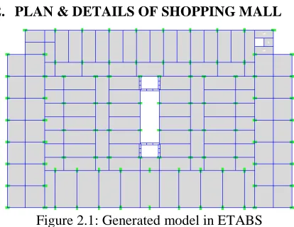
[image:1.595.76.283.491.651.2]2. PLAN & DETAILS OF SHOPPING MALL
Figure 2.1: Generated model in ETABS
This is the model of shopping mall generated in ETABS. Medium soil is taken, floor to floor height is 4m, total height of building is 25m, there are shops of area 28 sq.m. each size of the building is 55 x 33.4m.
3. ANALYSIS OF MODEL
Response spectrum analysis is done in ETABS software which is one of the dynamic analyses. Response Spectrum analysis allows the users to analyze the structure for seismic loading. Building with regular or nominally irregular plan configuration may be modeled as the system of masses lumped at the floor levels with each mass having one degree of freedom, that of lateral displacement in the direction under consideration. In such case, the following expressions shall hold in the computation of various quantities.
1) The modal mass (
M
k) of mode k is given by∑
∑
= =
=
ni
ik i n
i ik i
k
W
g
W
M
1
2 1
2
)
(
]
[
φ
φ
2) The modal participation factor (
P
k) of mode k is given by∑
∑
= =
=
ni
ik i n
i ik i
k
W
W
P
1
2 1
)
(
φ
φ
3) The peak lateral force (
Q
ik) at floor i in mode k is given by
125
4) The peak shear force (
V ) acting in the
ikstorey i in mode k is given by
∑
= ==
=
ni j
ik ik
Q
V
1
5) The peak storey shear force (
V
i) in storey i due to all modes considered is obtained by combining those due to each mode in accordance with clause 7.8.4.4 of code.
6) The design lateral forces,
F
roof andF
i, at roof andat floor i is given by
F
roof=
V
roof1
−
−
=
i ii
V
V
F
In the present work, Response spectra of IS1893:2002 is used. The method of Square root of sum of square (SRSS) is used for combining modal response. Damping factor is taken as 1, this corresponds to the 5% damping ratio. Spectra is applied in both X and Y direction.
4. LOAD COMBINATIONS
Following load combinations are used specified by IS 1893:2002 as per clause 6.3.1.2
1. 1.5(DL+LL) 2. 1.2(DL+LL+EL) 3. 1.5(DL+EL) 4. 0.9DL+1.5EL
5. RESULT
Response spectrum analysis is carried out on the model for all four seismic zones. The results are presented in the form of tables and graphs. Response Spectrum analysis allows the users to analyze the structure for seismic loading. In response spectrum method the peak response of the structure is calculated from modal combination.
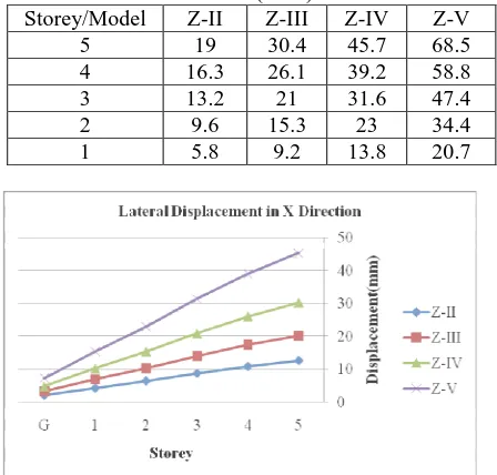
5.1 Lateral displacement
A graph is plotted taking floor level as the abscissa and the displacement as the ordinate, for different models in the transverse and longitudinal direction as shown in figure 5.1.1 and figure 5.1.2. The lateral displacement values in tabular form for longitudinal direction and for transverse direction are given in table 5.1 and 5.2 respectively.
Table 5.1.1: Displacement values in longitudinal direction (RSA)
Storey/Model Z-II Z-III Z-IV Z-V 5 12.6 20.1 30.2 45.3
4 10.8 17.3 26 39
[image:2.595.306.530.227.441.2]3 8.7 13.9 20.8 31.3 2 6.4 10.2 15.3 22.9 1 4.2 6.8 10.2 15.3
Table 5.1.2: Displacement values in transverse direction (RSA)
[image:2.595.306.523.478.615.2]Storey/Model Z-II Z-III Z-IV Z-V 5 19 30.4 45.7 68.5 4 16.3 26.1 39.2 58.8 3 13.2 21 31.6 47.4 2 9.6 15.3 23 34.4 1 5.8 9.2 13.8 20.7
Figure 5.1.1: Displacement profile in longitudinal direction (RSA)
Figure 5.1.2: Displacement profile in transverse direction (RSA)
126 displacement is up to 260% as compared with model I
(EQZ-II) in both longitudinal and transverse direction. Also it is observed that from zone II to zone III this increment is 60% whereas from zone III to zone IV and from zone IV to zone V it is 50%. This shows that consideration of proper seismic zone highly influence the analysis and design of structure.
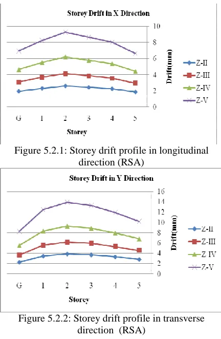
5.2 Drift
[image:3.595.305.521.96.427.2]A graph is plotted taking floor level as the abscissa and the storey drift as the ordinate for different models in the transverse and longitudinal direction as shown in figure 5.2.1 and figure 5.2.2. The storey drift values in tabular form for longitudinal direction and for transverse direction are given in table 5.2.1 and 5.2.2 respectively.
Table 5.2.1: Storey drifts values in longitudinal direction (RSA)
Storey/ Model Z-II
Z-III Z-IV Z-V Allowa -ble limit Rema rk 5 1.8 44 2.9 48 4.4 24 6.6
36 16 OK
4 2.2 28 3.5 64 5.3 48 8.0
24 16 OK
3 2.4 08 3.8 52 5.7 8 8.6
68 16 OK
2 2.5 8 4.1 28 6.1 92 9.2
88 16 OK
1 2.2 88 3.6 64 5.4 96 8.2
4 16 OK
Table 5.2.2: Storey drifts values in transverse direction (RSA)
Storey/ Model Z-II
Z-III Z-IV Z-V Allowa -ble limit Rema -rk 5 2.8 24 4.5 28 6.7 92 10.
184 16 OK
4 3.3 08 5.2 92 7.9 36 11.
908 16 OK
3 3.6 92 5.9 08 8.8 6 13.
292 16 OK
2 3.8 64 6.1 84 9.2 8 13.
916 16 OK
1 3.4 64 5.5 44 8.3 16 12.
472 16 OK
Figure 5.2.1: Storey drift profile in longitudinal direction (RSA)
Figure 5.2.2: Storey drift profile in transverse direction (RSA)
It is seen that there is storey drift is within limit prescribed by the IS 1893:2002 for all seismic zones in longitudinal as well as transverse direction, also there is increment in storey drift from zone II to zone V. For model II (EQZ-III) increment in storey drift is up to 60% as compared with model I(EQZ-II) in both longitudinal and transverse direction. For model III (EQZ-IV) increment in storey drift is up to 140% as compared with model I(EQZ-II) in both longitudinal and transverse direction. For model IV (EQZ-V) increment in storey drift is up to 260% as compared with model I(EQZ-II) in both longitudinal and transverse direction. Also it is observed that from zone II to zone III this increment is 60% whereas from zone III to zone IV and from zone IV to zone V it is 50%.
5.3 Bending moment in columns
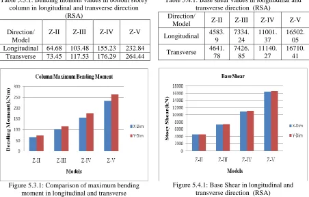
[image:3.595.66.293.314.491.2]127 Table 5.3.1: Bending moment values in bottom storey
column in longitudinal and transverse direction (RSA)
Direction/ Model
Z-II Z-III Z-IV Z-V
Longitudinal 64.68 103.48 155.23 232.84 Transverse 73.45 117.53 176.29 264.44
Figure 5.3.1: Comparison of maximum bending moment in longitudinal and transverse
direction (RSA)
Bending moment is one of the important parameter for designing of any structure. For comparison purpose here bending moment of bottom storey is considered. It is seen that there is increment in bending moment in bottom storey columns in longitudinal as well as transverse direction for increasing in seismic zones from II to V. For model II (EQZ-III) increment in bending moment is up to 60% as compared with model I(EQZ-II) in both longitudinal and transverse direction. For model III (EQZ-IV) increment in bending moment is up to 140% as compared with model I(EQZ-II) in both longitudinal and transverse direction. For model IV (EQZ-V) increment in bending moment is up to 260% as compared with model I(EQZ-II) in both longitudinal and transverse direction. Also it is observed that from zone II to zone III this increment is 60% whereas from zone III to zone IV and from zone IV to zone V it is 50%.
5.4 Base Shear
[image:4.595.73.525.105.393.2]A graph is plotted between different building models and the base shear as shown in figure 5.4.1. The Base shear values in longitudinal and transverse direction are given in table 5.4.1.
Table 5.4.1: Base shear values in longitudinal and transverse direction (RSA)
Direction/
Model Z-II Z-III Z-IV Z-V
Longitudinal 4583. 9
7334. 24
11001. 37
16502. 05
Transverse 4641. 78
7426. 85
11140. 27
16710. 41
Figure 5.4.1: Base Shear in longitudinal and transverse direction (RSA)
It is seen that there is increment in base shear in longitudinal as well as transverse direction for increasing in seismic zones from II to V. For model II (EQZ-III) increment in base shear is up to 60% as compared with model I (EQZ-II) in both longitudinal and transverse direction. For model III (EQZ-IV) increment in base shear is up to 140% as compared with model I (EQZ-II) in both longitudinal and transverse direction. For model IV (EQZ-V) increment in base shear is up to 260% as compared with model I (EQZ-II) in both longitudinal and transverse direction. Also it is observed that from zone II to zone III this increment is 60% whereas from zone III to zone IV and from zone IV to zone V it is 50%.
5.5 Storey Shear
128 Table 5.5.1: storey shear values in longitudinal
direction (RSA) Storey
/Model Z-II Z-III Z-IV Z-V
5
1003.7 3
1605.9
7 2408.96 3613.43
4
2270.6 1
3632.9
7 5449.46 8174.19
3
3120.2 5
4992.3
9 7488.59
11232.8 9
2
3742.2 2
5987.5
5 8981.33
13471.9 9
1
4204.5 1
6727.2 2
10090.8 2
[image:5.595.69.293.285.572.2]15136.2 3
Table 5.5.2: storey shear values in transverse direction (RSA)
Storey/
Model Z-II Z-III Z-IV Z-V 5 1266.37 2026.19 3039.28 4558.92 4 2452.21 3923.53 5885.3 8827.94
3 3209.01 5134.41 7701.62
11552.4 2
2 3859.28 6174.85 9262.28
13893.4 2 1 4316.22 6905.96 10358.93 15538.4
[image:5.595.73.291.595.741.2]Figure 5.5.1: Storey Shear in longitudinal direction
Figure 5.5.2: Storey Shear in transverse direction (RSA)
It is seen that there is increment in storey shear in longitudinal as well as transverse direction for increasing in seismic zones from II to V. For model II (EQZ-III) increment in storey shear is up to 60% as compared with model I(EQZ-II) in both longitudinal and transverse direction. For model III (EQZ-IV) increment in storey shear is up to 140% as compared with model I(EQZ-II) in both longitudinal and transverse direction. For model IV (EQZ-V) increment in storey shear is up to 260% as compared with model I(EQZ-II) in both longitudinal and transverse direction. Also it is observed that from zone II to zone III this increment is 60% whereas from zone III to zone IV and from zone IV to zone V it is 50%.
5.6 COMPARISON OF ANALYSIS RESULTS FOR ALL ZONES & THEIR CONCLUSIONS
The analysis results of all the building models are compared for all zones II, III, IV and V. The observations are as follows
• It is observed that mostly all the comparisons parameters are increase 0.6 times, 1.4 times and 2.6 times for zone III, zone IV and zone V respectively.
• The bending moments are also increased to 260% in zone V as compared to zone II.
• The storey shear and base shear are also increased to 260% in zone V as compared to zone II.
• There is no change fundamental time period of structure in first mode.
REFERENCE
[1] Sonia Longjam, S. Aravindan: “Analysis and design of shopping mall against lateral forces” (International journal of engineering science invention ISSN online: 2319-6734, ISSN print: 2319-6729)