---
---
- - - - -- - - --
----- ----
-
---
___
0
-SC34-0124-0
S1-21
PROGRAM PRODUCT
IBM Series/1
Program Preparation Subsystem
M aero Assembler
User's Guide
Program Number 5719-AS1
rFD::===:e==:
;;cq:=r:1oT'
...
II
11111111111111111111111111111111111111111111111
o [])
111111111111111111111111111111111111111111111111
o
[]j
0 [])1111111111111111111
~
o
[{])I
111111111111111111111111111111111111111111111111
V
~((b
---
---
- ----
- ---
-
-
----
-
-
---
---
--_.-c
o
SC34-0124-0
Sl-21
IBM Series/1
PROGRAM PRODUCT
Program Preparation Subsystem
Macro Assembler
User's Guide
Program Number 5719-ASl
This publication is for planning purposes only. The infonnation herein is subject to change before the products described become available.
First Edition (February 1977)
This manual applys to the IBM Series/l Program Preparation Subsystem, program number 5719-ASl.
Significant changes or additions to the contents of this publication will be reported in subsequent revisions or Technical Newsletters. Requests for copies of IBM publications should be made to your IBM representative or the IBM branch office serving your locality.
A form for readers' comments is provided at the back of this pUblication. If the form has been removed, send your comments to IBM Corporation, Systems Publications, Department 27T, P.O. Box 1328, Boca Raton, Florida 33432. Comments become the property of IBM.
© Copyright International Business Machines Corporation 1977
ii SC34-0124
o
c
c
o
Preface v
Introduction 1-1
Coding and Structure of the Assembler Language 2-1
Functional Characteristics 3-1
Machine Instructions 4-1
Assembler Instructions 5-1
Macro Language 6-1
Using the Macro Assembler 7-1
Appendix A. Structured Programming Macros A-I
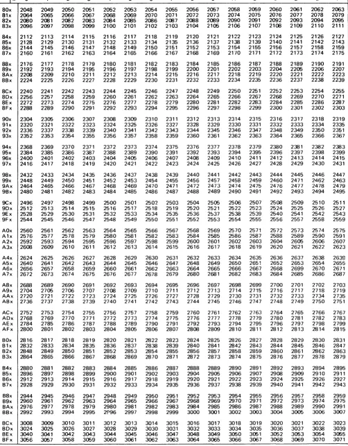
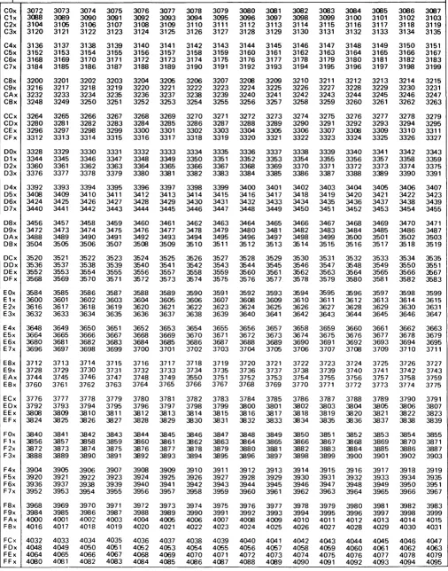
Appendix B. Decimal/Binary/Hexadecimal Conversions 8-1
Appendix C. American National Standard Code for Information Interchange (ASCII) C-1
Appendix D. Perforated Tape Transmission Code/Extended Binary Coded Decimal (PTTC/EBCD) D-l
Appendix E. Priority List for Assembler Instructions £-1
Appendix F. Summary of Constants F-l
Appendix G. Macro Language Summary G-l
Appendix H. Assembler Language Summary H-l
Appendix J. Macro Language Instruction Summary J-l
Index X-I
iv SC34-0124
o
(
\;.,
,
(
c
Preface
What This Manual Can
Do
For You
This publication is a reference for programmers who use the IBM Series/l
assembler language. It gives specific information about assembler language
functions and coding specifications.
How TIt;s
Mall.al
Is
Orgall;zed
• Chapter 1 gives a brief introduction to the assembler and its features.
• Chapter 2 discusses the structure of the assembler language. It also explains
the coding rules you must follow in coding an assembler-language program. • Chapter 3 describes the characteristics of the IBM Series/l processor. It
explains register usage, addressing modes, and other information you should understand to effectively use the assembler.
• Chapter 4 describes the machine instructions. It explains the function of each
instruction and how to code it. For most instructions, this chapter gives examples to help you better understand how the instructions work.
• Chapter 5 describes the assembler instructions. It explains what they do and
how to code them, then gives examples of their use.
• Chapter 6 describes the macro language. Programming in macro language simplifies coding, reduces the chance for making errors, and ensures that standard sequences of instructions are coded.
• Chapter 7 describes assembler options, the program listing produced by the
assembler and the control statements necessary to run and assembly. It also
includes performance, invoking of the assembler, and object module formats. • The appendixes cover structured macros, conversion tables, a priority list for assembler instructions, a summary of constants, and a summary of the macro language.
Each chapter of this publication is a separate module. This organization allows you to use the chapters as published or to combine them with information from other sources.
Each chapter has a detailed table of contents. A master index is included at the end of the manual.
Wltat Yo. SIIo.ld
KilO",Before Yo" Beg;"
Related Publications
You should be familiar with the concepts of modular programming, and you should be experienced in assembler-language coding.
The following publications may be helpful to you. The manuals not available at this time do not show an order number and are noted by an asterisk.
IBM Series/l Program Preparation Subsystem: Introduction, GC34-0121
IBM Series/l Program Preparation Subsystem: Batch User's Guide
*
IBM Series/l Program Preparation Subsystem: Text Editor User's Guide
*
IBM Series/l Program Preparation Subsystem: Application Builder User's Guide
*
IBM Series/l Model 3: 4953 Processor and Processor Features Description,
vi SC34-0124
IBM Series/l Model 5: 4955 Processor and Processor Features Description,
GA34-0021
IBM Series/l Realtime Programming System: Macro User's Guide-Supervisor
*
~IBM Series/l Realtime Programming System: Macro User's Guide-Data , J
Management
*
(
c
Section Contents
The Assembler Language 1-3 Machine Instructions 1-3 Assembler Instructions 1-3 Macro Instructions 1-3 The Assembler Program 1-3 Coding Aids 1-5
Symbolic Representation of Program Elements 1-5 Variety of Data Representation 1-3
Relocatability 1-5
Addresses and Addressing 1-5 Register Usage 1-5
Segmenting a Program 1-6
Linkage Between So urce Modules 1-7 Program Listing 1-7
Programmer Procedures 1-7
Step 1. Design Application and Support System 1-7 Step 2. Generate Realtime Operating System 1-8 Step 3. Generate Batch Processing and Program
Preparation Facility 1-8
Step 4. Code Assembler Language Programs 1-8 Step 5. Create Source Modules 1-10
Step 6. Create Object Modules 1-10 Step 7. Create Composite Modules 1-10 Step 8. Create Task Sets 1-10
Step 9. Install Task Sets 1-10 Step 10. Execute Task Sets 1-10 Step 11. Debug Task Sets 1-10 Summary of Programmer Proced ures 1-10
(
c
(
C
= ==The Assembler Language
Maclti1le [IIStnlCtiOIlS
Assembler [atnlctio1ls
Macro [IIStnlCtiOIlS
The Assembler
Program
Assembler language is a symbolic programming language that resembles machine language in form and content. It is made up of statements that represent
instructions and comments. The instruction statements are the working part of the language and are divided into three groups:
• Machine instructions • Assembler instructions • Macro instructions
A machine instruction is the symbolic representation of a hardware instruction in the Series/l instruction set. Machine instructions are described in Chapter 4 of this manual.
An assembler instruction is a request to the assembler program to perform certain operations during the assembly of a source module; for example, defining data constants, defining the end of the source module, and reserving storage areas. Except for the instructions that define constants, parameter lists, or provide boundary alignment, the assembler does not translate assembler
instructions into object code. The assembler instructions are described in Chapter 5 of this manual.
A macro instruction is a request to the assembler program to process a
predefined sequence of code called a macro definition. From this definition, the assembler generates machine and assembler instructions which it then processes as if they were part of the original input in the source module.
You can prepare macro definitions, then call them by coding the corresponding macro instructions. A complete description of the macro language, including the macro definition, the macro instruction, and the conditional assembly language is given in Chapter 6 of this manual.
The assembler program, also referred to as the assembler, processes the machine, assembler, and macro instructions you have coded in the assembler language and produces an object module in machine language.
1 - 4 SC34-0124
Coding
Assembly
Applica tion build
Execution
Application builder
System
Programmer
Assembler
The assembler processes instructions at two distinct times. It processes macro instructions at preassembly time, and it processes machine instructions and assembler instructions at assembly time.
The assembler also- produces information for other programs. The application builder uses such information to combine object modules and task sets which can be executed.
(~"'
\J
c
Coding Aids
It is normally difficult to write an assembler language program using only
machine instructions. The assembler provides some coding aids that make this task easier. They are summarized next.
Symbolic
R~prese,.tatio,.of Program Elements
Symbols greatly reduce programming effort and errors. You can define symbols to represent storage addresses, displacements, constants, registers, and other elements that make up the assembler language. These elements include operands, operand subfields, terms, and expressions. Symbols are easier to remember and code than numbers; also, they are listed in a symbolic cross-reference table which is printed in the program listing. Thus, you can easily find a symbol when
searching for an error in your code.
Variety of Data Represe"tation
Relocatability
Addresses a"d Addressi"g
Register Usage
You can use decimal, binary, hexadecimal, ASCII or EBCDIC character
representation, which the assembler converts for you into the binary equivalents required by the machine instructions.
The assembler produces an object module that can be relocated from the originally assigned storage area to any other suitable main storage area without affecting program execution. The application builder does the relocation.
Each byte in main storage is specified by a unique numeric address. When you write a program, you are essentially telling the computer what addresses are involved in the operation you want it to perform. You are usually not concerned with the specific main storage locations, because the assembler keeps track of the location of the statement in your program (relative to the beginning of your program). The assembler assigns the proper address to each assembled machine-language instruction.
To keep track of the locations, the assembler uses a location counter. The counter is set to zero at the beginning of an assembly unless your program specifies otherwise. The counter is then increased by the number of bytes of main storage that each instruction needs. In this way, each statement is assigned an address relative to the beginning of the program. The assembler can then assign the addresses and displacements that are required when it produces the object program. (A displacement is the difference between the counter value of one statement and that of another.)
When your program is processed by the application builder and loaded, each statement for which storage is allocated takes on a relocated address, which is
equal to the beginning main-storage address of the program plus the location
counter value for that instruction (based on a beginning location counter value of zero).
To locate data, most machine instructions refer to a storage address. The Series/1 uses a variety of methods (called addressing modes) to find the data you request in your machine instructions. Addressing modes are described in Chapter 3; how you use them is discussed in Chapter 4.
Anyone of the eight general-purpose registers can be used to hold a value, an address, or a displacement for manipulating data, maintaining counters, or determining the address of a particular instruction or storage location.
Segmelltillg a Program
1 - 6 SC34-0124
be executed unless a branch or jump instruction breaks the normal sequence. When this occurs, the contents of the instruction address register change because the program transfers control to an instruction not immediately following the current instruction.
You can code a program in sections and later combine the sections into the executable program. Sections are assembled in any combination, individually or grouped. You arrange the sections in the order required for proper execution of the program during the combining process. The combining process is called
linking and is performed by the application builder program.
Dividing a large program into several sections and assemblies has certain advantages:
• More than one programmer can code sections of the program. Each can assemble and debug his sections independently of the others.
• The linking process is much faster, in terms of computer time, than the assembly process. You can assemble a section of the program and link the new section to the already assembled program. This uses less computer time than assembling the entire program.
• Sections that are common to more than one program are assembled only once. You can then link the common sections to the unique sections of each
program. You again reduce computer time and also have shorter assembly listings that are easier to debug.
• You can configure a program to various main storage requirements much more easily by linking the sections into different combinations of storage loads or phases. Of course, you must make provisions for these variations in your program logic.
Four types of program sections can be defined in the assembler
language--control sections, common sections, global sections, and dummy sections. Control sections define the object code, that is, machine instructions and data definitions. A common section defines an area of main storage that can be shared with the program sections in multiple assemblies within a task. A global section may define either task set or system global area. Task set global is addressable by all programs executing in a partition. If a task set issues a request to transfer control to another task set, the portion of task set global common to both task sets is not overlayed. System global is contained in the shared task set and is addressable by all programs link-edited against the shared task set. The application builder determines whether a global section is a task set or system global, according to the name associated with the global section. If the named global exists in the shared task set and has the proper attributes (for example, length), the shared task set global area will be used, otherwise, a global area will be generated within the task set. For more information on task sets, reference the Application Builder User's Guide. A dummy section describes to the assembler the format of data located elsewhere. Dummy sections do not appear in the output module of an assembly. The linking process combines only control, common and global sections.
The following assembler instructions define the beginning and end of the various sections in your assembly.
• START and CSECT instructions define the beginning of a control section. START is used only to define the first control section in an assembly. • The COM instruction defines the beginning of a common section. • The GLOBL instruction defines the beginning of a global section. • The DSECT instruction defines the beginning of a dummy section.
• The end of any type of section is defined when another section is started. The END instruction defines the end of all sections in an assembly.
(
,
(
c
Liltkage Betweell SOflrce
MOIbIies
Program Listillg
Programmer Procedures
You can create symbolic linkages between separately assembled source modules. This allows you to refer symbolically from one source module to data defined in another source module. You can also use symbolic addresses to branch between modules.
Combining separately assembled control sections successfully depends on the techniques for symbolic linkages between the control sections. For example, symbols can be defined in one module and referred to in another. The
application builder then completes the linkage, using the information passed to it by the assembler. Not only is the linkage symbol defined (used as a name), it must also be identified to the assembler by means of an ENTRY assembler instruction unless the symbol is the name of a CSECT or START statement. After a symbol is identified as one that names an entry point, another module can then use that symbol to bring about a branch operation or a data reference.
A module that refers to a linkage symbol defined in another module must identify it as an externally defined symbol used to bring about linkage. The EXTRN or WXTRN assembler instructions identify such symbols.
Symbolic linkage can also be achieved by means of the V-type or W-type address constant, or by means of the BALX or BX machine instruction. Each constant is an external reference since it is created from an externally defined symbol that need not be identified by an EXTRN or WXTRN statement. The V-type or W-type address constant can be used to branch to other modules or to refer to data in those modules.
The assembler produces a listing of your source module, including any generated statements, and the object code assembled from the source module. You can control the content of the listing to a certain extent. The assembler also prints messages about actual errors and warnings about potential errors in your source module. A complete description of the program listing is given in Chapter 7 of this manual.
This book gives you information on the assembler language and on the execution of the assembler. Using Series/l involves much more. This section gives you an outline of the process required to generate and execute a program. A step by step procedure, which refers to the flowchart on page 1-7, points you to the library source containing more information.
Step
1. Desigll Applicatioll altd S"pport System
You must combine your knowledge of designing a realtime system with the Series/Ito produce a specification furnishing information for all succeeding steps.
An introduction to the Series/l programming support and references to detailed information is in the IBM Series/l Realtime Programming System:
Step
2. Gellerate Ilealtillle
~rati",System
You can generate your specific operating system by using information in the
IBM Series/l Realtime Programming System: Generation and Installation
Procedures
*.
Step
3. Generate lJatc" Processi"g au Program PrePllratio1l Facility
You can generate your specific system by using information in the IBM Series/l
Program Preparation Subsystem: Batch User's Guide
*.
Step
4. Code Asselllbler lA""",ge Programs
1 - 8 SC34-0124
This book contains information on the coding of all assembler language statements and on structured macros furnished as a part of the assembler. You may also need to code macro statements for macros defined specifically for your application and code system support macros furnished as a part of that program product.
Information on these macros is in three volumes: IBM Series/l Realtime
Programming System: Macro User's Guide-Supervisor *; IBM Series/l
Realtime Programming System: Macro User's Guide-Data Management *;
IBM Series/l Realtime Programming System: Macro User's
(
Series/1
and
Application
System
Facilities
Code Routines
Create Source Modules
Create Object Modules
Create Composite
Modules
Create Task: Set
Install Task Set
Step
5. Create SO.Fee Mod.les
State any special requirements for source modules in your application
specification. Information on normal requirements for source modules assembled
by the Series/1 macro assembler is in this book and in the IBM Series/l ( "\
Program Preparation Subsystem: Text Editor User's Guide
*
\. )
Step 6. Create Object Mod.les
State any special requirements for object modules in your application
specification. Information on normal requirements for object modules processed by the Series/1 application builder is in this book.
Step 7. Create COMposite Modllies
Step
8.
Create Task Sets
Step
9.
Illstall Task Sets
Step 10. Execllte Task Sets
Step
11.
Deb", Task Sets
State any special requirements for composite modules in your application
specification. Requirements for composite modules which are used in building task sets
to be executed under Series/1 realtime operating system are in the IBM Series/l
Program Preparation Subsystem: Application Builder User's Guide
*.
State the requirements for task sets in your application specification. Information on using the application builder to meet these requirements is in the IBM
Series/l Program Preparation Subsystem: Application Builder User's Guide
*
State any requirements for installation of task sets in your application specification. Information on how to meet these requirements is in the IBM
Series/l Realtime Programming System: Macro User's Guide-Supervisor *.
State requirements for executing your application task sets in your application specification. Information to help you meet these requirements is in the IBM
Series/l Realtime Programming System: Operator Commands and Utilities
*
andIBM Series/l Program Preparation Subsystem: Batch User's Guide
*
To debug task sets reference one of the following manuals depending on your specific problem. The IBM Series/l Realtime Programming System: Control
Blocks and Debugging Guide *, gives you error log descriptions, and explains
how to get a storage dump. Information on macro errors is found in the IBM
Series/l Realtime Programming System Macro Reference
*.
For descriptions ofcontrol blocks reference the Program Logic Manual (PLM) for your particular function. Explanations for messages and codes are found in the IBM Series/l
Program Preparation Subsystem: Messages and Codes
*
manual and/or IBMSeries/l Realtime Programming System: Messages and Codes
*
*
These books are not presently available.Sllmmary of Programmer Procedllres
t - to SC34-0124
The table below gives a summary of the procedures to tie them to processes or publications in Series/1. For a detailed overview of Series/1 and a comparison of how system functions are supported by different languages, refer to the IBM
Series/l Realtime Programming System: Introduction and Planning Guide,
Programmer Procedure Associated System Step Publication
1. Planning and System None. IBM Series/ J Realtime
c
Design Programming System:Introduction and Planning Guide, GC34-0102
2. Building the Realtime System Generation IBM Series/ J Realtime Building the Realtime Programming System:
Operating System Generation and
Installation Procedures
*
3. Building the Program System Generation IBM Series/ J ProgramPreparation & Batch Preparation Subsystem:
Processing System Batch User's Guide
*
4. Programs None. (Coding sheet) IBM Series / J Program Preparation Subsystem: Macro Assembler User's Guide, SC34-0124 IBM Series/ J Realtime Programming System: Macro User's Guide-Supervisor
*
IBM Series/ J Realtime Programming System: Macro User's Guide-Data Management*
IBM Series/ J Realtime Programming System: Macro User's
Guide-Communications
*
IBM Series/ J Realtime Programming System: Macro Reference*
5. Creating Source Modules Text Editor (Note. Or, use IBM Series/ J Program(On diskette) 3741) Preparation Subsystem: Text Editor's User's Guide
*
6. Creating Object Modules Assembler IBM Series / J Program Preparation Subsystem: Macro Assembler User's Guide, SC34-0124
7. Creating Composite Modules Application Build IBM Series/I Program Preparation Subsystem: Application Builder User's Guide
*
8. Building Task Sets Application Build: Phases I IBM Series/ J Program &2&3 Preparation Subsystem:
Application Builder User's Guide
*
9. Installing Task Sets (Not A series of steps using the IBM Series/l Realtime required) utility DEFINE and COpy Programming System:
10. Executing Task Sets Direct: STARTTASK operator command or supervisor macro
Batch: Job Stream Processor
11. Debugging Task Sets Error Management
Messages and Return Codes
*These books are not presently available.
1 - 12 SC34-0124
IBM Series/I Realtime Programming System: Operator Commands and Utilities
*
IBM Series/I Realtime Programming System: Macro User's Guide-Supervisor
*
IBM Series/I Program Preparation Subsystem: Batch User's Guide*
IBM Series/! Realtime Programming System: Control Blocks and Debugging Guide*
IBM Series/! Program Preparation Subsystem: Messages and Codes*
andIBM Series/! Realtime Programming System: Messages and Codes
*
("\
"
)
(
c
Chapter 2. Coding and Structure of the Assembler Language
Section Contents
Coding Conventions 2-3 Field Boundaries 2-3 The Statement Field 24
The Continuation Indicator Field 24 The Identification and Sequence Field 24 Field Positions 24
Continuation Lines 2-5
Comments Statement Format 2-5 Instruction Statement Format 2-5 Assembler Language Structure 2-7
Character Set 2-7 Terms 2-8 Symbols 2-8
The Symbol Table 2-8 Restrictions on Symbols 2-9
Location Counter Reference 2-11
Symbol Length Attribute Reference 2-12 Other Attribute References 2-14
Self-defining Terms 2-15 Expressions 2-17
Absolute Expressions 2-17 Register Expressions 2-18 Relocatable Expressions 2-19
c
c
Coding Conventions
IBl1
This chapter describes the coding conventions that you must follow in writing assembler language programs. Assembler language statements are usually written on a coding form before they are entered as source statements through some form of input to the system. You can write assembler language statements on the standard coding form (GX28-6509). Columns 1-72 of this form correspond to the positions on a source statement entered at the operator station.
IBM Sy.t.ml360 A ••• mbl.r Coding Form GX2U609-6U1MO&O-PnnlMl rn U.s.A.
PUNCHING I GRAPHIC I I I I I I I I PAGE OF 1 - - - I . . - o - A T E - - - 1 I N S T R U C T I O N S I I I I I I I I I CARD ELECTRO NUMBER
8 10 Oper.llon Operlild 25
• A If¥ldllrri clll'd form, IBM "lKrro 6509, If .... tlll.Jble for punchmg 1Of."~ Itllnrm6f'ltr from dll' 'orm Inttrvcr,ofll forvlmg thiS form .,,,m IflY IBM Sysnrml360_mbl"rl6figu.", m"'~m.,u •. Add,., commenD crNlCflm/flg thIS form fa IBM Nord" LMJofltury, Publiclltion, o-lopmtIf,t,
801C 962,S 181 09Lldmgo9,Swedt1n.
'NCOf lormiper padm..,. ~I'V JI,g,lly
Field Bo",.daries
Assembler language statements usually occupy one 80-column line on the standard form. (For statements occupying more than 80 columns, see
"Continuation Lines" in this chapter.) Note that any printable character entered at a position in a source statement is reproduced in the listing printed by the assembler. Each line of the coding form is divided into three main fields: • The statement field
De
Statemellt Field
LABEL
\
Begincolumn'
The instructions and comments statements must be written in the statement field. The statement field starts in the "begin" column and ends in the "end" column.
Any continuation lines needed must start in the "continue" column and may
0.
Ji
extend to the "end" column. The assembler assumes the following standard " values for these columns:• The "begin" column is column 1 • The "end" column is column 71 • The "continue" column is column 16.
These standard values can be changed by using the ICTL instruction. However, all references to the "begin", "end", and "continue" columns in this manual refer to the standard values previously described.
OPCOD OPERANDS
CONTINUATION
\
Continuecolumn I
Statement field
REt1ARKS
LINES MUST START IN COLUMN
16
Continuation indicator field
':>.
'",
XEnd
/
columnTIle COlftb"UltiOlf Ilfdicator Fkld
The continuation indicator field occupies the column following the end column. Therefore, the standard position for this field is column 72. A nonblank character
in this column indicates that the current statement is continued on the next line. t ';
This column must be blank if a statement is completed on the same line; \. otherwise the assembler will treat the statement that follows on the next line as a
continuation line of the current statement.
TIle Idelfti/icatiolf alfd Seq"ellce Fkld
Fieltl Positiolls
2 - 4 SC34-0124
The identification and sequence field can contain identification characters, or sequence numbers, or both. If you have coded the ISEQ instruction, the assembler will verify whether or not the source statements are in the correct sequence.
Note. The ISEQ instruction is used to define the identification and sequence field column boundaries (there are no 'standard' assembler default boundaries for this field). However, column 73 through 80 are set aside for this purpose on the standard coding form, and so are normally used. The single requirement is that this field must not be specified to be within the statement field boundaries.
The statement field is always coded between the begin and the end columns. The continuation indicator field is always coded in the column after the end column. The identification and sequence field usually is the field after the continuation indicator field. However, the ICTL instruction, by changing the standard begin, end, and continue columns can create a field before the begin column. This field can then contain the identification and sequence field.
c
c
Contin"ation Lilies
To continue a statement on another line:
1. Enter a nonblank character in the continuation indicator field (column 72). This character is not treated as part of the statement coding. An operand field can be continued by coding it up through column 71, or by terminating it with a comma followed by at least one blank.
2. Continue the statement on the next line, starting in the continue column (column 16). The columns prior to the continue column (columns 1-15)
must be blank.
Only one continuation line is allowed for a single assembler language
statement. However, macro instruction statements and the prototype statement of macro definitions can have as many continuation lines as needed. When more than one continuation line is needed, enter a nonblank character in the continuation indicator field of each line that is to be continued.
Comments Statement F017lUlt
Comments statements are not assembled as part of the object module, but C!re only printed on the assembly listing. You can write as many comments statements as you need, as long as you follow these rules:
• Comments statements require an asterisk in the begin column.
Note. Internal macro definition comments statements require a period in the
begin column, followed by an asterisk in the next column (for details see "Internal Macro Comments Statements" in this chapter).
• You can use any characters, including blanks and special characters, of the character set.
• Comments statements cannot be continued. Code comments statements in the statement field and do not let them run over into the continuation indicator field.
• Comments statements must not appear between an instruction statement and its continuation lines.
IlIStnlction Statelllellt F017lUlt
LABEL
SECTDEF
The statement field of an instruction statement must include an operation entry and can contain one or more of the following entries:
• A name entry • An operand entry • A remarks entry
The standard coding form is divided into fields that provide fixed positions for the name, operation, and operand entries.
1. An 8-character name field starting in column 1 2. A 5-character operation field starting in column 10 3. An operand field that begins in column 16
HVW
BAL
CSECT
ORG
R3,ADCON
ADDRESS,R7
NAME ENTRY OMITTED
REMARKS ENTRY
OPERAND ENTRY NOT REQUIRED
OPERAND ENTRY OMITTED
LABEL
MVW
It is not necessary to code the operation and operand entries according to the fixed fields on the standard coding form. Instead, you can write these entries in any position, called free format, subject to certain formatting specifications.
Whether you use fixed or free format, the following general rules apply when ,.--)
you code an instruction statement: \.
J
• Write the entries in the following order: name, operation, operand, and remarks.
• The entries must be contained in the begin column (1) through the end column (71) of the first line and, if needed, in the continue column (16) through the end column (71) of any continuation lines.
• The entries must be separated from each other by one or more blanks.
• If used, the name entry must start in the begin column (normally column 1). • The name and operation entries, each followed by at least one blank, must be
in the first line of an instruction statement.
• The operation entry must start to the right of the begin column.
R3,ADCON
FIXED FORMAT STATEMENT.
LABEL MVW R3,ADCON FREE FORHAT STATEMENT.
LABEL
HVW
XR3,ADCON ONLY OPERANDS AND REMARKS ALLOWED
HERE.-HVW R3,ADCON NAME ENTRY OMITTED, COLUMN 1 MUST BE BLANK.
LABEL
MVW
2 - 6 SC34-0124
R3,
ADCON
CONTINUE OPERANDS
ON NEXT LINE
X
The name entry identifies an instruction statement. The following rules apply to the name entry:
• It is usually optional.
• It must be a valid symbol of 1-8 characters at assembly time (after substitution for variable symbols, if specified on model statements within macro definitions).
The operation entry is the symbolic operation code that specifies the machine, assembler, or macro instruction to be processed. The following rules apply to the operation entry:
• It is mandatory.
• For machine and assembler instructions it must be a valid symbol at assembly time (after substitution for variable symbols, if specified on model statements within macro definitions). The standard symbolic operation codes are 5 characters or less.
• For macro instructions it can be any valid symbol of 1-8 characters that is not identical to the operation codes for machine and assembler instructions. The operand entry has one or more operands that identify and describe the data used by an instruction. The following rules apply to operands:
• One or more operands are usually required, depending on the instruction. • Operands must be separated by commas. No blanks are allowed between the
c
c
continued on the next line, the last operand on the first line can be terminated with a comma followed by one or more blanks.
• Operands must not contain embedded blanks, because a blank normally indicates the end of the operand entry. However, blanks are allowed if they are included in character strings enclosed in apostrophes (for example, C' IN') or in logical expressions (see "Logical (SETB) Expressions" in Chapter 6).
You can use a remarks entry to comment on the current instruction. The
following rules apply to the remarks entry:
• It is optional.
*
These manuals not presently available.• It can contain any of the 256 characters of the character set, including blanks and special characters.
• It can follow any operand entry.
• If an entire operand entry is omitted, remarks are allowed if the absence of the operand entry is indicated by a comma preceded and followed by one or more blanks.
Note. Macro prototype statements and macro instructions without operands
cannot have a remarks entry, even if a comma is coded as described above.
Assembler Language Structure
Cltaracter Set
This section describes the structure of the assembler language (the various statements allowed in the language and the elements that make up those statements) .
A source module is a sequence of instruction and comment statements that
make up the input to the assembler. There are 3 types of instruction statements:
• Machine instructions-symbolic representation of machine language
instructions, which the assembler translates into machine language code
• Assembler instructions-instructions to the assembler program to perform
certain operations during assembly of a source module, such as defining data constants and reserving storage areas
• Macro instructions-instructions to the assembler program to process
predefined sequences of code called macro definitions (from which the
assembler generates machine and assembler instructions which it then processes as if they were part of the original input source module)
The operand field of machine instructions is composed of expressions, which
are composed of terms and combinations of terms. Remarks on the instruction
statements and comments statements are composed of character strings. Terms
and character strings are both composed of characters. The following paragraphs define these language elements.
Terms, expressions, and character strings used to build source statements are written with the following characters:
• Alphameric characters
Alphabetic characters A through Z
- Special characters $, #, and @
- Digits 0 through 9
• Special characters
+ - , = .
* ( ) , /
& blank Note.set.
Terms
Symbols
The S)'IIIbol Table
2 - 8 SC34-0124
Normally, strings of alphameric characters are used to represent data, and special characters are used as:
• Arithmetic operators in expressions • Data or field delimiters
• Indicators to the assembler for specific handling
A term is the smallest element of the assembler language that represents a distinct and separate value. It can therefore be used alone or in combination with other terms to form expressions. Terms have absolute or relocatable values that are assigned by the assembler or are inherent in the terms themselves.
A term is absolute if its value does not change upon program relocation and is
relocatable if its value can be modified to compensate for a change in program
origin.
The types of terms are:
• Symbols-absolute or relocatable; value is assigned by the assembler
• Location counter reference-relocatable; value is assigned by the assembler
• Symbolic parameter attributes-absolute; value is assigned by the assembler
• Self-defining terms-absolute; value is inherent in term
You can use a symbol to represent storage locations or arbitrary values. You can write a symbol in the name field of an instruction and and then specify this symbol in the operands of other instructions, thus referring to the former instruction symbolically. This symbol represents a relocatable address.
You can also assign an absolute value to a symbol by coding it in the name field of an EQU or EQUR instruction with an operand whose value is absolute. Symbols in the name field of EQUR instructions can be used in other instruction operands to represent registers; symbols in the name field of EQU instructions can be used in other instruction operands as displacements in explicit addresses, immediate data, lengths, and implicit addresses with absolute values. The advantages of symbolic numeric representation are:
• You can remember symbols more easily than numeric values, thus reducing programming errors and increasing programming efficiency.
• You can use meaningful symbols to describe the program elements they represent; for example, INPUT can name a field that is to contain input data, or INDEX can name a register to be used for indexing.
• You can change the value of one symbol (through an EQU instruction) more easily than you can change several numeric values in many instructions. • Symbols are entered into a cross-reference table that the assembler optionally
prints in the program listing.
The symbol cross-reference table helps you to find a symbol in a program listing, because it lists (1) the number of the statement in which the symbol is defined (that is, used as the name entry), and (2) the numbers of all the statements in which the symbol is used in the operands.
The assembler maintains an internal table called a symbol table. When the assembler processes your source statements for the first time, the assembler assigns an absolute or relocatable value to every symbol that appears in the name field of an instruction. The assembler enters this value, which normally reflects the setting of the location counter, into the symbol table; it also enters the attributes with the data represented by the symbol. The values of the symbol and
( '
c
c
Restrictiolls
OilSymbols
Predefmed Register Symbols
its attributes are available later when the assembler finds this symbol used as a term in an operand or expression.
The assembler recognizes three types of symbols:
• Ordinary symbols-used in the name and operand fields of machine and
assembler instruction statements; written as an alphabetic character followed by 0-7 alphameric characters (no blanks allowed). For example: BEGIN
• Variable symbols-used only in macro processing conditional assembly
instructions; written as an ampersand followed by an alphabetic character followed by 0-6 alphameric characters (no blanks allowed). For example:
&PARAM
• Sequence symbols-used only in macro processing conditional assembly
instructions; written as a period followed by an alphabetic character followed by 0-6 alphameric characters. For example: .SEQOl
An ordinary symbol is considered defined when it appears as:
• The name entry in a machine or assembler instruction of the assembler language, or
• One of the operands of the following instructions: EXTRN, WXTRN.
Ordinary symbols that appear in instructions generated from model statements at preassembly time are also considered defined.
The assembler assigns a value to the ordinary symbol in the name field as follows.
• According to the address of the leftmost byte of the storage area that contains one of the following:
Any machine instruction
- A storage area defined by the DS instruction
- Any constant defined by the DC instruction
The address value thus assigned is relocatable, because the object code assembled from these items is relocatable.
• According to the value of the expression specified in the operand of an EQU instruction. This expression can have a relocatable or absolute value, which is then assigned to the ordinary symbol.
• According to the value of the expression specified in the operand of an EQUR
instruction. This expression must have an absolute value in the range 0-7,
which is then assigned to the register symbol.
The value of an ordinary symbol must be representable in 16 bits.
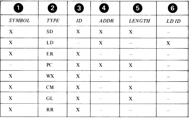
Note. The symbol table can contain a maximum of 57330 entires. In a single
assembly, the total number of ordinary symbol entries plus ESD entries cannot exceed this maximum. ESD entries are created for:
• control sections • dummy sections • global sections • common sections
• unique symbols in EXTRN, WXTRN, and ENTRY statements • V, W, and N-type address constants
• BALX and BX instructions.
The following symbols are predefined by the assembler and reserved for use only as register symbols:
Unique Definition
2 - 10 SC34-0t24
• R3 (general-purpose register 3) • R4 (general-purpose register 4) • R5 (general-purpose register 5) • R6 (general-purpose register 6) • R7 (general-purpose register 7) • FRO (floating-point register 0) • FRI (floating-point register 1)
• FR2 (floating-point register 2) • FR3 (floating-point register 3)
These symbols are absolute and used only for register reference in machine and assembler instruction operands. Any other usage causes an error message to be generated. Predefined register symbols appear in the cross-reference listing.
A symbol must be defined only once in a source module (even a source module that contains two or more control sections) with the following exceptions: • You can use a duplicate symbol as the name entry of a CSECT, GLOBL,
COM or DSECT instruction. The first use identifies the beginning of the control section, and subsequent uses identify continuations of the control section. A symbol used in the name field of one type of section may not be repeated on another type. For example, a DSECT and a GLOBL statement may not have the same name field. A label appearing on a START statement may be used on a subsequent CSECT statement.
• A symbol can appear more than once in the operands of the following instructions:
- ENTRY - BALX - BX - EXTRN - WXTRN
- DC for V-, W-, or N-type address constants provided the attributes are not contradictory (that is, the same symbol can be repeated in an EXTRN and BALX instruction but cannot be repeated in a WXTRN and EXTRN).
Note. An ordinary symbol that appears in the name field of a TITLE instruction is not a definition of that symbol. It can, therefore, be used in the name field of any other statement in a source module.
o
c
C/
c
Previously Dermed Symbols
FIRST
XR3
INDEX
XRq
ENTRIES
TABLE
SECOND
ADCON
FIRST
i t I t
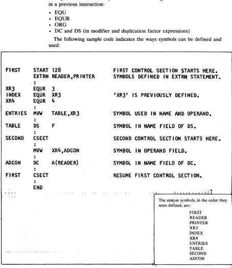
The symbols used in the operands of the following instructions must be defined in a previous instruction:
• EQD • EQUR
• ORG
• DC and DS (in modifier and duplication factor expressions)
The following sample code indicates the ways symbols can be defined and used:
START 128
FIRST CONTROL SECT I ON STARTS
HE,RE.
SYMBOLS DEFI NED IN EXTRti STATEMENT •
EXTRN READER,PRINTER
.
,
.
EQ.UR 3
EQ.UR XR3
EQUR
It
HVW
TABLE,XR3
DS
F
CSECT
HVW
XR4,ADCON
DC
A(READER)
CSECT
END
IXR3
1IS PREVIOUSLY DEFINED.
SYMBOL USED IN NAME AND OPERAND.
SYMBOL IN NAME FIELD OF OS.
SECOND CONTROL SECTION STARTS HERE.
SYMBOL IN OPERAND FIELD.
SYMBOL IN NAH£ FIELD OF DC.
RESUME FI RST
CO.NTROL
SECT ION.
I i I ' I I I I i I t i I I I
r1
The unique symbols, in the order they were defined, are:
FIRST READER PRINTER XR3 INDEX XR4 ENTRIES TABLE SECOND ADCON
Locatioll COIIllter lleferellce
The assembler maintains a location counter to assign storage addresses to your program statements. You can refer to the current value of the location counter at any place in a source module by specifying an asterisk as a term in an operand.
As the instructions and constants of a source module are being assembled, the location counter has a value that indicates a location in storage. The assembler increases the location counter according to the following rules:
[image:30.615.114.568.73.598.2]LOCATION EQ.U
AWl
B
lOCAD
DC
lOC2
DC
*
• The location counter always points to the first byte of the instruction being assembled.
• All references to the location counter in the operand field are relative to the
first byte of the instruction being assembled. (" ,
• If the statement is named by a symbol, the value of the symbol is the value of \
J
the location counter.The assembler maintains a location counter for each control section in the source module. (For complete details about the location counter setting in control sections, see "Program Sectioning" in Chapter 5.) The assembler maintains the intemallocation counter as a 16-bit value. If you specify addresses greater than 65,535, the assembler issues the error message 'CPA205S LOCATION
COUNTER ERROR'.
You refer to the location counter reference by coding an asterisk (*). Code an asterisk as a relocatable term only in the operands of:
• Machine instructions • DC and DS instructions
• EQU, ORG, and USING instructions
The value of the location counter reference (*) is the current value of the location counter when the asterisk is specified as a term. The asterisk has the same value as the address of the first byte of the instruction being assembled. For the value of the asterisk in address constants with duplication factors, see "A-type Address Constant" in Chapter 5.
Coding an asterisk in the operand of an assembler language instruction or a machine instruction (as part of an address) is the same as placing a symbol in the name field of the same statement and then using that symbol in the operand. Be careful how you use this technique; inserting or deleting instructions between an instruction and the location it refers to makes the displacement from the location
counter invalid. t
"
.
*
-1, R1
LOCATION
BRANCH TO
AWl
INSTRUCTION
A(LOCAT ION)
ADDRESS OF
AWl
INSTRUCTION
A(*}
ADDRESS OF LOC2--SAHE AS CODING:
LOC2
DC A(LOC2)
Symbol
Lellgtll Anrib.te Referellce
2 - 12 SC34-0124
When you reference the length attribute of a symbol, you get the length of the instruction or data referred to by the symbol. You can use this reference as a term in instruction operands to:
• Specify storage area lengths
o
c
Specifkations for Length Attribute References
You must code a length attribute reference according to the following rules. • The format must be L' immediately followed by a valid symbol.
• The symbol must be defined in the same source module in which the symbol length attribute reference is specified.
• The symbol length attribute reference can be used in the operand of any instruction that requires an absolute term.
The value of the length attribute is normally the length, in bytes, of the storage area required by an instruction, constant, or field represented by a symbol. The assembler stores the value of the length attribute in the symbol table along with the address value assigned to the symbol. When the assembler encounters a symbol length attribute reference, it substitutes the value of the attribute from the symbol table entry for the symbol specified in the reference.
The assembler assigns the length attribute values to symbols in the name field of instructions as follows:
• For machine instructions, it assigns a value of 2, 4 or 6 depending on the length of the instruction.
• For the DC and DS instructions, it assigns either the length or explicitly specified length of the first operand. The length attribute is not affected by a duplication factor.
• For the EQU instruction, it assigns the length attribute value of the leftmost or only term in the operand.
MACHA MACHB DISPO CHAR4 DUPLC INPUT AREAl AREA2 AREA3 CABCD TERM2 TERM3 TERM4 SDTH1 SDTI12 ;'~ SDTH3 LOCAT
LNGHl
lOAOX LATTRMVW 01 SP ,R5 IR Rl,R3
DC A(OTHER) DC C'ABCDI
DC 3F1
200' OS CL40 OS OCL40 OS 40c OS 4XL2
EQU EQU EQU EQU EQU EQU EQU • 2
Leftmost or only term
EQU
DC
Dr. MV"'I F.QU A(L'LNGH1) CL2I TEXT 'L1LO.AOX,R4
t.ILOADX
Value of symbol length attribute (at assembly time)
GENERATES A FOUR BYTE INSTRUCTION. L'MACHA=4 GENE RATES A TWO BYTE I NSTRUCT ION. L'MACHB = 2
I MPL I CIT LENGTH OF TWO BYTES L'DISPO = 2 IMPLICIT LENGTH OF FOUR BYTES VCHAR4=4 I MPL I CIT LENGTH NOT AFFECTED BY DUP. L'DUPLC =2 EXPL I CIT LENGTH SPEC I F I ED. L'INPUT =40 NOT AFFECTED BY DUPL I CAT ION FACTOR. L'AREAl =40
I MPL I CIT LENGTH OF ONE BYTE L'AREA2 = 1 EXPLICIT LENGTH NOT AFFECTED BY DUP. VAREA3=2
S I NGI,E TERti. L'CABCD = 4
TWO TERMS, LENGTH OF LEFTt10ST ONLY. L'TERM2 = 4 TWO TERHS, LENGTH OF LEFTHOST ONLY. L'TERM3 = 1
SINGLE TERti. L'TERM4 = 1
SINGLE SELF-DEFINING TERM.
MULTIPLE TERMS, LEFTMOST IS SELF-DEFINING.
CHARACTER SELF-DEFINING TERM.
LOCATION COUNTER REFERENCE • LENGTH OF CURRENT INSTRUCTION.
LENGTH OF CURRENT INSTRUCTION.
LENGTH 0F
A
LEN~THATTRIPUTE.
VSDTMI = 1
VSDTM2=1 L'SDTM3 = 1
L'LOCAT= 1 L'LNGHI = 2
I L'LOADX=4
!
L'LATTR= 1Other Attribute Refere.ces
Other attributes describe the characteristics and structure of the data you define in a program (for example, the kind of constant you specify or the number of characters you need to represent a value). These attributes are the type (T), count (K), and number (N) attributes.
You can refer to these attributes only in macro definition statements; for full details, see "Data Attributes" in Chapter 6.
2 - 14 SC34-0124
c
c
Self -de/;";"g Terms
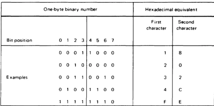
A self-defining term lets you specify a value explicitly. With self-defining terms, you can specify decimal, binary, hexadecimal, EBCDIC character data or ASCII character data. These terms have absolute values and can be used as absolute terms in expressions to represent bit configurations, absolute addresses, displacements, length or other modifiers, and duplication factors.
Self-defining terms:
• Represent machine language binary values
• Are absolute terms; their values do not change upon program relocation • Are padded on the left with zeros if less than one word
The assembler maintains the values represented by self -defining terms to 16 bits; self-defining terms are always considered as positive values in the range zero through 65,535.
A decimal self-defining term is an unsigned decimal number. The assembler allows:
• High-order zeros
• A maximum of five decimal digits
• A range of values from zero through 65,535
Note. A negative number is specified as an expression. For details, see
"Expressions" later in this chapter.
kR~l ~
·
EQ.UR
jJl3
§:r~~~":,',,
'
~Q.~
65535
HIGH-ORDER ZEROS.
~ ) ; i
5 DIGITS IS MAXIMUM VALUE.
A binary self-defining term must be coded as the letter B followed by 1-16 binary digits enclosed in apostrophes. For example:
Binary self Binary defining term value
B'1111100' 00000000 01111100
B'100' 00000000 00000100
B'l' 00000000 00000001
The assembler assembles each binary digit exactly as specified.
A hexadecimal self-defining term must be coded as the letter X followed by 1-4 hexadecimal digits enclosed in apostrophes. For example:
Hexadecimal
self-defining Binary
term value
X'FFAO' 11111111 10100000
X'F' 00000000 00001111
X'C01' 00001100 00000001
X'7FFF' 01111111 11111111
X'8000' 10000000 00000000
X'O' 00000000 00000000
2 - 16 SC34-0124
An EBCDIC character self-defining term must be coded as the letter C, followed by 1 or 2 characters enclosed in apostrophes. When assembling EBCDIC character constants, the assembler:
• Allows any of the 256 8-bit combinations as input. This includes the printable
(lJi:
characters, including blanks and special characters. " • Assembles each character into its 8-bit EBCDIC equivalent.• Requires that two ampersands or two apostrophes be specified in the character sequence for each ampersand or apostrophe required in the assembled term.
Character Characters Hexadecimal Binary self-defining assembled value value term
C'AB' AB X'C1C2' 11000001 11000010
C'C' C X'C3' 00000000 11000011
C'3' 3 X'F3' 00000000 11110011
C'D2' D2 X'C4F2' 11000100 11110010
C' , blank X'40' 00000000 01000000
C'#' # X'7B' 00000000 01111011
C'&&' & X'50' 00000000 01010000
C"" , X'7D' 00000000 01111101
C'L'" L' X'D37D' 11010011 01111101 C'5&&' 5& X'F550' 11110101 01010000
An ASCII character self-defining term must be coded as the letter S, followed by 1 or 2 characters enclosed in apostrophes. When assembling ASCII character constants, the assembler:
• Allows any of the 256 8-bit EBCDIC characters as input. This includes the printable characters, including blanks and special characters.
• Assembles each character into its 8-bit ASCII equivalent (7 bit character code (., with high-order zero bit). All characters for which there is not ASCII " equivalent will assemble as an ASCII blank character code (X'20').
• Requires that two ampersands or two apostrophes be specified in the character sequence for each ampersand or apostrophe required in the assembled term.
Examples:
ASCII self-defining Characters
term assembled Hex value Binary value
S'AB' AB X'4142' 01000001 01000010
S'C' C X'43' 00000000 01000011
S'3' 3 X'33' 00000000 00110011
S'R3' R3 X'5233' 01010010 00110011
S' , blank X'20' 00000000 00100000
S'#' # X'23' 00000000 00100011
S'&&' & X'26' 00000000 00100110
S' '" X'27' 00000000 00100111
S'I' , , I' X'4927' 01001001 00100111 S'7&&' 7& X'3726' 00110111 00100110
The assembler maintains the values represented by self -defining terms as 16 bits.
Expressions
.
.
ADDRESS
HVW
VALUE
HVWI
LENGTH
OS
FACTOR
OS
OPERAND EQU
Abso"'te
ExpressiolU
c
You can use an expression to code: • An address
• An absolute value • An explicit length • A length modifier • A duplication factor • A complete operand
You can write an expression with a simple term or as an arithmetic combination of terms. The assembler reduces multiterm expressions to single values. Thus, you do not have to compute these values. For example, expressions are used in the following instructions as indicated:
R2,DATA+4
EXPRESSION USED AS AN ADDRESS.
5+2,R3
AS AN ABSOLUTE VALUE,
CL(ALPHA-BETA)
AS AN EXPLICIT LENGTH,
(ALPHA-BETA+2)C
AS A DUPLICATION FACTOR,
LABEL+l
OR AS A COMPLETE OPERAND.
Expressions have absolute or relocatable values. Whether an expression is absolute or relocatable depends on the attributes of the terms it contains. You can use the absolute or relocatable expressions described in this section in a machine instruction or any assembler instruction other than a conditional assembly instruction. The assembler evaluates relocatable and absolute
expressions at assembly time. Throughout this manual, the word "expressions" refers to these types of expressions.
Note. The three types of expressions that you can use in conditional assembly instructions are arithmetic, logical, and character. They are evaluated at
preassembly time. In this manual they are always referred to by their full names; they are described in detail in Chapter 6.
An expression is absolute if its value is not changed by program relocation; it is relocatable if its value is changed upon program relocation.
The assembler reduces an expression to a single absolute value if the expression: • Is composed of a symbol with these values, a self -defining term, or any
arithmetic combination of absolute terms
• Contains relocatable terms, alone or in combination with absolute terms, and if all these relocatable terms are paired
An expression can be absolute even though it contains relocatable terms, provided that all the relocatable terms are paired. The pairing of relocatable terms cancels the effect of relocation. The assembler reduces paired terms to single absolute terms in the intermediate stages of evaluation. The assembler considers relocatable terms as paired under the following conditions:
Register Expressions
• The paired terms must have opposite signs after all unary operators are
resolved. In an expression, the paired terms do not have to be contiguous; that is, other terms can come between the paired terms.
• The value represented by the paired terms is absolute.
You may code register references as expressions by following the rules for coding absolute expressions. There must be at least one register symbol present in the expression to give it the register attribute.
Note. To ensure accuracy of the cross reference listing, code the register symbol as the first term of a register expression.
The following sample code shows some relocatable and absolute terms:
FIRST
CSECT
ABLE
OS
BAKER
OS
CHARLIE OS
LOCREF
EQU
ABSA
EQU
ABSB
EQU
ABSC
EQU
ABSD
EQU
ABSE
EQU
EXAMPLE 1 EQU
EXAMPLE2 EQU
EXAMPLE3 EQU
EXAMPLE4 EQU
SECOND
DELTA
EASY
FOX
2 - 18 SC34-0124
CSECT
OS
OS
OS
END
F
ABLE, BAKER, CHARLIE, AND LOCREF
F
ARE RELOCATABLE TERMS THAT CAN BE
F
PAIRED IN THE SAME EXPRESSION.
*
LOCATION COUNTER REFERENCE
XIFFf1~1
ABSA, ABSB, AND ABSC ARE
128
EQUATED TO ABSOLUTE TERMS.
C lAB'
BAKER-ABLE
ABSD AND ABSE ARE EQUATED TO
*-CHARLIE
PAIRED RELOCATABLE TERMS.
ABSA
THE OPERANDS OF EXAMPLE 1 ,
15
EXAMPLE2, EXAMPLE3, AND
ABSA+ABSC*5
EXAMPLE4 ARE ABSOLUTE