ISSN(Online) : 2320-9801
ISSN (Print) : 2320-9798
I
nternational
J
ournal of
I
nnovative
R
esearch in
C
omputer
and
C
ommunication
E
ngineering
(An ISO 3297: 2007 Certified Organization)
Vol. 4, Issue 4, April 2016
Brief Survey on Rate Adaption Techniques
with Adaptive Modulation
Suhasini N
PG Scholar, Dept. of ISE, NMAMIT, Nitte, Udupi, Karnataka, India
ABSTRACT: Modulation is nothing but a transmitting process of data from information source to the information
destination. Adaptive Modulation and Coding (AMC) is a choice of modulation, signal depending on the channel condition. This paper analyses different modulation techniques and adaptive modulation techniques for wireless network. According to the particular instant of channel condition Adaptive modulation provides different modulation scheme and modulation level. To take the advantage of good channel condition and to increase the throughput, modulation at high data rate or higher order modulations are chosen when received signals are not faded. Modulations are shifted to lower order modulations as the received signals are faded, hence the bandwidth utilization is reduced.
KEYWORDS: Adaptive Modulation, Fading Channel, Spectral Efficiency, Bit Error Rate (BER).
I. INTRODUCTION
The communication era in which everything may be audio, video, or data which is information in the form of electrical signal need to be transmitted between one or more source to destination. The problems like spectral congestion, co-channel interference, noise corrupted data reception etc, are the big threats to this communication system. This resulted in need of an encoding technique called modulation techniques. The design of communication system is decided by the type of signal. Digital modulation technique becomes more evident over analog since it provides immunity to the noise and provides bandwidth efficiency. The noise, interference, hardware problems are reduced in digital signal compared to analog signal which require larger bandwidth to transmit symbol for large number of waveform [1].
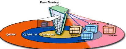
In recent years research has been undertaken targeting on improving spectral efficiency so that within given bandwidth higher data rates are achieved. Focusing on inherent capacity of underlying channel, based on link quality technique which support and adjust to the transmission parameter (in real time) have been proposed. This feature totally called as “Adaptive Modulation and Coding” (AMC) technique and based on the feedback information and in accordance with targeted Quality of Service, they provide the values of transmission parameter to be employed in the following transmission period as output [2]. Full channel capacity utilization can be given in two ways in the presence of multipath fading and interference from other user. They are adaption and diversity technique. By adaption refer to adapt different modulation by transmitter according to channel condition.
Figure 1: Illustration of Adaptive Modulation and Coding
ISSN(Online) : 2320-9801
ISSN (Print) : 2320-9798
I
nternational
J
ournal of
I
nnovative
R
esearch in
C
omputer
and
C
ommunication
E
ngineering
(An ISO 3297: 2007 Certified Organization)
Vol. 4, Issue 4, April 2016
utilization is reduced. This schema is used to reduce multipath fading and other interference in the system. For the better transmission of data at higher rate in accordance to the state of channel, this way is a better to optimize the modulation schema [3].
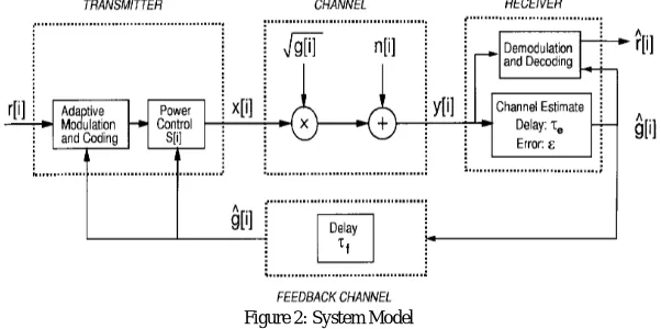
Figure 2: System Model
Figure 2 shows the system model of Adaptive Modulation and Technique. Here the from transmitter to receiver input message is sent. At time i the input message is encoded as x and sent as x[i] over time varying channel. Over the transmission of codeword channel gain g[i] changes. At time i the receiver to know the channel power gain g[i] perfect instantaneous channel estimation is assumed. It also consider the case when g[i] is known to both the receiver and transmitter at time i, as could be obtained through an error-free delay less feedback path. This allows the transmitter to adapt x[i] to the channel gain at time i, and is a genuine model for a slowly varying channel with channel estimation and transmitter feedback [4].
At transmitter AMC must require channel state information (CSI); this can be obtained by having information about channel condition at receiver and its feedback to the transmitter. So related to channel characteristics transmission schema is adapted. Depending on the average power constraints, Bit Error Rate (BER), maximizing spectral efficiency, predicted SNR, adjustment of modulation schema is done during the transmission process. Modulations like QPSK, QAM with different constellation are chosen in the transmitter. Below figure 3 gives a block diagram of adaptive modulation schema [5].
Figure 3: Block Diagram of Adaptive Modulation Schema
II. RELATED WORK
ISSN(Online) : 2320-9801
ISSN (Print) : 2320-9798
I
nternational
J
ournal of
I
nnovative
R
esearch in
C
omputer
and
C
ommunication
E
ngineering
(An ISO 3297: 2007 Certified Organization)
Vol. 4, Issue 4, April 2016
increase the data rate. For this purpose channel estimation is done and multi-carrier with AMC is used. In this paper adaptive modulation based M-array QAM, M-PSK and M-array CPM are applied to MC-CDMA system and BER performance of all digital modulation is done. In paper [4], review of different modulation techniques is done. To implement variable rate, variable error probability and hybrid technique or variable coding different adaptive methods are used. Here in this paper focusing is on variable power techniques, description of two or three power technique is done and they are compared each other. In paper [6], over time varying fading channel survey on potential of adaptive modulation and coding is done. Performance measure of spectral efficiency is done here. Higher rate modulation mode is chosen when received signal is not faded and otherwise lower rate modulations are used. In paper [7], by observing other fading channel adaptive modulation aided. Here adaptive modulation is performed without feedback to another correlated carrier by predicting future CSI using past channel observation of one carrier. Depending on the time and frequency correlation statistical model of prediction error is developed.
III. CLASSIFICATION OF MODULATION TECHNIQUES
When there is a variation in the sinusoidal waveform to use it as a signal for conveying a message, it’s called as a modulation. High frequency sinusoidal waveform is used as carrier normally. When there is continue nous variation in carrier signal in accordance to input signal it is called as analog modulation technique and whenever there is a discrete variation it is called as digital modulation technique.
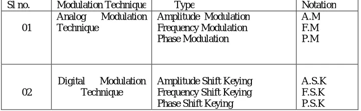
Sl no. Modulation Technique Type Notation
01
Analog Modulation
Technique
Amplitude Modulation Frequency Modulation Phase Modulation A.M F.M P.M 02
Digital Modulation Technique
Amplitude Shift Keying Frequency Shift Keying Phase Shift Keying
A.S.K F.S.K P.S.K
Table 1: Types of Modulation Techniques
3.1 ANALOG MODULATION TECHNIQUES
Analog Modulation Technique has three types, amplitude, frequency and phase modulation techniques. Amplitude modulation signal requires non-linear amplifier. It generates spurious out-of –band spectral components which are filtered out with great difficulty. For the better comparison of amplitude and phase modulation Frequency modulation technique can be used. The derivative of frequency modulation is called Narrow Band Frequency Modulation (NBFM) which is used to solve above said problem in communication system. At the receiver end these analog modulations like AM, FM,PM are sensitive to the noise present at receiver end, in contrast to this the received signal is far less sensitive to the receiver end if the digital signals are modulated and sent. This resulted in the disadvantage of analog modulation in which noise has been carried out till the end, once it has been introduce at any place in the channel for communicating over long channel [1, 8].
3.2 DIGITAL MODULATION TECHNIQUE
ISSN(Online) : 2320-9801
ISSN (Print) : 2320-9798
I
nternational
J
ournal of
I
nnovative
R
esearch in
C
omputer
and
C
ommunication
E
ngineering
(An ISO 3297: 2007 Certified Organization)
Vol. 4, Issue 4, April 2016
IV. CLASSIFICATION OF DIGITAL MODULATION
Figure 4: Classification of Digital Modulation
Figure 4 shows the full classified form of digital modulation technique. Here these digital techniques are mainly divided on the basis of amplitude, frequency, phase, continuous phase and trellis coded modulation method. QPSK and different QAM modulations like 64-QAM, 16-QAM are used in adaptive modulation process during transmission. 4.1 Binary Phase Shift Key [BPSK]
With reference to the modulated signal, when phase of a carrier wave is changed then schema is called phase shift key. The simplest form of digital modulation with two state in the carrier signal is called BPSK. In BPSK there exist two different states for each symbol or it also has one bit per symbol. The states are such as 0=0 and 180=1. Thus according to the two possible signals, according to two values, phase of a constant amplitude carrier is switched. 2-QAM modulation is also a BPSK. Balanced modulator is used to generate BPSK [9]. Carrier need to be transmitted along with signal since receiver requires referring the transmitter signal to demodulate BPSK signal. For low SNR giving power efficiency BPSK gives good BER.
4.2 Quadrature Phase Shift Key [QPSK]
For the BPSK two more phases are added and they are called as QPSK. The phases added are of 90 degree and 270 degree. So during transition two symbols are transmitted for a bit. Looking at the previous symbols present symbol phase is considered. It is a highly bandwidth efficient modulation technique since it contain four points in the constellation diagram [10]. So having high bandwidth efficiency is advantage of QPSK then BPSK. The transmitter and receiver of QPSK is complicated then a BPSK. The phase shifts are given by bit representation. For phase shift 0 degree bit representation is given as 00, bits 11 for the phase shift of 180 degree, 01 is for 90 degree and 10 for 270 degree phase shift.
4.3 Quadrature Amplitude Modulation [QAM]
ISSN(Online) : 2320-9801
ISSN (Print) : 2320-9798
I
nternational
J
ournal of
I
nnovative
R
esearch in
C
omputer
and
C
ommunication
E
ngineering
(An ISO 3297: 2007 Certified Organization)
Vol. 4, Issue 4, April 2016
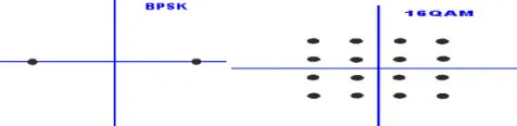
Figure 5: Constellation diagram of different modulations
Thus within different forms of QAM modulation techniques, different position of each state is represented by the constellation diagram as shown in figure 5 above. So when 1 bit per symbol is transmitted it’s given same as BPSK modulation process and as bits per symbol rate are increased, points in constellation also increase [11, 12]. Thus symbol rate and bits per symbol for different QAM modulation is shown in the table [2] below.
Table 2: Symbol rate for different modulations
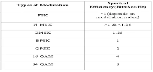
When bits per symbol are increased for different order modulation, better spectral efficiency is obtained. Thus throughput is gained. Table [3] below shows the spectral efficiency for different order modulations.
Table 3: Spectral Efficiency for different modulations
V. CONCLUSION
ISSN(Online) : 2320-9801
ISSN (Print) : 2320-9798
I
nternational
J
ournal of
I
nnovative
R
esearch in
C
omputer
and
C
ommunication
E
ngineering
(An ISO 3297: 2007 Certified Organization)
Vol. 4, Issue 4, April 2016
REFERENCES
1. D. K. Sharma, A. Mishra & Rajiv Saxena, “Analog &Digital modulation Techniques: an overview”, International Journal of Computing Science and Communication Technologies, vol.3, NO. 1, July 2010. (ISSN 0974-3375).
2. Andreas Zalonis, Natalia Miliou, Ioannis Dagres, Andreas Polydoros, and Hanna Bogucka, “Trends in Adaptive Modulation and Coding”, Advances in Electronics and Telecommunications, vol. 1, NO. 1, April 2010
3. Iftekhar Alam, Vikas Srivastva, Arun Prakash, Rajeev Tripathi, A.K.Shankhwar, “Performance Evaluation of Adaptive Modulation Based MC-CDMA System” ,Wireless Engineering and Technology, 2013, 4, 54-58
4. Lily Mishra, M.H.Patwardhan, “Review of Various Adaptive Modulation and Coding Techniques in Wireless Network”, IJRET: International Journal of Research in Engineering and Technology eISSN: 2319 - 1163 | pISSN: 2321 – 7308
5. R.Valli, P.Dananjayan, “Adaptive Modulation and Coding for Lifetime Enhancement of WSN using Game Theoretic Approach”, Wseas Transactions on Communications
6. Rohit Khajuria, Aparna Sharma, Pankaj Anand, Akhil Gupta, “A Brief Survey on Adaptive Modulation and Coding Over Time Varying Fading Channel”, International Journal of Computer Applications(0975 –8887)
7. Tung-Sheng Yang, Alexandra Duel-Hallen, and Hans Hallen. “Reliable Adaptive Modulation Aided by Observations of Another Fading Channel”, ieee transactionson communications ·may2004.
8. Assaleh, K. Farrell and R.J. Mammone, “A new method of modulation classification for digitally modulated signal”, IEEE transaction, San Diego, CA. Vol.2, pp.712-716,1992
9. Rajesh R. Bhambare, Dr. Rajeshree D. Raut, “A Survey on Digital Modulation Techniques for Software Defined Radio Applications”, IRACST – International Journal of Computer Networks and Wireless Communications (IJCNWC), ISSN: 2250-3501 Vol.3, No3, June 2013 10. A.J. Vigil, M.A.Belkerdid and D.C.Malocha, “Performance of cosine series based offset Quadrature binary modulation systems”, Military
communications conference, MILCOM-92, Conference Record-Fusing command control and intelligence: IEEE transactions,vol.1,pp.0395-0399,1922
11. RF Technology and Design, “Comparison of 8-QAM, 16-QAM, 32-QAM, 64-QAM, 128-QAM, 256-QAM, Types” httph://www.radio-electronics.com/info/rf-technology-design/
12. W. Sam, “Adaptive Modulation (QAM,QPSK)”
http://ecee.colorado.edu/~ecen4242/marko/WiMax/adaptivemodulation.pdf