Energy Consumption Analysis and Comparison of HPC and HPS of HTR-10
CAO Jianhua1, YANG Xiaoyong2, WANG Jie2 and YU Suyuan2
Abstract:In order to reduce the quantity of chemical impurities and the gaseous radionuclide fission products in the coolant helium, a helium purification system (HPS) should
be designed for high temperature gas cooled reactor (HTGR) and gas fast reactor (GFR) et al. A
HPS is mainly composed of a copper oxide bed, a molecular sieve bed and an active charcoal
bed which work under high temperature, room temperature and low temperature, respectively.
The energy consumptions of two typical HPS designs-helium pressure and chemistry control
(HPC) and the HPS for HTR-10 are analyzed and compared.
Keywords: energy consumption; helium purification system; gas cooled reactor; FFT
1. Introduction
With the development of helium gas cooled reactor, like HTGR and GFR, researchers of
different countries have extensively studied the helium purification technology [1]. There is a
HPS designed for HTTR in Japan and another for HTR-10 in China, which both have been
operating for years [2]. In France, CEA planned to build a pilot scale HPS-helium purification and
pressure control system (HPC) to demonstrate the helium purification technology after the
operation of a laboratory scale HPS-CIGNE, and the HPC is planned to be ready in use at the
beginning of 2008 [3].
In a helium gas cooled reactor, to avoid the corrosion of high temperature materials in the
reactor core and the helium-helium heat exchangers and decrease the radioactive pollution of
components in power conversion unit (PCU), the HPS is designed to purify a bypass stream from
the main helium coolant system to reduce the quantity of chemical impurities such as H2, CO,
CO2, H2O, O2, N2, CH4 and the gaseous radionuclide fission products such as Kr, Xe, etc.
These contaminants are mainly come from the new helium supply and residual air during first
load and desorption from reactor components, air in-leakage, fission products migrated from the
fuel elements, and moisture from steam generator leakage [4].
The fundamental principle of these HPS could be described into 3 parts, copper oxide beds,
molecular sieve beds and active charcoal beds [1, 2, 3]. The copper oxide bed works under high
temperature 250~350℃, to oxide the hard-adsorbed gases such as hydrogen and carbon
monoxide into easy-adsorbed gases water vapor and carbon dioxide respectively. The molecular
sieve bed works under room temperature to adsorb most of the water vapor and carbon dioxide in
the helium stream, while the liquid nitrogen-cooled active charcoal bed adsorbs the other
remained impurities at -160~-190℃.
Although with these three same beds, the detailed process designs for HPC and HPS in
HTR-10 are different. From the point of energy consumption, these two typical designs of HPS
are analyzed and compared.
2. Descriptions of HPC and HPS in HTR-10
Within the framework of R&D studies linked to the development of Generation Ⅳ nuclear
reactors, CEA has started to build up some helium loops. To test the components, representative
conditions have to be reached: temperature, pressure and chemical gaseous composition. To
control the chemical composition at impurities low level contents, HPC is designed to purify and
to adjust the composition of the helium contained in the loop. It represents 72kg/h of helium and
only the gaseous contaminants are controlled. From the point of energy consumption, the
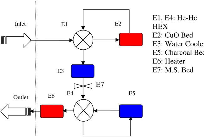
purification system of HPC is schematically shown below in fig. 1. At the end of 2006, they had
the first reception of components. And the facility will be available for its experimental program
at mid 2007 [5].
Figure 1 scheme of energy components of HPC E1, E4: He-He HEX
E2: CuO Bed E3: Water Cooler E5: Charcoal Bed E6: Heater
E7: M.S. Bed
E7
E2
Inlet E1
E3
Outlet E6 E4 E5
Components in red are heaters, coolers in blue and those white ones are adiabatic to
enviro
n at 2002. A HPS is designed to
reduc
. Working conditions and assumptions
pical HPS are slightly different for the three
adsor
nment. There are same rules in the following drawing.
In China, HTR-10 reached its first full-power operatio
e the quantity of chemical impurities in the primary coolant helium and to remove the
gaseous radionuclide fission products. This actual purification train is designed for a helium flow
rate of 10.5kg/h, corresponding with a 5% gas fraction of the helium inventory in primary circuit.
It is anticipated that more than 2000h continuous purification operation will be reached between
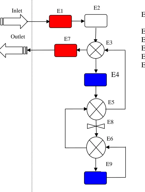
regeneration [1, 4]. The HPS is shown schematically in fig. 2 below.
Figure 2 scheme of energy components of the HPS in HTR-10
E3
Inlet E1 E2
E3, E5, E6 EX E2
ler
ed E4
E7
E8 E5
E6 Outlet
E9
: He-He H : CuO Bed E4: Water Coo E1, E7: Heater E8: M.S. Bed E9: Charcoal B
3
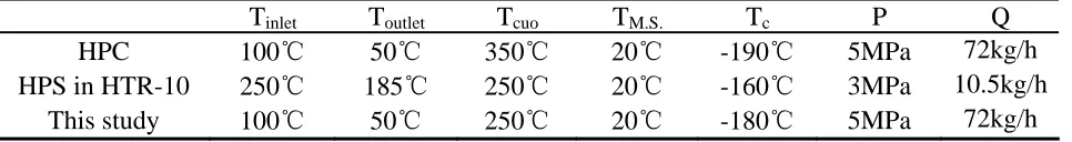
The working conditions of these two ty
ption beds, but quite different in temperatures at inlets and outlets, see table 1 below. The
outlet temperature of HPC is considered not to be too high for a helium circulator, while HPS
could have a higher outlet temperature due to its different helium circulator location.
Table 1 Working conditions of HPC and HPS in HTR-10
Tinlet Toutlet Tcuo TM.S. Tc P Q
HPC 100℃ 50℃ 50℃3 20℃ 90℃-1 5MPa 72kg/h
HPS in HTR-10 250℃ 185℃ 250℃ 20℃ -160℃ 3MPa 10.5kg/h
This study 100℃ 50℃ 250℃ 20℃ -180℃ 5MPa 72kg/h
According to the established knowledge on copper oxide bed, when the operation
tempe
he HEX) are
adiab
e
long o
. Results and comparisons
ervation, the energy consumptions of these two designs are
calcu
α
because of fixed temperatures at both inlet and copper oxide bed without any HEX between. rature is over 200℃, there would be a perfect oxidation of hydrogen and carbon monoxide.
With higher operation temperature, the capacity of hydrogen and carbon monoxide that could be
transformed by the same weight copper oxide would increase [6]. To keep a balance of these two
working conditions, the analysis was done under given conditions in table 1 above.
It’s assumed that for both systems, all the helium-helium heat exchangers
(he-atic to environment and have an initial recuperating efficiency (α) of 95%, without any
pressure drops; the working temperatures for all these three beds are fixed during the operation
period; the constant-pressure specific heat is constant at a value of 5.19kJ/(kg. K); to make an
equal comparison of two processes, the mass flow rate is set according to that of HPC, 72kg/h.
Finite-time thermodynamics method is adopted in solving these two models [7]. Within th
peration period of the reactor, the α of the he-he HEX could decrease, so the analysis was done considering α decreasing down to 50%, which means the he-he HEX works with a quite
bad performance.
4
From the view of energy cons
lated with finite-time method. The total energy consumption is defined as the algebraic sum
of all the coolers and heaters in the system. The energy consumptions of each energy
components in the systems are shown in fig. 3 and fig. 4 for HPC and HPS in HTR-10,
respectively. It can be seen from fig.3 that, all of the four energy components in HPC, would
have lower energy consumptions with higher α, so as the total energy consumption of the system.
It’s an inversely-proportional relationship between the energy consumptions of each component
and α. Under its designed working condition, HPC could have quite small energy need for both
copper oxide bed heater (red line+ symbol) and the liquid nitrogen cooler (blue line+ symbol).
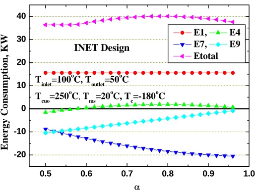
For HPS, the copper oxide bed heater has constant energy consumption with various
50
0.5 0.6 0.7 0.8 0.9 1.0 -20 -10 0 10 20 30 40 T inlet=100 o C, T outlet=50 o C T cuo=250 o C, T
ms=20 o C, T c=-180 o C Ener
gy consumption, KW
α E2 E3 E5 E6 Etotal CEA Design
Figure 3 Energy consumption of HPC
With an increasing α, HPS would have a smaller liquid-nitrogen cooler and a bigger water
cooler at the outlet due to h EX cold ide with steady
tempe
igher temperature at the outlet of E3 H -s
rature at inlet of hot-side from copper oxide bed.
0.5 0.6 0.7 0.8 0.9 1.0 -20 -10 0 10 20 30 40 INET Design T inlet=100 o C, T outlet=50 o C T cuo=250 o C, T
ms=20 o C, T c=-180 o C E n
ergy Consumption, KW
α
E1, E4 E7, E9 Etotal
Figure 4 Energy consumption of HPS in HTR-10
5. Conclusion
nergy consumptions of HPC and HPS of HTR-10, have been analyzed and calculated as
an adiabatic process by finite time thermodynamics (FTT), considering the heat resistance losses E
in the
gy consumptions of each
n HPC;
Refer
[1] Yao M, Wang R, Liu Z, et al. (2002). The helium purification system of the HTR-10.
neering and Design, 218: 163~167
esign, Vol. 233: 147~154
technology, October
1-4, 2
363~365
ting on high temperature reactor technology,
Octob
r. Atomic Energy Science and Technology, Vol.
29 (5
ique, Vol. 35: 647~650
HE-HE Heat Exchangers (HEX), and free of pressure drop and gas leakage, under a
typical working conditions of HPS with different efficiencies of HEX.
The results show that:
1. It’s an inversely-proportional relationship between the ener
component and α i
2. The total energy consumption in HPS of HTR-10 is not sensitive to α, even when α is
as low as 50%;
3. Less energy consumption of HPC, compared to HTR-10 design, is based on high α;
ences
Nuclear Engi
[2] Nariaki S, Takayuki F, Taiki K, et al. (2004). Short design descriptions of other
systems of the HTTR. Nuclear Engineering and D
[3] Olivier Gastaldi, Karine Liger, Jean Charles Robin, et al. Helium purification.
Proceedings: 3rd international topical meeting on high temperature reactor
006, Johannesburg, South Africa
[4] Zhou J, Wang M, Zeng H, et al. (2003). Helium purification system for HTR-10.
Nuclear Power Engineering, Vol. 24(4):
[5] Fanny Legros, Karine Liger, Christian Poletiko, et al. Helium purification at laboratory
scale. Proceedings: 3rd international topical mee
er 1-4, 2006, Johannesburg, South Africa
[6] Liao C, Zheng Z, Shi F (1995). Study on the conversion of H2 and CO from the helium
carrier gas of high temperature gas-cooled reacto
): 441~448
[7] Andresen B (1996). Finite-time thermodynamics and thermodynamic length. Revue
Generale de therm