Jurnal Mekanikal Jun 2003, Bil.15,42 -57
A
PRELIMINARY STUDY INTO THE APPLICATION OF
ACTIVE FORCE CONTROL STRATEGY TO AN
AUTOMOTIVE SUSPENSION SYSTEM
Zamri Omar Faculty of Engineering
KolejUniversiti Teknologi Tun Husseinann Beg Berkunci 101
86400 Parit Raja, Batu Pahat
MusaMailah
Department of Applied Mechanics Faculty of Mechanical Engineering
Universiti Teknologi Malaysia 81310 Skudai
ABSTRACT
This paper describes a novel approach to control an automotive suspension system employing activeforce control (AFC) strategy.AFChasbeen demonstratedtobe veryrobust andeffec tive in controlling dynamical system subject to disturbances, uncertainties, parametric changes and operating conditions.In the study,AFCis explicitlyimplemented toprov idea robust mechanism for the control of the suspension system that is subjected to a number of operating and loading condit ions pertainin g to road input disturbance and deliberat ely introduced exte rnal disturbances.The classical proportional and derivative (PD) controllerisalso incorporated into the control scheme that could further enhance the effec tiveness of the proposed method. An iterati ve learning technique was embedded into the control loop to obtain the estimated mass requiredby the AFC strategy to effect the control action.A modellingand simulat ion studywas ca rried outon a quartercar modelsystem with the applied control schemetaken into acceunt,A comparative study between the AFCand pure PD schemes was perform ed to demonstrate the differences in the performance.
1.0 INTRODUCTION
Suspension design requires a compromise between the passenger comfort and good vehicle handling. To provide a good ride comfort, the suspensio n should be soft enough, whereas good road holding requires stiff suspension. The main requirements of a vehicle suspension are that it should be able to minimize the vertical displacement and the acceleration of the body. These are to increase the passenger comfort, to minimize the dynamic tyre load to provide maximum road holding and react to the changes of mass payloads [1]. Due to these conflicting demands, suspensio n design has had to be something of a compromise, which is largely determined by the type of vehicle usages. Several approaches have been
Jurnal Mekanikal, Jun 2003
proposed as the control model on the active suspension system. Palmeri et. al. [2] proposed a fairly robust control model-based method using Hi; technique involving a multi-input-single-output (MISO) regulator. A comparative study was made between active and passive suspension systems with the former showing a very significant result. Ono et. al. [3] employed a distributed hiearchy control of active suspension system that showed the attenuation of the road vibration and improvement in vehicle attitude. In another work, a digital control vehicle active suspension system was performed incorporating a hydro-pneumatic slow active suspension with its analogue controller structure [4] embedding the classical PD and PI control elements plus preview control. Experimental results show satisfactory performance in line with the theoretical prediction. Wendel and Stecklein [5] came up with a regenerative pump concept as the active element of the sj'stem unlike the traditional hydraulic actuator that is almost universally used in the study of active suspension. However, this approach is still in its infancy stage due to some of the physical constraints encountered.
In this study, a robust method known as active force control (AFC) [6] is employed to control the performance of an automotive suspension system considering varied loading and operating conditions. The varied conditions of the car were simulated by applying several types of external disturbances in the forms of road input and the application of external forces. The preliminary study conducted here only considered the vertical displacements of the body during its operation. The paper is organised as follows. It starts with the definition of the problem statement and the description of the fundamental of the AFC method. The mathematical model governing the equations of motion of an automotive suspension system in the form of a quarter-car model is then described. This is followed by the narration of the assumptions made, the disturbance models and the control strategy used in the study. Consequently, a simulation study that includes a description of the parameters employed in the simulation process and the development of the SIMULINK model of the proposed control method are explained. Finally, the discussion of the results obtained is given and a conclusion with suggestions for future work is presented.
2.0 PROBLEM DEFINITION
Jurnal Mekanikal, Jun 2003
3.0 ACTIVE FORCE CONTROL
Hewit and Burdess [6] proposed an active force control (AFC) strategy to control a dynamic system in order to ensure the system will remain stable and robust in the presence of known and unknown disturbances. Musa [7] has demonstrated that AFC is superior compared to the conventional method in controlling a robot arm. The underlying concept of AFC is that it uses some measured and estimated values of the identified system parameters namely, the actuated force, acceleration and the estimated mass of the body.
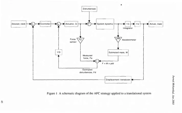
Figure 1 illustrates the application of AFC to a dynamic translational system assuming a trajectory tracking control task. The physical quantities which need to be measured directly from the system are the actuated force, Fa and the linear
acceleration, a which could be accomplished using some sensing elements .such as a force sensor and an accelerometer. Then, the estimated mass, M required by the AFC strategy should be appropriately estimated using suitable methods such as the crude approximation technique and intelligent means [7]. By doing this, the compensated or estimated disturbance, Fd could be obtained indirectly
through the following expression,
(1)
The above equation, if properly obtained contribute to a very robust performance of the dynamic system even in the presence of known and unknown disturbances [6,7]. In the study, the dynamic system to be considered is an automotive suspension system that is subjected to external forces. The main drawback of the AFC method is the need to appropriately estimate the mass required by the strategy to be fed into the forward control loop for the compensation of the external disturbances. In this simulation study, an iterative learning method was used to approximate the estimated (sprung) mass of the system. The controller shown on the left of Figure 1 can be easily the
conventional PD type. •
4.0 THE SUSPENSION SYSTEM MODEL
The mathematical model of the suspension system is developed from the fundamental principle of the dynamic system. Firstly, a suitable model of the suspension system with the exertion of all the related forces was considered. The model of the automotive suspension system is derived from a quarter car model as shown in Figure 2. The suspension spring with stiffness K, and damper with damping coefficient, C are installed in parallel between the sprung (Ms) spacing
required and unsprung (Mu ) masses. The sprung mass of a car is defined as the
mass that is carried by the suspension spring. It consists of the frame, body, engine, transmission and any other parts that moves directly with the frame and body.
~
Disturbances
Integrator
F=M xydd
System dynamic I •
.
1
Measured
force ,Fa I
1/~
Desired_track
Estimated
dis tu rbances ,Fd
I IDisplacement transducer I'" I
~
~
[
....
Figure 1 Aschematic diagram of the AFC strategyapplied to a translational system
~
[
~
...
...
furnal Mekanikal, fun 2003
Unsprung
J
XmJlss. Mu
Kt
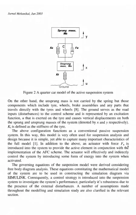
Figure 2 A quarter car model of the active suspension system
On the other hand, the unsprung mass is not carried by the spring but those components which include tyre, wheels, brake assemblies and any parts that travels directly with the tyres and wheels [8]. The ground serves as the road inputs (disturbances) to the control scheme and is represented by an excitation function, u that is exerted on the tyre and causes vertical displacements on both the sprung and unsprung masses of the system (denoted byx and y respectively).
K, is defined as the stiffness of the tyre.
The above configuration functions as a conventional passive suspension system. In this way, this model is very often used for suspension analysis and design because it is simple, yet able to capture many important characteristics of the full model [1]. In addition to the above, an actuator with force Fa is introduced into the system to provide the active element in conjunction with the implementation of the AFC scheme. The actuator will effectively and indirectly control the system by introducing some form of energy into the system when activated.
The governing equations of the suspension model were derived considering free body diagram analysis. These equations constituting the mathematical model of the system are to be used in constructing the simulation diagram via SIMULINK. Consequently, a control strategy is introduced into the suspension system to investigate the system's performance, particularly it's robustness due to the presence of the external disturbances. A number of assumptions made throughout the modelling and simulation study are also clarified in the relevant section.
JurnalMekanikal,Jun 2003
Q
i i i
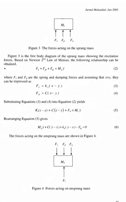
Figure 3 The forcesacting on the sprung mass
Figure 3 is the free body diagram of the sprung mass showing the excitation
forces. Based on Newton 2nd Law of Motion, the following relationship can be
obtained,
..
(
2)
where F, and Fp are the spring and damping forces and assuming that x>y, they
can be expressed as
r,
=ks(x- y)r
,
=C(x- y )SubstitutingEquations (3) and (4) into Equation (2) yields
Ks(x - y) +C(.\:-
y
)
+Fa=Ms.vRearranging Equation (5)gives
The forcesactingon the unsprungmassare show n in Figure 4.
111
[;]
r
Figure 4 Forces acting on unsprungmass
(3)
(
4)
(5)
Jurnal Mekanikal, Jun 2003
The tyre force is represented by
F, = KJu -x)
and equating the summation of forces gives
Substituting Equations (3), (4) and (7) into Equation (8) yields
Rearranging Equation (9), the equation becomes
(7)
(8)
(9)
(10)
4.1 The Actuator
The simulation study of the automotive suspension system which employed the AFC scheme is performed by employing an actuator that acts as one of the control elements in the system. The actuator has been modelled as a linear type with a suitable gain assigned which is being determined by performing a series of simulations. The actuator provides the controlled force to lift the sprung mass to a specified vertical displacement for effective position control.
4.2 Assumptions
A number of assumptions were made in the implementation of the tasks outlined in the objectives of this project. They were as follows,
i. The quarter car model is configured and assumed reasonably accurat
r
to represent the important characteristics of the full car model.11. The value of the parameters adapted from [1] were used In the
proposed study.
111. Only vertical movement of the suspension system (body) IS
considered in the study and that the suspension workspace IS
neglected.
IV. The damping coefficient of the damper remains constant during operation.
v. Unity gains were assumed for the sensors used in the study.
4.3 The Control Strategy
The proposed control strategy of the active suspension is schematically presented in Figure 5. The dotted line indicates the boundary of the control system and generally, the figure shows how the task is being implemented. By taking the desired point as the reference, the controller needs some measurements pertaining
Jurnal Mekanikal, fun 2003
to the acceleration and vertical displacement of the sprung mass in order to actuate the control signal via the actuator. These flow of information/data if appropriately and accurately conveyed will affect the controlling action of the proposed strategy. It is also important to note that the estimated mass of the system should also be appropriately acquired and later introduced into the AFC loop. If digital control is employed, most of the above parameters considered will be related to numerical data processing.
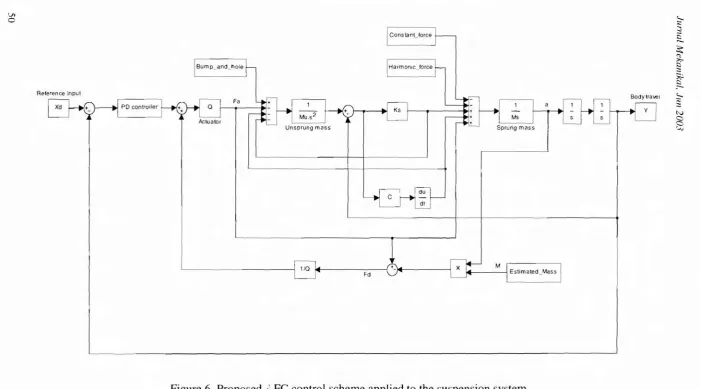
The proposed control scheme applied to the suspension system is a combination of AFC and PO controller with an iterative learning technique employed to estimate M. Figure 6 shows a block diagram of the proposed control scheme based on Equations (1), (6) and (10). It should be noted that the disturbances comprise the road input (bump and hole) and also deliberately
int~oduced external disturbances in the form of constant and harmonic forces, all of which serve as a mechanism to test the robustness of the proposed method. For the AFC loop, the force sensor and accelerometer are assumed to have unity gains, while the proportional and derivative gains, Kpand Kdfor the PO controller
have been pre-determined through a number of trial runs. The estimated mass M necessary for the AFC implementation is approximated using an iterative learning algorithm. The outermost loop represents the conventional PO control loop involving the measurement of the actual displacement of the body (sprung mass).
[_spr~ng
Mass, MuMeasurements (acceleration and
displacement)
lVleasurement
Control signal Active Force
Control (AFC)
Road input
Ul
C
Unsprungmass
,
-IConstanttorce
I
-J~~~~~~l<, :;::
::;
r::;
-~
'"
~
~
~
.
-~
N
a
a
'....,
1
-
1/0 14 (+-)l<lIl..- -- - - jFa
Jurnal Mekanikal, Jun 2003
4.4 Disturbances
Several types of disturbances have been specifically introduced to the system to examine the robustness of the proposed control system in the presence of the external disturbances. There are three types of disturbances considered in the study and they take the following forms:
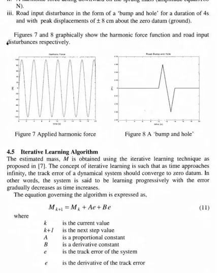
i. A constant force of magnitude 3500 N acting downward on the sprung mass. ii. A harmonic force acting downward on the sprung mass (amplitude equals 100
N).
Ill. Road input disturbance in the form of a 'bump and hole' for a duration of 4s
and with peak displacements of ±8 em about the zero datum (ground).
Figures 7 and 8 graphically show the harmonic force function and road input tlisturbances respectively.
"---C;---:---:---:---c'c,,---c,:-,----:-"-I'i;--'~B---20
lime (s)
Figure 7 Applied harmonic force
Road Bump and Hole
I 0 f - - - '
lime (s)
Figure 8 A 'bump and hole'
4.5 Iterative Learning Algorithm
The estimated mass, M is obtained using the iterative learning technique as proposed in [7]. The concept of iterative learning is such that as time approaches infinity, the track error of a dynamical system should converge to zero datum. In other words, the system is said to be learning progressively with the error gradually decreases as time increases.
The equation governing the algorithm is expressed as,
where
M
k+1=M
k+Ae+Be
k is the current value
k+1 is the next step value
A is a proportional constant
B is a derivative constant
e is the track error of the system
e is the derivative of the track error
A =600
B
=
550furnal Mekanikal, fun 2003
5.0 SIMULATION
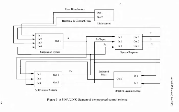
The major advantage of analyzing the response of the modelling system through the simulation is that it allows the designer to predict the behavior of the system before it is built. In this study, the MATLAB/SIMULINK software package was chosen as a tool to perform the simulation task because it offers the most powerful desirable features. Figure 9 shows the overall SIMULINK diagram comprising five sub-systems related to the suspension system model, the AFe control scheme, the iterative learning algorithm, the disturbance models and the system response. The diagrams were constructed based on the governing equations of the mathematical modelling of the sub-systems involved. Note that the input and output variables of each sub-system are also clearly indicated in the figure.
5.1 Simulation Parameters
The parameters used in this simulation are described as follows:
Suspension system (adapted from [1]):
Sprung mass, M,= 290 kg
Unsprung mass, M;
=
59 kgSuspension spring stiffness, K,
=
18812N/mDamping coefficient, C = 3000Ns/m
Tyre stiffness, K, = 250kN/m
Iterative learning algorithm: Proportional constant,
Derivative constant,
Actuator: Gain,
PD Controller: Proportional gain, Derivative gain,
x,
=29500N/mKp=0.3
Kd=0.05
Reference input function:
Reference displacement - a step function, final value
=
0.04 m52
Simulation parameters: Integration algorithm, Start time,
Stop time,
Minimum step size, Maximum step size,
: Ode 45 (Dormand-Prince) : 0.0 s
,.
~
~
~
~ ~ ;:s
~
. ' -Itreative Learning Model
Road Disturb
AFC Control Scheme
dll(;C~
Out 1 Out 2 Harmonic & Constant Force
Disturbances
y In 1
In 1 Out 1
In 2 Out 1 a Ref Input
.
vIn 2 Out 2
In 3
Fa
In 3 Out 3 v
In 4
-Suspension System System Response
Fa Estimated
In 1 Out 1 Mass
In 1
In 2 Out 1
In 3 Out 2 In 1
"
Figure 9 A SIMULINK diagram of the proposed control scheme ~;:s
lurnal Mekanikal, Jun 2003
6.0 RESULTS AND DISCUSSION
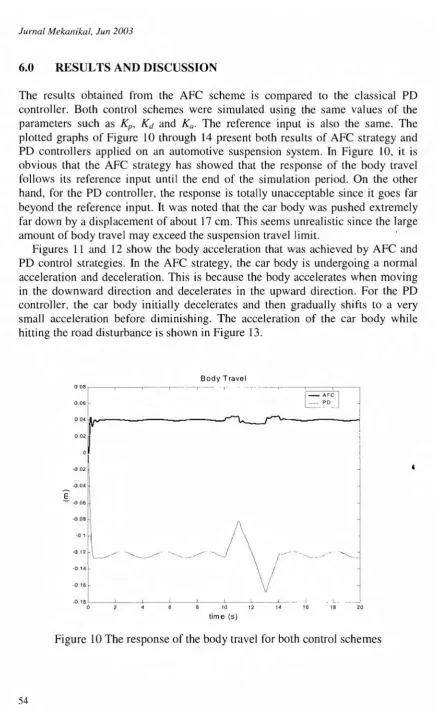
The results obtained from the AFC scheme is compared to the classical PD controller. Both control schemes were simulated using the same values of the parameters such as Kp , Kd and Ka . The reference input is also the same. The
plotted graphs of Figure 10 through 14 present both results of AFC strategy and PD controllers applied on an automotive suspension system. InFigure 10, it is obvious that the AFC strategy has showed that the response of the body travel follows its reference input until the end of the simulation period. On the other hand, for the PD controller, the response is totally unacceptable since it goes far beyond the reference input. It was noted that the car body was pushed extremely far down by a displacement of about 17 ern. This seems unrealistic since the large amount of body travel may exceed the suspension travel limit.
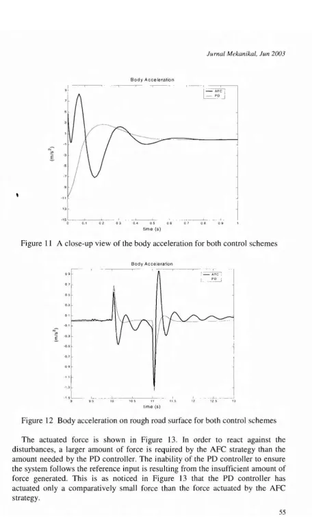
Figures 11 and 12 show the body acceleration that was achieved by AFC and PD control strategies. Inthe AFC strategy, the car body is undergoing a normal acceleration and deceleration. This is because the body accelerates when moving in the downward direction and decelerates in the upward direction. For the PD controller, the car body initially decelerates and then gradually shifts to a very small acceleration before diminishing. The acceleration of the car body while hitting the road disturbance is shown in Figure 13.
Body Travel
: : :~-~~--r---~~--r-~-- r
DD4IA~
I
l
~~:I
DD2
~DD2
~D.D4
E
~ ~DD6
-D 1
-0 12 ~D.DB
.:I
-0.18 _---'--_----'---_----'---_----'-_ _~ L - L 1 _ L__
D 4 1D 12 14 16 1B 2D
time (s)
Figure 10 The response of the body travel for both control schemes
Jurnal Mekanikal, Jun 2003
Body Acceleration
,
I
sr
1___
o 0.1 02 03
-
"---"--0.4 05
time (s)
06
--~--~
-07 08 09
Figure 11 A close-up view of the body acceleration for both control schemes
Body Acceleration
11
09~
O't·
05
0.3
01
-0.1
N .'!'. -0.3
E.
-0.5
0.'
09
11
·',.3
·15 L .
9 95
_.~----'---'---10 105
time (s)
,
11 5 , 12
'==A~
PD
-.1 _
125
Figure 12 Body acceleration on rough road surface for both control schemes
Jurnal Mekanikal, Jun 2003
6000
r-7000
6000
5000
Z 4000
Actuator Force
I-...~ l_=-P~ JI
I
I
3000
2000
1000
20
- - ~:--~
16 18 ---.L____ _...1.-_ ---.1.- ---.L_
_----.1.-_---.1-2 4 6 8 10 12 14
time (s)
o
o
Figure 13 The actuated force for both control schemes
The track error of the body travel is shown in Figure 14. The figure clearly demonstrate the effectiveness of the AFe control strategy applied to the suspension system. As the system with the PD controller is unable to follow the reference input, a high magnitude of steady state error occurs in the system as can be seen in the figure.
Track Error
03 r- - - -r-'- - - --===-=-::":.-1
- AFC I P~
0.25
02 !
I
J
OJ
-----E
°t
I
II
~
J
I
I
·005L- - .L- --"- ..L -, _ . ..l _____ I . .1 . _ 1 . . _ _1
0 2 4 6 8 10 12 14 16 1 B 20
lime (5)
Figure 14 The track error of body travel for both control schemes.
Jurnal Mekanikal, Jun 2003
6.0 CONCLUSION
In this preliminary study, the proposed AFC scheme which has been applied to an automotive suspension system has been shown to be very robust and effective in compensating the error due to the specified road input profile and the introduced external disturbances. The AFC scheme has shown that the response of the system follows satisfactorily the given reference input, whereas for the PD controller, this task cannot be achieved satisfactorily. Furthermore, the response of the system employing only classical PD controller goes far beyond the acceptable limit of the suspension workspace. The appropriate selection of the AFC parameters such as the estimated mass, actuator gain and controller gains is vital for the effectiveness of the control system. Further comprehensive and
r~orous study should include the riding performance involving more degrees-of-freedom, full suspension workspace, frequency response analysis and the application of other intelligent methods to approximate the estimated mass using the AFC strategy.
REFERENCES
1. Lin, l.S. and Kanellakopoulos, 1., 1995, "Nonlinear Design of Active Suspension", IEEE Control Systems Magazine, VoLl7, pp 45-49.
2. Palmeri, P.S., Moschetti, A. and Gortran, L., 1998, "H-Infinity Control for
Lancia Therma Full Active Suspension System", Electronic Steering and
Suspension Systems, Automotive Electronics Series, PT-77, SAE Inc., pp 315-322.
3. Ono, E., Yamashita, M. and Yamauchi, Y., 1998, "Distributed Hiearchy
Control of Active Suspension System", Electronic Steering and Suspension
Systems, Automotive Electronics Series, PT-77, SAE Inc., pp 443-448.
4. El-Demerdash, S. M., Plummer, A.R. and Crolla, D.A., 1998, "Digital
Control of Active Suspension Systems", Electronic Steering and Suspension
Systems, Automotive Electronics Series, PT-77, SAE Inc., pp 401-408.
5. Wendel, G.R. and Stecklein, G.L., 1991, "A Regenerative Active Suspension
System", Vehicle Dynamics and Electronic Controlled Suspensions, SP-861,
SAE Inc., pp 129-135.
6. Hewit, J.R. and Burdess, l.S., 1986, "An Active Method for the Control of Mechanical Systems in the Presence of Unmeasureable Forcing", Transaction
on Mechanism and Machine Theory, Vol. 21, pp 393-400.
7. Musa, M., 2000, "Intelligent Active Force Control of A Rigid Robot Arm Using Embedded Iterative Learning Algorithms", Jurnal Mekanikal, Vol. II, Universiti Teknologi Malaysia, pp 16-45.
8. Hussein, S.B., 1995, "Design, Build and Test of A Prototype Intelligent