Disparity Map Computation of Stereo Images
Rectified using SURF Technique
V Meghana, Prof. T. Ramashri, P. Janardhan Sai Kumar
M. Tech Student, Dept. of E.C.E, SVUCE, S. V. University, Tirupati, India
Professor, Dept. of E.C.E, SVUCE, S. V. University, Tirupati, India
Research Scholar, Dept. of E.C.E, SVUCE, S. V. University, Tirupati, India
ABSTRACT: Stereo vision system is used to reconstruct a 3D scene from 2D images taken by pair of optical cameras(left & right).This is used to measure the distance of the object. Finding distance between one object to another is major criteria in robot functioning to complete the given task. Disparity map is the one which helps in finding the distance of each object from optical camera[1]. A disparity map is usually obtained by stereo images using stereo matching method. Edge boundaries in the disparity map separate two different objects. Thereby edge preserving is one of the important criteria in stereo matching. Using different cost functions and matching techniques the distance of the target from camera is determined in disparity map. Previously disparity map computation is done using SAD/SSD based on the block matching technique.[1] Here, finding out the corresponding (closest match) of the block of left image in right image is the procedure. This algorithm produced good results .But the time taken to find the distance of the object from the optical camera is really long. This computation of disparity map using SAD/SSD when substituted with SURF technique yielded better results comparatively. Finally the obtained output is subjected to edge detection process so that the time lapse gets shorter.[1][2]
KEYWORDS: Stereo Images, Disparity Map, SAD, SSD, SURF, Block Matching, Edge Detection
I. INTRODUCTION
Stereoscopic vision is a technique for inferring the 3D position of objects from two or more simultaneous images of a scene. Mobile robots can take advantage of a stereo vision system as a reliable and effective way to extract 3D data from the environment[4]. Reconstruction of the image using stereo cameras can be done in two ways. One is, for each point in image and the corresponding point in the other image it computes the disparity distance in pixels of these points and the second one is given the disparity map and focal distance of the two cameras and the geometry of the stereo setting relative position and orientation of the cameras compute the world coordinates of each point in the images.[1]
Stereo matching is a problem to find similarity between two input images. It is one of fundamental computer vision problems with a wide range of applications, and hence it has been extensively studied in the computer vision field for many recent years. Stereo matching is to find for each point in the left image, its corresponding in the right one. The difference between horizontal distances of these points is the disparity[1][2]. A disparity map consists of all the possible disparity values in an image. There are some matching techniques preferred for this process, where disparity map computation using SAD/SSD based on block matching technique is the one. In the modified version the disparity map is computed with respect to the edges of the two input images. This process is carried out using two cameras (left & right) in such a way that it enhances the picture clarity using block matching.[2]
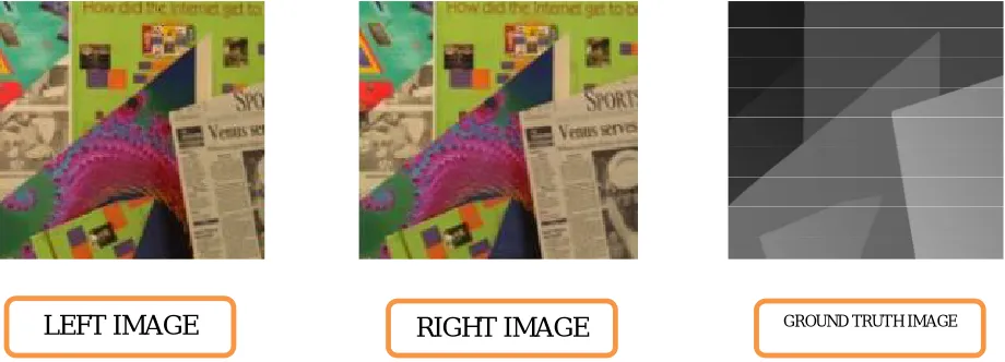
Then finally obtained disparity map is compared to ground truth image which is provided by the image supplier (the reference image) and by this how accurate the image is determined.
II.DISPARITY MAP USING SAD/SSDBASED BLOCK MATCHING
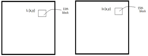
scanning the complete row one of the block positions gets approximately matched.This block is considered as the block similar to the reference block as shown in Fig 1.
Fig 1: Block matching with reference image as left image
The difference between the two blocks is calculated by,
( , , ) = | ( , )− ( , − )|
If disparity is more it is considered that the object is closer to camera, and if the disparity is less it is considered that the object is farther from the camera. If disparity is more the deviation of angle for first and second camera is more and when object is farther the deviation is not much so the disparity would be less.[2][1]
Similar to SAD there is another cost function SSD ‘Sum of Square Difference’, where square of difference of each and every block is calculated. The greater the difference between the given images the higher would be the mismatch, and the lesser the difference betweenthe images the more accurate they are. So that output obtained is more accurate in SSD comparatively. The difference is calculated by the given formula,
( , , ) = | ( , )− ( , − )|
The output obtained from computational block is subjected to edge detection process and finally we get more accurate result than previous one. The block matching technique produces approximate results but the time lapse is so long since it performs block by block matching. This problem can be overcome by using SURF (Speed Up Robust Features) technique. SURF approximates or even outperforms previously proposed schemes with respect to repeatability, distinctiveness, and robustness,yet can be computed and compared much faster.[2][6]
Both the input images (left and right) are considered where left image is taken as reference image for disparity map computation.The cost function is used to measure the similarity between the two images. Fig 2 represents the block diagram of the disparity map using SAD/SSD based on block matching.
Fig 2: computation of disparity using SAD/SSD based on block matching.
Two images left and right are taken and given as input shown in the block diagram in order to compute the disparity map using Sum of Absolute Difference /Sum of Square Difference based on block matching technique.The differences between two images are compared using SAD/SSD.Keeping in view of common portion and differences between the two images the disparity map is produced. In order to get better estimate of disparity map the initial stereo images are subjected to edge detection process and the final result obtained is even more accurate. Since in block matching each block in every single row is compared the time lapse to perform this operation is very high which is the major drawback of the block matching technique. This can be overcome by Speed Up Robust Features.
Block matching based on SAD/SSD Left
Image
Right Image
Disparity map Edge
Detectio
III.DISPARITY MAP USING SAD/SSDBASED BLOCK MATCHING OVER RECTIFIED IMAGES BY SURF TECHNIQUE
The left and right images are subjected to SURF rectification process where the important and desired features of both left and right images are compared and computated.The output of rectification block is rectification of left and right images as shown. Both these rectification left and right images are given as inputs to SAD/SSD and finally the disparity map is produced.[1]
The second case of this scenario is before giving the rectification left and right image outputs to SAD/SSD they are given to Edge detection process so that the lost edges of the image is retrieved to some extent. The block diagram represents computation of disparity map using SAD/SSD based on the SURF technique.[1][3]
Fig 3: Computation using SAD/SSD based on SURF technique.
Speed Up Robust Features:
SURF technique is used for tasks such as object recognition,image registration, classification or 3D reconstruction .To detect interest points,SURF uses an integer approximation of the determinant of Hessian blog detector which can be computed with 3 integer operations using a precomputed integral image Its feature descriptor is based on the sum of the Haar wavelet response around the point of interest. This can also be computed with the aid of the integral image.[4][6]
SURF descriptors have been used to locate and recognize objects,people or faces to reconstruct 3D scenes,to track objects and to extract point of interest. The SURF technique is basically classified into three modes of object reconstruction namely 1.Detection, 2.Description,3.Matching
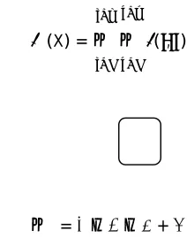
In detection process the target is detected from the given image .The target of the given image is referred as the desired region. Here object detection is done based on the integral method.
Based on the formula fed,
∑(X) = ( , )
= − − +
Fig 4: Computation of particular block D B
C A
Left Image
Right
Image
Rectificati on using SURF
Rectified leftimage
Rectified rightimage
Edge
Detection
Edge
Detection
SAD/ SSD
Disparity Map
This method involves in cumulative addition of each and every block of whole image. But the above image is computed for individual selective block.Hessian Matrix used to determine shape of the object and the area of the coverage. If we get maximum determinant at a particular position where we get blob like structures.At a given point of X(x,y).[4][5]
Hessian matrixH(x, ) = ( , ) ( , )
( , ) ( , )
( , )= ( )
Convolution of Gaussian second order ( ) ℎ ′ ′.
( , ) =
. g( )
( , ) = ( )
is standard deviation of gaussian filter
Det( ) = − −
For every location determinant is found, the maximum value represent strongest point.While description is the process that can distinguish the particular object in which it is aligned in finding the peculiar direction or shape of the object.
Matching is the process which is to make fast access that is fast matching of the desired image .Through all these processes,that the image that has undergone closest match of the image is determined. The final output is then compared to the provided ground truth map to obtain the measure of accuracy.[6]
IV.RESULTS AND DISCUSSION
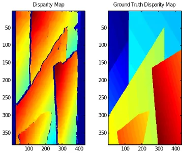
The disparity maps obtained using block matching technique and SURF techniques are displayed below. It is observed that the results obtained through block matching technique lapsed for long time period and moreover the quality of accuracy is low. Whereas in case of SURF technique the required portion of the image is computed and so, the time lapse is much shorter with noticeable improvement in quality of the disparity map.
Fig 5: The input left and right images along with its ground tooth image
Fig. 6. Disparity map based SAD/SSD in block matching technique
Fig. 7. Disparity map based SAD/SSD in block matching subjected to Edge detection
Fig 8. Disparity map based SAD in SURF technique Fig. 9. Disparity map based SSD in SURF
Fig 10. Disparity map using SURF subjected to Edge Detection
The above results are calculated for three different parametric measures namely SSIM, Ordinal Measure and Time Taken so that the accuracy of the disparity map and time laps is determined.
Disparity Map using SSD
200 400 50 100 150 200 250 300 350 0 5 10 15 20 25 30 35 40
Disparity Map using SAD
200 400 50 100 150 200 250 300 350 0 5 10 15 20 25 30 35 40
Ground Truth Image
200 400 50 100 150 200 250 300 350
Disparity Map using SSD
200 400 50 100 150 200 250 300 350 0 5 10 15 20 25 30 35 40
Ground Truth Image
100 200 300 400 50 100 150 200 250 300 350 Disparity Map
100 200 300 400 50 100 150 200 250 300 350
Ground Truth Disparity Map
100 200 300 400 50 100 150 200 250 300 350 Disparity Map
100 200 300 400 50 100 150 200 250 300 350
Ground Truth Disparity Map
100 200 300 400 50 100 150 200 250 300 350 Disparity Map
100 200 300 400 50 100 150 200 250 300 350
Ground Truth Disparity Map
Ordinal Measure:
Measure of relative maximum deviation which is mathematically given by
OM = MaxunumDeviation NumberofTotalPixels
By this how far the obtained image is deviated from reference one is determined.there by the efficiency of the image is estimated.
Structural Similarity Index Measure:
SSIM = ( )( )
( )( )
WhereX Is Obtained Disparity Map& Y Is Reference Map
Means the mean of the image ’x’ =
=covariance coefficients of image x and image y
= E[(X- ) − =E[XY] −
= = [( − )^2 ] = E[ ]−
= = [( − )^2 ] = E[ ]−
= ( )^2
= ( )^2
By default & values are 0.01& 0.03
Where L is dynamic range of pixel value, L=2 −1 for an 8 bit image.
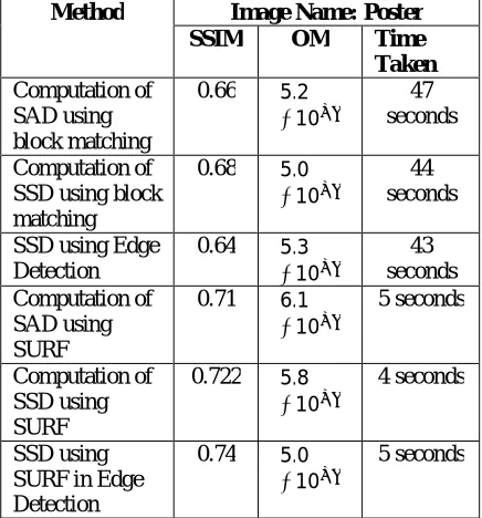
TABLE I: Computational comparison of block matching & surf technique using SAD/SSD
Method Image Name: Poster SSIM OM Time Taken Computation of
SAD using block matching
0.66 5.2
∗10
47 seconds
Computation of SSD using block matching
0.68 5.0
∗10
44 seconds
SSD using Edge Detection
0.64 5.3
∗10
43 seconds Computation of
SAD using SURF
0.71 6.1
∗10
5 seconds
Computation of SSD using SURF
0.722 5.8
∗10
4 seconds
SSD using SURF in Edge Detection
0.74 5.0
∗10
5 seconds
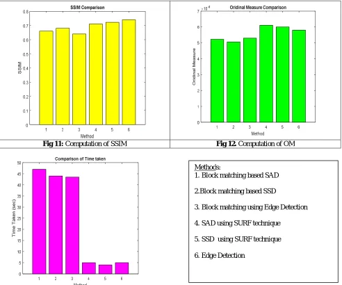
is tabulated in TABLEI and the graphs are plotted. The x axis of the plot indicates different methods used and y axis is the performance metrics used.
Fig 11: Computation of SSIM Fig 12. Computation of OM
Fig. 13 Computation of Time Taken to lapse
V.CONCLUSION
The results obtained show that the accuracy of the disparity map produced using SURF technique is more when compared to the accuracy of the disparity map produced using block matching technique. However the edge detection is subjected to both the techniques, the edges recovered will be almost same comparatively but the advantage is the time lapse to determine object distance is much less in SURF technique.
Methods:
1. Block matching based SAD
2.Block matching based SSD
3. Block matching using Edge Detection
4. SAD using SURF technique
5. SSD using SURF technique
REFERENCES
1. Yong-Jun Chang and Yo-Sung HO, Disparity estimation using edge preserving method, 978-1-4799-8641-5/15/15/$31.00©2015 IEEE. 2. Dang KhanhHoa, Le Dung, NguyuenTienDzung, Efficient determination of disparity map from stereo images with modified sum of absolute
differences (SAD) algorithm, international conference of advanced technologies for communications (ATC-13).
3. D. Chandra Devi, M. Sundaresan, Exhaustive block matching algorithm to estimate disparity between stereo images. 978-9-3805-4421-2/16$31.00©2016 IEEE
4. Raad.H. Thaher, Zaid.K. Hussein Stereo Vision Estimation employing SAD with Canny Edge Detector, International Journal of Computer Applications (0975-8887) Volume 107-No.3, December 2014.
5. Edouard Oyallon, J ulien Rabin, An Analysis of SURF method, Published in Image Processing On Line (IPOL), submitted on 2013-02-12,accepted on 2015-05-30 ISSN 2015-1232 © 2015 IPOL & the authors CC-BY-NC-SA.
6. Christos Georgoulas, Georgios, Ch. Sirakoulis and Ioannis Andreadis, “Real-time Stereo Vision Applications,” Robot Vision, pg. 275-292, First publish March 2010
BIOGRAPHY