ISSN(Online): 2320-9801
ISSN (Print): 2320-9798
I
nternational
J
ournal of
I
nnovative
R
esearch in
C
omputer
and
C
ommunication
E
ngineering
(A High Impact Factor, Monthly, Peer Reviewed Journal)
Website: www.ijircce.com
Vol. 7, Issue 5, May 2019
Load Balancing of Tasks in Cloud Computing
Environment Based on Priority Algorithm
Nidhi Pateriya, Prof. Mahendra Kumar Rai
Research Scholar, Department of Computer Science & Engineering, Shri Ram Institute of Technology - [SRIT], Jabalpur, India
Assistant Professor & Head, Department of Information & Technology, Shri Ram Institute of Technology - [SRIT], Jabalpur, India
ABSTRACT: Cloud computing is a rising technology which is responsible for supplying of computing resources on
the basis of demand, as and when needed. Cloud provides many facilities due to its vast resources such as sharing resources for different purposes. Cloud computing faces many challenges in respect of performance and efficiency. To increase the cloud computing environment's efficiency, Virtual Machines (VM) has been employed for resource provisioning. In this paper, we proposed an algorithm that performs load distribution of workloads among different VM based on priority. This algorithm is proposed in the aim of load balancing of different nodes by considering maximum throughput with minimum execution time. To achieve that, the VM are sorted according to their processing powers and job requests are assigned to VM based on their instruction numbers and priorities. The proposed algorithm is experimented using CloudSim simulator and the results demonstrated that the performance of the algorithm is better than other conventional algorithms.
KEYWORDS: cloud computing, load balancing, round robin algorithm, turnaround time, waiting time, context switch.
I. INTRODUCTION
Cloud Computing, internet-based computing service, provides the different types of cloud services such as servers, storage and application to the resources of the organizations. It plays an important role in IT industries. It has showed the way, how to develop software by providing the flexibility of resources which have been shared between the developers. Cloud computing is not only can provide the services to many users at the same time and also the resources have been reallocated as per user demand. It affords the facility to users that users can access their data from any place in the world. Cloud Computing provides an economic business model that shows how to manage IT resources in various ways [1].In cloud computing environment, Load Balancing is the most important task. Load balancing is the mechanism of distributing of resources in that a way that no overloading has been occurred at any resource and optimal utilization has been performed [2].Every resource works more efficiently which minimizes the response time. The Load Balancer should ensure under and over loading of any resource [3]. In cloud computing environment, it is not very easy to maintain all constrains such as security, reliability and throughput. There are few components which need more attention, Virtual Machine (V.M.) is one of them [4]. Virtual Machine (V.M) is the software platform instate of a physical machine where services are executed like physical machine. It works very efficiently and work like a real machine in which no straight connection to any real hardware has implemented.
ISSN(Online): 2320-9801
ISSN (Print): 2320-9798
I
nternational
J
ournal of
I
nnovative
R
esearch in
C
omputer
and
C
ommunication
E
ngineering
(A High Impact Factor, Monthly, Peer Reviewed Journal)
Website: www.ijircce.com
Vol. 7, Issue 5, May 2019
that no nodes get heavily loaded or lightly loaded. The load balancing has to be performed properly since any one of the nodes is failed that can lead to loss or unavailability of data [8][1].
Depend on implementation method; load balancing algorithm is 2 types [5]. Static Load Balancing Algorithm is current state of the system that don‟t play any role on load balancer‟s decision. Load balancer takes the decision that in which virtual machine the service will be allocated and executed Whereas dynamic load Balancing algorithm depends on the current situation of the machine. The load balancer checks the current load of each available virtual machine then allocates service at suitable and proper virtual machine. In any load balancing algorithm, the load balancer must try to fulfill the following properties like Maximum number of context switches, throughput, CPU utilization, minimum turnaround time, response time and waiting time.
The rest part of the paper is arranged as follows. Section II gives a rough overview of related work. Section III discusses about the new proposed dynamic time quantum priority-based algorithm has been proposed which is suitable for load balancing in cloud computing environment. Section IV experimental results are shown. Finally, in section V the conclusion is discussed.
II. RELATED WORK
The load balancer uses the concept of time slices in basic round robin algorithm. In this method, the execution time is distributed into multiple time slices and each node gets a particular time interval like the concept of time scheduling. Within given time quantum each service request is served by the processor. After completion of each time slice, the next user can request and it comes for processing. If the client‟s service request completes its execution within assigned time quantum or time slice then user would not wait for next round otherwise user has to wait for next round. The basic and primary advantage of this algorithm is that the load balancer allocates the equal time for every service request which ensure fairness.
been defined by sum of maximum burst time and minimum burst time which is divided by 2.In FairRR[7] algorithm they have used the bust time(BT) to calculate the dynamic time quantum(TQ) for every
process which is in ready queue. First, they choose minimum bust time from all the processes and then allocate dynamic TQ to each process where TQ is min BT.
In Priority Based Round Robin algorithm [6] and Intelligent
Time Slice(ITS) has been estimated and allocated the different processing time to each service according to their assigning priority basis. All above methods focus on different measuring parameters of this algorithm. The following parameters are
A. Burst Time (BT)
BT is actually time that is required to complete execution of particular service request.
B. Time Quantum (TQ)
TQ is the given time period for a service to allow to access a VM.
III. IMPLEMENTATION
CLOUDSIM SOFTWARE
CloudSim is a simulation tool that allows Cloud developers to test performance of their provisioning policies in a repeatable and controllable environment free of cost. It helps
ISSN(Online): 2320-9801
ISSN (Print): 2320-9798
I
nternational
J
ournal of
I
nnovative
R
esearch in
C
omputer
and
C
ommunication
E
ngineering
(A High Impact Factor, Monthly, Peer Reviewed Journal)
Website: www.ijircce.com
Vol. 7, Issue 5, May 2019
CloudSim is It is basically a Library for Simulation of Cloud Computing Scenarios. It has some features such as it support for modeling and simulation of large scale Cloud Computing infrastructure, including data centers on a single physical computing node. It provides basic classes for describing data centers, virtual machines applications, users, computational resources, and Policies.
It also supports evaluation of Green IT policies. User can use it as building blocks for simulated Cloud environment and can add new policies for scheduling, load balancing, and new scenarios. It is flexible enough to be used as a library that allows you to write a desired scenario by writing a Java program
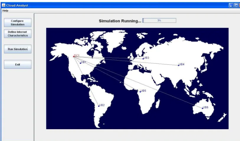
The simulation and analysis of the performance of the three load balancing algorithms are performed using the "Cloud Analyst" tool [5]. It allows the user to run multiple simulations with small parameter changes, and also allows you to customize the location of the users who create the application and the location of the data centers [6]. Let's indicate the terminology of the emulator (Fig. 4):
o Region: in Cloud Analyst, the world is divided into 6 regions that coincide with the 6 major continents in the world;
o User Base: User Base is considered as a single unit, and is used to generate traffic;
o Data Processing Center: brokerage services determine which center should accept and process the request that comes from each user database;
o VmLoadBalancer: it is responsible for distributing the load to the available data center. VmLoadBalancer distributes the load in the data center based on the load balancing policy.
ISSN(Online): 2320-9801
ISSN (Print): 2320-9798
I
nternational
J
ournal of
I
nnovative
R
esearch in
C
omputer
and
C
ommunication
E
ngineering
(A High Impact Factor, Monthly, Peer Reviewed Journal)
Website: www.ijircce.com
Vol. 7, Issue 5, May 2019
Data Center Architecture:
The data center is home to the computational power, storage, and applications necessary to support an enterprise business. The data center infrastructure is central to the IT architecture, from which all content is sourced or passes through. Proper planning of the data center infrastructure design is critical, and performance, resiliency, and scalability need to be carefully considered.
Region Division:
The whole earth is divided into five regions to match with the classification of cloud analyzer. Region divisions and the countries within these regions are as follows:[5]
S.No. Region Countries
1 R0 USA
2 R1 Countries of North America
3 R2 Countries of European union
4 R3 Countries of Asia like china, India
5 R4 Country from Africa
6 R5 Australia
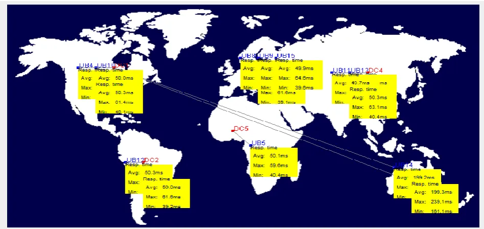
Here the simulation and performance analysis will be done by using the cloud analyst tool, as depicted in Figure 5.1.
ISSN(Online): 2320-9801
ISSN (Print): 2320-9798
I
nternational
J
ournal of
I
nnovative
R
esearch in
C
omputer
and
C
ommunication
E
ngineering
(A High Impact Factor, Monthly, Peer Reviewed Journal)
Website: www.ijircce.com
Vol. 7, Issue 5, May 2019
IV. DATA CENTER NETWORK DESIGN
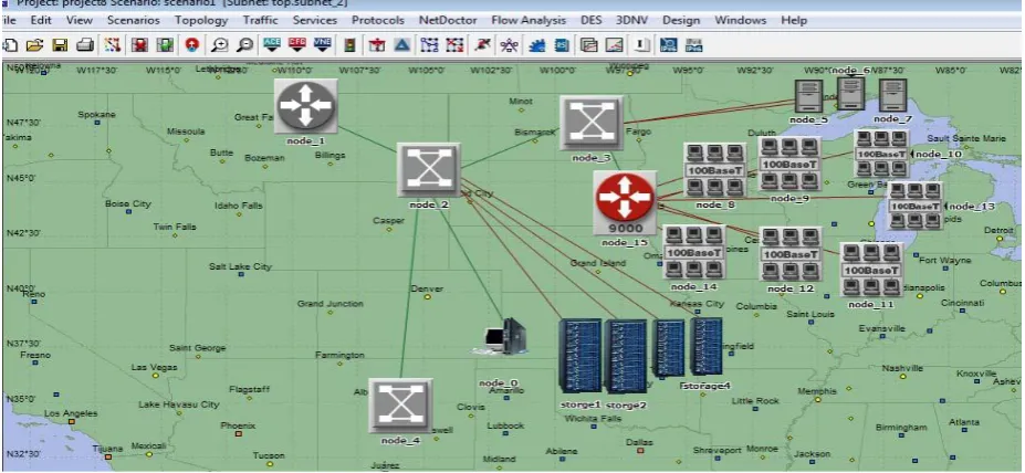
The Design and simulation for performance analysis will be done by using the OPNET simulation software, as shown in Figure 5.2 bellow.
Fig. 5.3: The simulation, design and analysis by using
OPNET
Fig. 5.4 illustrate the design of data-centers subnets, it show that each subnet include storage devices, server, routers and workstations. There are five subnets each of them are about data-center and they connected together by wire line. Each region contains one data-center.
ISSN(Online): 2320-9801
ISSN (Print): 2320-9798
I
nternational
J
ournal of
I
nnovative
R
esearch in
C
omputer
and
C
ommunication
E
ngineering
(A High Impact Factor, Monthly, Peer Reviewed Journal)
Website: www.ijircce.com
Vol. 7, Issue 5, May 2019
by using OPNET Data Center Configuration Parameter: Total 05 data center will be considered for the simulation environment. Architecture of each data centre is given in table (2)
TABLE 3.1 Initial conditions
VM Core units Hours
VM1 2 3
VM2 1 1
VM3 6 6
VM4 3 2
VM5 3 5
VM6 2 2
Here we define VM, VM core units and time. Total capacity of physical machine is 9 unit. Show the matrix, it is initial stage, If VM complete before 3.5 hours than VM is short life job otherwise it is long life job.
In second stage incoming VM1 needs 3 hours time for running the job. here VM1 runs before 3.5 hours so VM1 is TABLE 3.2 Stage:2 of example
PM1
(Total unit= 9)
PM2
(Total unit= 9)
Short life VM1(3 hours)
Long life
Remaining unit 7
short life job. Therefore VM1 store in 1st physical machine and need 2 core unit. So remaining capacity of physical machine is 7 unit.
TABLE 3.3 Stage: 3 of example
PM1
(Total unit= 9)
PM2
(Total unit= 9)
Short life VM1(2 hours)
VM2(1 hours)
Long life
ISSN(Online): 2320-9801
ISSN (Print): 2320-9798
I
nternational
J
ournal of
I
nnovative
R
esearch in
C
omputer
and
C
ommunication
E
ngineering
(A High Impact Factor, Monthly, Peer Reviewed Journal)
Website: www.ijircce.com
Vol. 7, Issue 5, May 2019
In third stage new VM2 is arrive which need 1 hour for run and 1 unit capacity. So our remaining capacity is 6 unit for 1st physical machine.
In table VI, new VM3 is arrive. At the same time VM1 completed 1hour work and VM2 is finish.VM3 require 6 hours and 6 unit capacity. So our remaining unit is 1.
In the fifth stage, remaining hour of VM1 and VM3 is 1 and 5. New VM4 enter with 2 hours and 3 unit. But physical machine 1 is contain only one unit capacity so VM4 place in physical machine 2.
In sixth stage, VM5 is enter with 5 hours and 1 unit capacity. VM5 first check 1st physical machine. PM1 contain remaining capacity of 1 unit. So VM5 place in 1st physical machine. So remaining unit is 0 for PM1.
TABLE 3.4 Stage: 4 of example
PM1
(Total unit= 9)
PM2
(Total unit= 9)
Short life VM1(1 hours)
VM2 is Finish
Long life VM3(6 hours)
Remaining unit 1
TABLE 3.5 Stage: 5 of example
PM1
(Total unit= 9)
PM2
(Total unit= 9)
Short life VM1(1 hours)
VM4(2 hours)
Long life VM3(5 hours)
ISSN(Online): 2320-9801
ISSN (Print): 2320-9798
I
nternational
J
ournal of
I
nnovative
R
esearch in
C
omputer
and
C
ommunication
E
ngineering
(A High Impact Factor, Monthly, Peer Reviewed Journal)
Website: www.ijircce.com
Vol. 7, Issue 5, May 2019
TABLE 3.6 Stage: 6 of example
PM1
(Total unit= 9)
PM2
(Total unit= 9)
Short life VM1 is finish VM4(2 hours)
Long life VM3(4 hours)
VM5(5 hours)
Remaining unit 0 6
TABLE 3.7 Stage: 7 of example
PM1 (Total unit= 9) PM2 (Total unit= 9)
Short life VM1 is finish VM4(2 hours)
VM6(2 hours)
Long life VM3(4 hours)
VM5(5 hours)
Remaining unit 0 4
In next stage, PM1 is full so newly coming VM place in PM2. Show the final condition of example in table IX.
IV. RESULT SYSTEM PERFORMANCE
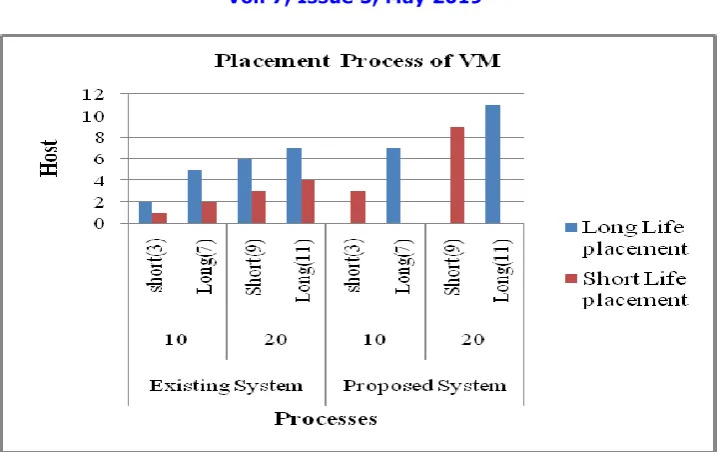
In first graph, we define the placement process of VM. In existing work all short life and long life VM placement is done on same physical machine and in our proposed work, we arrange all short life VMs on same container and long life VM on same container. So our resource utilization is maximizing, show in graph.
ISSN(Online): 2320-9801
ISSN (Print): 2320-9798
I
nternational
J
ournal of
I
nnovative
R
esearch in
C
omputer
and
C
ommunication
E
ngineering
(A High Impact Factor, Monthly, Peer Reviewed Journal)
Website: www.ijircce.com
Vol. 7, Issue 5, May 2019
Fig. 5.0 Placement process of VM
In table 5.1, we define existing placement process. Here all short life and long life VM place in same PM.
Existing system
10 20
Short(3) Long(7) Short(9) Long(11)
Long life placement 2 5 6 7
Short life placement 1 2 3 4
TABLE 5.1 Existing placement process
Table 5.2 defined our proposed strategy. Where we create short life and long life container.
Proposed system
10 20
Short(3) Long(7) Short(9) Long(11)
Long life placement 0 7 0 11
Short life placement 3 0 9 0
ISSN(Online): 2320-9801
ISSN (Print): 2320-9798
I
nternational
J
ournal of
I
nnovative
R
esearch in
C
omputer
and
C
ommunication
E
ngineering
(A High Impact Factor, Monthly, Peer Reviewed Journal)
Website: www.ijircce.com
Vol. 7, Issue 5, May 2019
Table 5.3 shows the placement of short life job according to load in existing system and proposed system. TABLE 5.3. Placement of short life job
Placement of short life VM
Existing system Proposed system
0 to 2 7 7
2 to 4 3 3
4 to 6 8 6
6 to 8 7 0
8 to 10 5 0
In fig. 5.2 we define utilization of resource or PM. According to the Optimization function.
ISSN(Online): 2320-9801
ISSN (Print): 2320-9798
I
nternational
J
ournal of
I
nnovative
R
esearch in
C
omputer
and
C
ommunication
E
ngineering
(A High Impact Factor, Monthly, Peer Reviewed Journal)
Website: www.ijircce.com
Vol. 7, Issue 5, May 2019
Existing System Proposed System Nearest
value to the 1
Nearest value to the 0
Nearest value to the 1
Nearest value to the 0
20 6 14 9 11
30 13 17 18 12
40 18 22 21 19
50 21 29 31 19
60 25 35 38 22
V. CONCLUSION AND FUTURE WORK
After doing rigorous survey on various issues in resource utilization, we found that load balancing, VM placement and fragmentation are the greatest issue in cloud computing. So we propose dynamic priority based spill over technique and add the concept of short life/long life container for solving the fragmentation issue. Our architecture maximize the resource utilization also we minimize fragmentation issue with using short life/long life container at physical machine in our architecture.
REFERENCES
[1] Amandeep, „„Analysis of Load Balancing Techniques in Cloud Computing‟‟, International Journal of Computers & Technology, vol. 4, no.2, pp.2277- 3061, March-April, 2013.(references)
[2] Angona Sarker,Ali Newaz Bahar,SM Shamim, "A Review on Mobile Cloud Computing", International Journal of Computer Applications (0975 – 8887)
[3] Aarti Singha, Dimple Junejab, Manisha Malhotraa,"Autonomous Agent Based Load Balancing Algorithm in Cloud Computing"- International Conference on Advanced Computing Technologies and Applications (ICACTA- 2015)
[4] B.Subramani, „„A New Approach For Load Balancing In Cloud Computing‟‟, IEEE ,vol.2, pp. 1636-16405, May 2013.
[5] Buyya, Rajkumar. "Market-oriented cloud computing: Vision, hype, and reality of delivering computing as the 5th utility". In Proceedings of the 2009 9th IEEE/ACM.
[6] Geethu Gopinath P , Shriram K Vasudevan,"An in- depth analysis and study of Load balancing techniques in the cloud computing environment"-. 2nd International Symposium on Big Data and Cloud Computing (ISBCC‟15).
[7] Ruhi Gupta. "Review on Existing Load Balancing Techniques of Cloud Computing." International Journal of Advanced Research in Computer Science and Software Engineering Volume 4, Issue 2, February 2014.
[8] Jinhua Hu," A Scheduling Strategy on Load Balancing of Virtual Machine Resources in Cloud Computing Environment", 3rd International Symposium on Parallel Architectures, Algorithms and Programming 978-0-7695- 4312-3/10 © 2010 IEEE (published)
[9] Jayant Baliga, Robert W. A. Ayre, Kerry Hinton, and Rodney S.1Tucker, Fellow IEEE, “Green Cloud Computing: Balancing Energy in Processing, Storage, and Transport”.
[10] S. Kapoor, and C. Dabas, Cluster based load balancing in cloud computing, Proc. Eighth International Conference in Contemporary Computing (IC3), 2015, 76-81.
[11] Klaithem Al Nuaimi," A Survey of Load Balancing in Cloud Computing: Challenges and Algorithms", 2012 IEEE Second Symposium on Network Cloud
ISSN(Online): 2320-9801
ISSN (Print): 2320-9798
I
nternational
J
ournal of
I
nnovative
R
esearch in
C
omputer
and
C
ommunication
E
ngineering
(A High Impact Factor, Monthly, Peer Reviewed Journal)
Website: www.ijircce.com
Vol. 7, Issue 5, May 2019
[12] Mohit and Jitender Kumar, International Journal of Advanced Research in Computer Science and Software Engineering ,"A Survey of Existing Load Balancing Algorithms in Cloud Computing".
[13] S.Mohinder, R,Ramesh, D.Powar, „„Analysis of Load Balancers in Cloud Computing‟‟, International Academy of Science, Engineering & Technology, vol.2, May 2013.
[14] Poulami Dalapati1, G. Sahoo,"Green Solution for Cloud Computing with Load Balancing and Power Consumption Management"- International Journal of Emerging Technology and Advanced Engineering,Vol3:2013
[15] Saurabh Kumar Garg and Rajkumar Buyya, “ Green Cloud computing and Environmental Sustainability”.(references)
[16] Sidhu A, S.Kinger, “Analysis of Load Balancing techniques in Cloud Computing”, Council for innovative research international Journal of Computer & Technology, vol.4, March-April 2013.
[17] Sumalatha M.R, C. Selvakumar, T. Priya, R. T. Azariah, and P. M. Manohar, "CLBC-Cost effective load balanced resource allocation for partitioned cloud system", Proc. International Conference on Recent Trends in Information Technology (ICRTIT), 2014, 1-5.
[18] The Amazon Elastic Compute Cloud (Amazon EC2), http://aws.amazon.com/ec2/
[19] Yilin Lu," A Hybrid Dynamic Load Balancing Approach for Cloud Storage", 2012 International Conference on Industrial Control and Electronics Engineering 978-0-7695-4792-3/12 © 2012 IEEE.