University of Windsor University of Windsor
Scholarship at UWindsor
Scholarship at UWindsor
Electronic Theses and Dissertations Theses, Dissertations, and Major Papers
1-8-2016
Attack-Aware Routing and Wavelength Assignment of Scheduled
Attack-Aware Routing and Wavelength Assignment of Scheduled
Lightpath Demands
Lightpath Demands
Hongbo Zhao
University of Windsor
Follow this and additional works at: https://scholar.uwindsor.ca/etd
Recommended Citation Recommended Citation
Zhao, Hongbo, "Attack-Aware Routing and Wavelength Assignment of Scheduled Lightpath Demands" (2016). Electronic Theses and Dissertations. 5681.
https://scholar.uwindsor.ca/etd/5681
This online database contains the full-text of PhD dissertations and Masters’ theses of University of Windsor students from 1954 forward. These documents are made available for personal study and research purposes only, in accordance with the Canadian Copyright Act and the Creative Commons license—CC BY-NC-ND (Attribution, Non-Commercial, No Derivative Works). Under this license, works must always be attributed to the copyright holder (original author), cannot be used for any commercial purposes, and may not be altered. Any other use would require the permission of the copyright holder. Students may inquire about withdrawing their dissertation and/or thesis from this database. For additional inquiries, please contact the repository administrator via email
Attack-Aware Routing and Wavelength
Assignment of Scheduled Lightpath
Demands
By
Hongbo Zhao
A Thesis
Submitted to the Faculty of Graduate Studies through the School of Computer Science in Partial Fulfillment of the Requirements for
the Degree of Master of Science at the University of Windsor
Windsor, Ontario, Canada
2016
c
Attack-Aware Routing and Wavelength Assignment of Scheduled Lightpath
Demands
by
Hongbo Zhao
APPROVED BY:
Dr. Esam Abdel-Raheem
Department of Electrical and ComputerEngineering
Dr. Dan Wu
School of Computer Science
Dr. Arunita Jaekel School of Computer Science
DECLARATION OF ORIGINALITY
I hereby certify that I am the sole author of this thesis and that no part of this
thesis has been published or submitted for publication.
I certify that, to the best of my knowledge, my thesis does not infringe upon
anyones copyright nor violate any proprietary rights and that any ideas, techniques, quotations, or any other material from the work of other people included in my
thesis, published or otherwise, are fully acknowledged in accordance with the standard referencing practices. Furthermore, to the extent that I have included copyrighted
material that surpasses the bounds of fair dealing within the meaning of the Canada Copyright Act, I certify that I have obtained a written permission from the copyright
owner(s) to include such material(s) in my thesis and have included copies of such copyright clearances to my appendix.
I declare that this is a true copy of my thesis, including any final revisions, as approved by my thesis committee and the Graduate Studies office, and that this thesis
ABSTRACT
In Transparent Optical Networks, traffic is carried over lightpaths, creating a vir-tual topology over the physical connections of optical fibers. Due to the increasingly
high data rates and the vulnerabilities related to the transparency of optical network, security issues in transparent wavelength division multiplexing (WDM) optical
net-works have become of great significance to network managers. In this thesis, we intro-duce some basic concepts of transparent optical network, the types and circumstances
of physical-layer attacks and analysis of related work at first. In addition, based on the previous researches, we present a novel approach and several new objective
cri-terions for the problem of attack-aware routing and wavelength assignment. Integer Linear Programming (ILP) formulation is used to solve the routing sub-problem with
the objective to minimize the disruption of physical-layer attack as well as to opti-mize Routing and Wavelength Assignment (RWA) of scheduled transparent optical
DEDICATION
To my Loving Family:
Father: Jinrong Zhao
ACKNOWLEDGEMENTS
I would love to express my deepest gratitude to my master supervisor, Dr. Arunita
Jaekel, for her teaching and support throughout my graduate studies. She provides me with great ideas about thesis topic, simulation cases and at the same time spends
much time instructing me on proposal, program, testing, thesis writing and defense. Also, I want to appreciate the members of my M.Sc. thesis committee, internal
reader Dr. Dan Wu and external reader Dr. Esam Abdel-Raheem for their profes-sional assistance and guidance on my research and thesis.
TABLE OF CONTENTS
DECLARATION OF ORIGINALITY III
ABSTRACT IV
DEDICATION V
ACKNOWLEDGEMENTS VI
LIST OF TABLES X
LIST OF FIGURES XI
I Introduction 1
1.1 Overview . . . 1
1.1.1 Advantages of Optical Network . . . 2
1.1.2 Wavelength-Division Multiplexing (WDM) . . . 2
1.1.3 Opaque & Transparent Optical Network . . . 3
1.1.4 Routing and Wavelength Assignment (RWA) . . . . 4
1.2 Motivation . . . 5
1.3 Problem Statement . . . 6
1.4 Solution Outline . . . 7
1.5 Organization of Thesis . . . 7
TABLE OF CONTENTS
2.1.1 Differences between Attack and Fault . . . 9
2.1.2 Attack Types in All-Optical Networks . . . 10
2.2 Objectives for Attack-aware RWA Problem . . . 14
2.2.1 Lightpath Attack Radius (maxLAR) . . . 14
2.2.2 In-band Crosstalk Attack Radius (maxIAR) . . . 17
2.3 Review of Related Work . . . 19
2.4 Summary of Referenced Paper . . . 22
III Security-aware Scheduled RWA 24 3.1 Introduction . . . 24
3.2 Problem Definition . . . 25
3.2.1 LAR and IAR in Scheduled Networks . . . 26
3.3 Proposed ILP Formulation . . . 28
3.3.1 ILP Formulation : ILP AR1 . . . 28
3.4 Alternative objective functions . . . 36
3.4.1 ILP Formulation : ILP AR2 . . . 36
3.4.2 ILP Formulation : ILP SUM AR2 . . . 36
3.4.3 ILP Formulation : ILP SUM AR1 . . . 37
3.4.4 ILP Formulation : ILP SPATH . . . 37
3.4.5 Summary of ILP Objectives . . . 38
IV Experimental Results 39 4.1 Experimental Setup . . . 39
4.1.1 Physical Topologies . . . 40
4.1.2 Lightpath Demand Sets . . . 40
4.2 Results of Experiment . . . 42
TABLE OF CONTENTS
V Conclusion and Future Work 52
5.1 Conclusion . . . 52 5.2 Future Work . . . 53
References 53
LIST OF TABLES
1.1 an Example of Scheduled Demand Set . . . 5
2.1 an Example of Scheduled Demand Set[9] . . . . 10
2.2 Lightpath Attack Radius of each lightpath in Fig 2.7 (a) . . . 16
2.3 Lightpath Attack Radius of each lightpath in Fig 2.7 (b) . . . 16
2.4 In-band Attack Radius of each lightpath in Fig 2.8 (a) . . . 18
2.5 In-band Attack Radius of each lightpath in Fig 2.8 (b) . . . 19
2.6 Summary of Referenced Papers . . . 22
3.1 the value of LAR of each lightpath during each interval . . . 27
3.2 the value of IAR of each lightpath during each interval . . . 27
3.3 Proposed ILP formulations and objectives . . . 38
4.1 Comparison of Objective 1 for 20 Demands . . . 43
4.2 Comparison of Objective 2 for 20 Demands . . . 43
4.3 Comparison of Objective 3 for 20 Demands . . . 44
4.4 Comparison of Objective 4 for 20 Demands . . . 44
4.5 Comparison of Objective 1 values with different demand sizes . . . . 46
4.6 Comparison of Objective 2 values with different demand sizes . . . . 47
4.7 Comparison of Objective 3 values with different demand sizes . . . . 47
4.8 Comparison of Objective 4 values with different demand sizes . . . . 48
4.9 Comparison of average path lengths for LDO traffic . . . 50
4.10 Comparison of average path lengths for MDO traffic . . . 50
LIST OF FIGURES
1.1 Optical Fiber Cable & Metal Cable[12] . . . 2
1.2 WDM Components [13] . . . . 2
1.3 Opaque Optical Network Topology [14] . . . 3
1.4 Transparent Optical Network Topology [14] . . . . 3
1.5 a wavelength-routed optical network with lightpath connections[17] . 4 2.1 the Seven Layers of OSI . . . 8
2.2 Rerouting Connections can solve link failure . . . 10
2.3 Gain Competition in amplifiers . . . 11
2.4 Simulation diagram of gain competition attack . . . 12
2.5 Inter-channel Crosstalk . . . 12
2.6 In-band crosstalk attack propagation[2] . . . 13
2.7 maxLAR of two RWA schemes with the same lightpath demands . . 15
2.8 maxIAR of two RWA schemes with the same lightpath demands . . . 18
2.9 an example of RWA scheme for P-CAR . . . 20
2.10 A New Detection Method[21] . . . 21
3.1 an example of physical network topology . . . 25
3.2 lightpath demands and intervals for each demand . . . 25
3.3 an example of RWA and interval assignment . . . 26
LIST OF FIGURES
4.4 Results of Objective 4 for MDO with 20 demands . . . 45
4.5 Results of Objective 4 for HDO with 20 demands . . . 46 4.6 Variation of Objective 4 with demand size in 14-node network for LDO 48
CHAPTER I
Introduction
1.1
Overview
Optical networks constitute a telecommunication network architecture on the
ba-sis of optical fibers, which uses signals encoded onto light to transmit information among various nodes[13]. Optical communication provides large capacity over long
distances, high reliability transmission, interconnection and management for multi-node networks. Optical networks rely on a series of optical components, e.g. optical
amplifiers, lasers or LEDs, multiplexer, demultiplexer, optical switch, etc. and wave-length division multiplexing (WDM) technology, In recent years, optical network has
emerged to replace traditional metal communication network and is becoming more and more widely used all over the world.
However, security issues of optical network has attracted great attention. Due to the high data rates and the vulnerabilities associated with transparency,
physical-layer attacks caused by high-powered jamming signal can seriously degrade network performance, lead to loss of user data and must be dealt with efficiently[2]. How
to well detect and localize the attack at the lowest possible cost has become a hot issue. In this thesis, we proposed a new objective criterion for security-aware routing
and wavelength assignment (RWA) problem of scheduled network and formulate the routing sub-problem as an integer linear program (ILP). The intention is to minimize
I. INTRODUCTION
1.1.1 Advantages of Optical Network
Optical network uses glass (or plastic) threads (fibers) to transmit data. As shown in Fig. 1.1, a fiber optic cable consists of a bundle of glass threads, each of which is
capable of transmitting messages modulated onto light waves[12].
In comparison with traditional metal communication lines, fiber optics have
sev-eral advantages:
Fig. 1.1: Optical Fiber Cable & Metal Cable [12]
• Fiber optic cables are less susceptible than metal cables to interference.
• Fiber optic cables are much thinner and lighter than metal wires.
• Data can be transmitted digitally.
1.1.2 Wavelength-Division Multiplexing (WDM)
Fig. 1.2: WDM Components [13]
In fiber-optic communications,wavelength-division multiplexing(WDM) is a
I. INTRODUCTION
using different wavelengths of laser light[22]. As demonstrated in Fig. 1.2, a WDM
system uses a multiplexer at the transmitter to join the several signals together and a demultiplexer at the receiver to split them apart. The use of WDM makes it possible
that two or more optical signals with different wavelengths can transmit information on the same optical cable, which reduces physical and manufacturing complexity and
boosts the reliability of the system. In addition, it can be fast recovered when faults
or attacks occur.
1.1.3 Opaque & Transparent Optical Network
According to whether or not the transmitted signal undergoes an optical to electronic to optical (OEO) conversion at different places in the network, the optical network
can be mainly divided into (i) Opaque Network and (ii) Transparent Network.
Fig. 1.3: Opaque Optical Network Topology[14]
As described from Fig 1.3, it is a network topology of opaque optical network and the OEO conversion occurs in the opaque switch.
Fig. 1.4: Transparent Optical Network Topology[14]
Fig 1.4 demonstrates a transparent optical network topology, from this graph
we can see that there are no WDM transponders in transparent optical network. The lightpath signals remain in an optical format from the source to the destination
I. INTRODUCTION
1.1.4 Routing and Wavelength Assignment (RWA)
Given a set of connections, the problem of setting up lightpaths by routing and assigning a wavelength to each connection is called the Routing and Wavelength
Assignment (RWA) problem. That is to say, in setting up a lightpath, a route must be selected and a wavelength must be assigned to the lightpath. If no wavelength is
available for this lightpath on the selected route, the connection request is blocked. Also, the RWA problem must be subject to the following two constrains:
• Wavelength Continuity Constraint: If no wavelength converters are available,
the same wavelength must be assigned along the entire route of a lightpath.
• Wavelength Clash Constraint: Any two lightpaths sharing a common fiber link
cannot be assigned the same wavelength.
Fig. 1.5: a wavelength-routed optical network with lightpath connections [17]
Fig 1.5 illustrates a wavelength-routed network, where lightpaths have been set
up between pairs of nodes on different wavelengths. We can see from the diagram, although two or more lightpath share the same optical link, they have to be provided
different wavelength. Typically, connection requests (demands) may be of three types: static, scheduled and dynamic[23].
• Static Traffic: The demands are allocated for the entire duration of the network,
I. INTRODUCTION
• Dynamic Traffic: The start times and durations of demands are generated
ran-domly based on certain traffic distributions or probability
• Scheduled Traffic: In scheduled traffic, time dimension of demands should be
explicitly considered, which means we need to specify the specific time intervals. As seen from Table 1.1, there are three demands, r1, r2 and r3. Each demand is
represented by a tuple (s,d,ts,te) where s and d are the source and destination node, ts and te are the starting time and ending time.
TABLE 1.1: an Example of Scheduled Demand Set
Demands s d ts te
r1 2 9 05:00 09:20 r2 5 2 07:00 12:40
r3 3 7 08:00 14:00
1.2
Motivation
Along with the development and wide application of transparent wavelength divi-sion multiplexing (WDM) optical networks, security issues and physical-layer attack
management have become increasingly important to the network manager. The major advantages of transparent optical networks depend on their character of transparency,
which allows high-speed connections without undergoing optical to electronical to op-tical (OEO) conversion at intermediate nodes. However, it is also the transparency
that leads to vulnerabilities in security and enhances the difficulties in detecting and localizing attacks because monitoring must be performed in the optical domain[3]. In
addition, detecting techniques aiming at detecting and localizing attacks relied on information from specialized optical monitoring equipment can be quite expensive.
In general the more reliable performance of the network required, the more resources are needed and thus the cost of the security equipment is higher[9].
In this thesis, we are aiming at minimize the potential damage of various attacks on the optical network without the need for specialized equipment. Accordingly, the
I. INTRODUCTION
when solving the RWA problem. Integer Linear Programming (ILP) is a
mathemat-ical optimization program which can be used to solve the routing sub-problem with the objective to minimize the crosstalk attack radius and in-band attack radius in
scheduled optical network. In summary, our approach relies on optimally arranging the set of lightpaths to minimize the possible disruptions caused by various attack
scenarios to reduce the number of lightpaths attacked, which can not only reduce the
potential network service disruption but also make failure detection and localization algorithms be faster since they only need to search fewer potential lightpaths[4].
1.3
Problem Statement
In this thesis, we propose a novel algorithm which uses integer linear program (ILP) to address the security-aware routing and wavelength assignment problem in scheduled
transparent WDM optical network. Given is a physical network which includes nodes
and links and a virtual topology, i.e. a set of scheduled lightpath demands. The phys-ical edges are assumed to be bidirectional, each representing a pair of optphys-ical fibers.
The RWA problem which searches for physical paths corresponding to lightpath re-quests should be subject to the wavelength continuity constraints and wavelength
clash constrains. We set enough wavelengths (channels) to accommodate the set of lightpaths. We also select random time intervals between 1 and 24, during which
each lightpath request is acquired. In order to better measure physical-layer attack, we introduce two concepts, i.e. Lightpath Attack Radius (LAR) and In-band Attack
Radius (IAR), which will be presented in detail in the next chapter. The approach to optical networks security is aimed at minimizing the potential damage caused by
sev-eral major physical-layer attacks including gain competition, inter-channel crosstalk attack and in-band crosstalk attack[2]. Several simulation scenarios (including
differ-ent number of nodes, lightpath demands, intervals, etc.) will be created to acquire the objective values. Then we compare them with the cases which are also with the
objective of minimizing lightpath congestion (i.e. shortest path of each lightpath re-quest) but only not considering the security, so that we can prove the advantages of
I. INTRODUCTION
network.
1.4
Solution Outline
In this thesis, we present optimal Integer Linear Program (ILP) formulations for
solving security-aware scheduled RWA problems. IBM ILOG CPLEX Optimization software is used to solve the formulations. The major contribution of this thesis are:
• A novel algorithm and ILP formulations to address the security-aware RWA
Problem for scheduled traffic which has not been done.
• Several objectives that comprehensively take both lightpath attack radius (LAR)
and in-band attack radius (IAR) into consideration.
• Comparison of the security performance (anti-attack capacities) between our
approach and traditional RWA approach without considering security for vari-ous lightpath demands and different scales of network
1.5
Organization of Thesis
The remainder of the thesis is organized as follows: Chapter 2 presents the necessary introductions of some important concepts such as physical layer attacks, differences
between network faults and attacks and the literature review of previous research associated with network attack detection and localization, security-aware RWA
prob-lem, etc. In Chapter 3, we propose our algorithm and describe the details about ILP formulations. Chapter 4 presents the simulation results that we carry out, analysis
CHAPTER II
Review of Related Work
2.1
Fault and Attack Management
The physical layer (layer 1) sits at the bottom of the Open System Interconnect (OSI)
model (As shown in Fig. 2.1), which is designed to transmit bit streams through electric signals, lights or radio transmissions.
Fig. 2.1: the Seven Layers of OSI
Security issues due to transparency in optical network components is a major
challenges for network management[3]. The thesis titled Fault and Attack Manage-ment in All-Optical Networks[4] covers management issues with particular emphasis
on complications due to the unique characteristics and behaviors of transparent net-work components. In addition, an algorithm is also presented for multiple attack
II. REVIEW OF RELATED WORK
There are several kinds of attacks, including fiber cuts, power jamming (amplifier
attack), crosstalk attack (switch node attack) and correlated jamming (tapping at-tack), etc[20].Among them, some can be seen as a kind of optical component fault, such
as fiber attack. Others, like crosstalk attack, can affect lightpaths that traverse the same link or node with the attack connections. Crosstalk attack has higher damage
capabilities, which our approach mainly focuses on.
2.1.1 Differences between Attack and Fault
In general, there are three main differences between an attack and a fault.
• An attack appears and disappears sporadically in the network due to attack
signal injection, while a fault occurs usually because of physical natural fatigue and aging of optical devices and components, so it happens slower than an
attack.
• Attacks may trigger multiple erroneous and undesirable alarms due to their
characteristic of propagation. For example, when a lightpath is being attacked, it can in turn attack other lightpaths with which it shares the same physical
links or switches. But faults can only lead to single alarm, it will not affect other lightpaths.
• For fault recovery, rerouting of traffic channels can solve all resulting problems.
However, the same approach cannot solve all resulting problems of an attack.
As describes in Fig 2.2, when the link (2,3) fails, rerouting Primary connection can solve this problem (use Backup lightpath). If an attack signal is injected at
Node 1 and we still treat such attack as a component fault and reroute Primary connection to Backup, we can see this method cannot solve the problem, because
II. REVIEW OF RELATED WORK
Fig. 2.2: Rerouting Connections can solve link failure
2.1.2 Attack Types in All-Optical Networks
All-Optical Networks provide transparency capabilities, allowing routing and switch-ing of traffic without any modification or examination of signals in the network [4].
Admittedly, transparency character has many advantages in supporting high data rate communications, it also brings new challenges that not exist in traditional networks.
Attacks can be considered from different viewpoints. From an attackers perspective, attacks can be widely divided into six areas: traffic analysis, eavesdropping, data
delay, service denial, QoS degradation and spoofing [18]. Because some of these areas have similar characters, the attacks can also be grouped into two main categories, i.e.
service disruption and eavesdropping.
TABLE 2.1: an Example of Scheduled Demand Set[9]
Attack Type Attack Method Component
Service Disruption
In-band jamming power Fiber Out-of-band jamming power Fiber
Intentional Crosstalk
Splitter Filter Switch Gain Competition Amplifier
Eavesdropping Unauthorized Observation
II. REVIEW OF RELATED WORK
As it describes in the Table 2.1, there are various physical-layer attacks that can
happen in different components of TONs. Details about attack methods will be presented below.
Gain Competition
In order to implement an attack, the attacker needs to gain access to the network.
For example, to commit an in-band or out-of-band jamming attack, the attacker can take advantage of the specific characteristics of optical component such as optical
amplifiers and cause gain competition attack[4].
Fig. 2.3: Gain Competition in amplifiers
Fig 2.3 depicts the Gain Competition in an optical amplifier. The attacker injects
a high powered signal at wavelengthλ1 (usually 20-30dB larger than user signal) into a transparent optical network. When they traverse an amplifier, because the amplifier cannot distinguish between attack signals and legitimate network signals, the attack
signal can acquire more energy and additionally increase its power, which leads to the user signal power loss(the supply of gain is finite in amplifier). The scenario of power
robbery in amplifier is known as a gain competition attack. As a result, channel
II. REVIEW OF RELATED WORK
Fig. 2.4: Simulation diagram of gain competition attack
In the year 2010, Furdek et al. [19]verify the gain competition attack arise by high power signal injected in Erbium Doped Fiber Amplifier (EDFA). EDFA is optical
amplifier that use a doped optical fiber as a gain medium to amplify an optical signal. As described in Fig 2.4, the frequency of attack signal is 192.1 THz and the
user signal are 192.3, 192.5, 192.7, 192.9, 193.3, 193.5 THz. When the power of attack signal is 10dB larger than user signal, the gain of user signal starts to decrease. The
more increase in the power of attack signal, the more decrease in the gain of user signal.
Inter-channel Crosstalk Attack
Moreover, long distance transformation and high-power signals injection may
re-sult in another attack called Inter-channel Crosstalk[3].
II. REVIEW OF RELATED WORK
Fig 2.5 shows a high-power jamming signal, which uses a different wavelength from
user signal, injected on a link. The jamming signal is able to disrupt the lightpath it is injected on and the other lightpaths with which it shares the common links.
In-band (Intra-channel) Crosstalk Attack Propagation
Marija Furdek et al. also propose a type of attack, which is similar to in-band
crosstalk attack introduced above, called in-band crosstalk attack propagation[2]. The attack signal may not only affect connections traversing common switches, but also
if enough power is transferred to the affected connection, these connections may also acquire attack abilities themselves[2]. That is to say, the attack can propagate to other
lightpaths through the network and disrupt other legitimate lightpaths far beyond the original attacker [20].
Fig. 2.6: In-band crosstalk attack propagation[2]
Fig 2.6 displays a diagram about in-band crosstalk attack propagation. The attack
signal is injected into the network at switch a. First, it will attack User 1 ’s signal at their common switch a. Then, the signal of legitimate User 1 acquires the attack
power and it attacks User 2 at switch b. Finally, the User 2 who also acquires the attack power from user 1 disrupts User 3 at their common switch c. From this example
II. REVIEW OF RELATED WORK
Eavesdropping
Eavesdropping attack is a realization of unauthorized observation [21], which may happen at several points in the network. Among them, two eavesdropping examples
require more attention. One example comes from component crosstalk: the demulti-plexer is an important component in wavelength division multiplexing (WDM) optical
network which is used to split wavelength received from a single fiber onto separated physical paths. The crosstalk level of demultiplexer is between 0.03% to 1.0%.
How-ever, it is just because of the low ratio of crosstalk level, a little of each wavelength leaks onto the wrong path. If attackers detect the leaked signal and it is very likely
that some of data from the stream can be recovered. The other example of eavesdrop-ping is relevant to the optical amplifier. When signals passing through the amplifier,
they will undergo a slight amplitude modulation on the basis of the presence or ab-sence of signal on adjacent channels [21]. Due to the leak of signal, the attacker may
recover some intended signal on an adjacent channel.
2.2
Objectives for Attack-aware RWA Problem
The attack-aware routing and wavelength assignment (RWA) is aimed at minimizing
the potential damage caused by physical-layer attacks. We are trying to achieve the
prevention measures through careful network planning. In other words, by solving the RWA problem, we try to reduce vulnerabilities to attacks without the requirement
of specific network monitoring components. So, proper objectives which are able to estimate the impact of attack can definitely be an important part in RWA problem
solving.
2.2.1 Lightpath Attack Radius (maxLAR)
In order to better estimate the influence of inter-channel crosstalk attack, an objective
criterion for the RWA problem is maximum Lightpath Attack Radius (maxLAR)[3]. Lightpath Attack Radius (LAR) is defined for every specific lightpath to describe if
II. REVIEW OF RELATED WORK
(on links). However, maxLAR is aimed at the whole network, which is defined as the
number of legitimate data lightpaths any one jamming signal can attack (on links). In other words, maxLAR describes the maximum number of lightpaths (including
itself) any one lightpath shares a common directed physical link with. What is more, there is a relevant concept called Lightpath Attack Group (LAG). It depicts the set
of legitimate lightpaths which are probably attacked by the lightpath that is injected
jamming signal.
Moreover, in wavelength-convertible networks, the concept of network congestion
is the same as the number of wavelength used. As defined, maxLAR is also the upper bound of network congestion as well as the number of wavelengths actually required.
By minimizing this value, we can not only reduce the threat of physical-layer attack, but also decrease the worst case of congestion.
Fig. 2.7: maxLAR of two RWA schemes with the same lightpath demands
Fig 2.7 displays two RWA schemes with the same network topology, wavelength
assignment and lightpath requests. According to Fig 2.7 (a), the the set of lightpath attack group (LAG) and the value of lightpath attack radius (LAR) for each lightpath
II. REVIEW OF RELATED WORK
TABLE 2.2: Lightpath Attack Radius of each lightpath in Fig 2.7 (a)
LP1 LP2 LP3 LP4 LP5
LAG {LP1} {LP2,LP4} {LP3,LP4} {LP2,LP3,LP4,LP5} {LP4,LP5}
LAR 1 2 2 4 2
Specifically, for example, the lightpath attack radius of Lightpath 1 is 1, because it does not share any physical link with other lightpath, which means if the attack
signal being injected in LP1, it can only interfere LP1 itself. Similarly, for Lightpath 4 (LP4) in the topology, due to the fact that it shares the link 1-2 with LP5, link 2-4
with LP2 and link 4-6 with LP3, the value of LAR for LP4 is 4, which represents if LP4 is attacked, except itself, LP2, LP3 and LP5 will also be disrupted because they
share at least one common link with LP4. According to the data of Table 2.2, the maxLAR of the network topology Fig 2.7 (a) is
maxLAR =LARLP4 = 4
In comparison with Fig 2.7 (a), the only difference of Fig 2.7 (b) is the lightpath route of LP4. In Fig 2.7 (a), LP4 traverses links 1-2, 2-4 and 4-6 while in Fig 2.7 (b)
the route is changed to 1-3, 3-5 and 5-6. So, the corresponding value of LAR for each lightpath may be different.
TABLE 2.3: Lightpath Attack Radius of each lightpath in Fig 2.7 (b)
LP1 LP2 LP3 LP4 LP5
LAG {LP1,LP4} {LP2} {LP3} {LP1,LP4} {LP5}
LAR 2 1 1 2 1
We can see from Table 2.3, LP1 only shares the same link (3-5) with LP4 and
vise versa, so the values of LAR for LP1 and LP4 are both 1+1=2 for this network topology. In addition, the values of LAR of LP2, LP3 and LP5 are all equal to 1
II. REVIEW OF RELATED WORK
of Fig 2.7 (b) is:
maxLAR=LARLP1 =LARLP4 = 2
Please note that the value of maxLAR can represent the degree of disruption by
physical attack. In this example, maxLAR of Fig 2.7 (a) is 4 but the value is 2 in Fig 2.7 (b), which means a jamming signal injected on any legitimate lightpath could
disrupt at most 4 lightpaths if the lightpath routes arranged the same as Fig 2.7 (a), however it can only disrupt at most 2 lightpaths in Fig 2.7 (b). From the example
above, we can come to the conclusion that the value of maxLAR is related to the route of lightpaths. That is to say, it is reasonable to minimize the potential attack
threat of inter-channel crosstalk by rerouting the lightpaths.
2.2.2 In-band Crosstalk Attack Radius (maxIAR)
In-band crosstalk attack radius is also defined as a measure to estimate the impact of
in-band crosstalk attack. In length-selective switches, attack signals can attack other lightpaths transmitted on the same wavelength with which they share at least one
common switch. That is to say, in-band crosstalk attack has two characteristics: (1) Lightpaths which are on the same wavelength can be attacked; (2) it generally
hap-pened in switches including the source and destination nodes of a lightpath. Similar to maxLAR, there are also In-band Attack Radius (IAR) and In-band Attack Group
(IAG) defined aiming at each lightpath. IAG describes the set of lightpaths with which one specific lightpath shares the common switch and transmitted on the same
II. REVIEW OF RELATED WORK
Fig. 2.8: maxIAR of two RWA schemes with the same lightpath demands
As demonstrated in Fig 2.8, two RWA schemes are of the same network topology, channel assignment and lightpath demands. However, the lightpath route of LP2 and
LP4 are different. In Fig 2.8 (a), LP2 is routed via nodes 2-4-5, LP4 is routed via nodes 1-2-4-6. In Fig 2.8 (b), LP2 is routed via nodes 2-3-5, whereas LP4 is routed
via nodes 1-3-5-6.
TABLE 2.4: In-band Attack Radius of each lightpath in Fig 2.8 (a)
LP1 LP2 LP3 LP4 LP5
IAG {LP1,LP2,LP5} {LP1,LP2,LP3,LP5} {LP2,LP3} {LP4} {LP1,LP2,LP5}
IAR 3 4 2 1 3
Table 2.4 presents the value of IAR for each lightpath. If a high-powered signal
is injected on lightpath 1 (LP1) at its source node 1, the attacker can potentially disrupt LP5 in their common node (switch) 1 and LP2 in their common node 5.
Therefore, the IAR of lightpath 1 is IARLP1=2+1=3, 1 represents LP1 itself. LP2 shares the common node 2, node 4 and node 5 with the lightpath LP5, LP3 and
LP1, respectively. So, the IAR value of LP2 is IARLP2=3+1=4. Similarly, LP3 can affect LP2 at node 4 (IARLP3=1+1=2), LP5 may have impact on LP1 and LP2 at
node 1 and 2, respectively (IARLP5=2+1=3). Note that LP4 cannot being attacked when LP2, LP3 or LP5 being injected attack signal, because they are on the different
II. REVIEW OF RELATED WORK
attack other lightpaths in this RWA scheme. From the table, we can get the maximum
in-band attack radius:
maxIAR =IARLP2 = 4
TABLE 2.5: In-band Attack Radius of each lightpath in Fig 2.8 (b)
LP1 LP2 LP3 LP4 LP5
IAG {LP1,LP2,LP5} {LP1,LP2,LP5} {LP3} {LP4} {LP1,LP2,LP5}
IAR 3 3 1 1 3
As can be seen in Table 2.5, the values of IAR for each lightpath in Fig 2.8 (b)
are 3, 3, 1, 1 and 3 for lightpath 1, 2, 3, 4 and 5, respectively. Therefore, the value of maximum in-band attack radius for this RWA scheme is:
maxIAR =IARLP1 =IARLP2 =IARLP5 = 3
So, for Fig 2.8 (b), because we change the routes of lightpath 2 (LP2), causing LP2 and LP3 from sharing one common switch 4 in Fig 2.8 (a) to no common switch in
Fig 2.8 (b), reducing the value of maxIAR from 4 to 3, thus decreasing the potential attack threat from in-band crosstalk attack.
2.3
Review of Related Work
A summary of Attack-aware planning and optimization in Transparent Optical Net-work (TONs) can be found in [1]. It presents a novel security frameNet-work on the
basis of protection and provides an example of gain competition and propagating intra-channel crosstalk attack-scenarios.
In referenced paper [3], Nina Skorin-Kapov et al. present a novel objective cri-terion called maxLAR, which is used to measure the largest number of lightpaths
minimiz-II. REVIEW OF RELATED WORK
ing maxLAR and prove that by minimizing the value of maxLAR, we can limit the
maximal disruption caused by various physical-layer attacks including inter-channel crosstalk attack. In order to solve the routing sub-problem for large network, they
propose a tabu search heuristic aimed at minimize maxLAR.
The concept of propagating crosstalk attack radius (P-CAR) is proposed in [2].
Marija Furdek et al. propose attack-aware wavelength assignment that minimizes the
worst-case potential propagation of in-band crosstalk jamming attacks. In this thesis, P-CAR is defined as an objective criterion for routing sub-problem of RWA. Fig 2.9
displays an example of RWA scheme for P-CAR calculation.
Fig. 2.9: an example of RWA scheme for P-CAR
In Fig 2.9, there are four lightpath demands. If an attack signal is injected on
lightpath 1 (LP1) at its source node 1, the lightpath maybe attacks LP2 at their common switch 2, which then propagate to lightpath 3 (LP3) in switch 4. So,
P-CAR of LP1 is P-P-CAR (LP1) = 2 + 1 = 3. Note that, LP4 cannot be affected because it is on different channel from the other three lightpaths.
Through comparison with other algorithms, tests indicate that the proposed algo-rithms in the paper can acquire much lower P-CAR values with little or no increase
in the number of wavelengths used. Moreover, the results reflect that only taking the upper bound of P-CAR value (maxPCAR) into account is precise enough to acquire
result which is very close to the actual P-CAR value, but reduces complexity.
The paper [4] is related to fault and attack management in All-Optical Networks.
at-II. REVIEW OF RELATED WORK
tacks, causing large quantities of data to be lost or compromised. In order to deal
with the problem, authors compare existing supervisory and monitoring techniques such as BER measurements, Optical Power Meters, Pilot tones, Optical Time
Do-main Reflectometers, etc. and their scales of application involving monitoring the attack of in-band jamming, out-of-band jamming as well as time distortion, noise and
accuracy of these devices. In addition, an outline of Multiple Attack Localization and
Identification (MALI) algorithm has been proposed, which can make a contribution to faults and attacks management of All-Optical Networks.
In referenced paper [5], the authors present and introduce various attack detection methods by supervisory techniques for All-Optical Networks. The techniques can be
widely categorized into two types: Methods of statistical analysis of communication data and methods of diagnosing a signal. Moreover, a new method for detecting
attacks is described in this paper. This method is based on the mathematical re-lationship between input and output signals which is known by network manager.
Hence, we can detect an attack by comparing input signals with output signals.
Fig. 2.10: A New Detection Method[21]
As displayed in Fig 2.10, several input signals (S1, S2,...Sn) pass the monitoring
device from the left and exit at the right (Output signals: r1, r2,...rn). Function f (r1,...rm,s1,...sn) measures device operation relevant to some parameters. Whether
II. REVIEW OF RELATED WORK
connected to network management system which is applied to manage the alarms.
This is a basic idea of using monitor device to detect the attack. Therefore, combining different approaches in Transparent Optical Network protection, it is a perfect way to
use attack-aware RWA to regulate the route of lightpaths and wavelength assignment properly, then install some detection components in some possible places, where threat
of being attacked exists.
2.4
Summary of Referenced Paper
We have analyzed five papers in Chapter 2.3, which are the most related to our research, Table 2.7 describes whether or not some important points relevant to our
research being included in these papers.
TABLE 2.6: Summary of Referenced Papers
Paper [1] Paper [2] Paper [3] Paper [4] Paper [5]
Proposed Approach ILP (maxLAR, P-CAR) ILP (P-CAR) and Tabu Search ILP (maxLAR) Multiple Attack Localization and Identification Algorithm (MALI)
Input and Output Signals analysis Solved Attack Type In-band Crosstalk, Inter-channel Crosstalk, Gain Competition in-band crosstalk Gain Competition, inter-channel crosstalk help improve faults and attacks management sporadic jamming, multipoint attacks, Control System and Protocol Attacks Traffic Model
Static Static Static Static Static&Dynamic
From Table 2.6, we can see that [1],[2] and [3] propose ILP formulation to solve the RWA problem. Among them, paper [1] can be seen as a summarization of using
II. REVIEW OF RELATED WORK
crosstalk attack with the objective of P-CAR and propose Tabu search to deal with
large network and paper [3] targets at solving inter-channel crosstalk attack by ILP formulation with the objective of maxLAR. In paper [4], authors propose Multiple
Attack Localization and Identification (MALI) Algorithm to help boost faults and attacks management. In Paper [5], a novel input and output signals comparison
CHAPTER III
Security-aware Scheduled RWA
3.1
Introduction
In this chapter, we are going to introduce our proposed approach for solving the
security-aware Routing and Wavelength Assignment of Scheduled Networks. The problem definition, detailed ILP formulation (including objectives, constraints) and
description about each constraint will be presented in the following sections. The objectives of the proposed ILP formulation will combineIn-band Attack Radius (IAR)
and Lightpath Attack Radius (LAR) to effectively minimize the potential damage caused by both in-band and out-of-band attacks. Unlike previous work on
attack-aware RWA, our proposed approach considers the scheduled traffic model (STM), which has not been addressed before.
In this chapter, we present different simulation cases and the results of RWA problem from our proposed approach. We also compare the objective values obtained
using our approach ILP AR1, ILP AR2, ILP SUM AR2 and ILP SUM AR1 with the corresponding values obtained using a traditional attack-unaware RWA scheme
(ILP SPATH).
Unlike existing attack-aware RWA techniques we consider the scheduled traffic
model, which means we consider the time dimension in our proposed ILP formula-tion. Furthermore, traditional static RWA can be treated as a special case of our
approach (by setting a single time interval for all the lightpath demands). Finally, the objectives in our ILP formulation take into account both in-band attack radius
III. SECURITY-AWARE SCHEDULED RWA
3.2
Problem Definition
We are given a network topology (as shown in Fig 3.1), with the set of available wavelengths on each fiber. Each link in the physical network links is bi-directional,
which is implemented by a pair of uni-directional optical fibers. For example, Fig 3.1 shows a transparent optical network topology with 6 nodes and 8 bi-directional
physical links. We are also given a set of scheduled lightpath demands, with the source, destination, start and end time specified for each demand (as shown in Fig.
3.2). We assume that the number of wavelengths is sufficient for accommodating all the demands.
Fig. 3.1: an example of physical network topology
III. SECURITY-AWARE SCHEDULED RWA
3.2.1 LAR and IAR in Scheduled Networks
In this section, we discuss how to calculate the LAR and IAR values for scheduled lightpaths, which is slightly different from the calculations for static lightpaths
dis-cussed in Sec. 2.2.
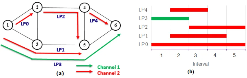
Fig. 3.3: an example of RWA and interval assignment
Fig. 3.3(a) shows five lightpath demands with their assigned routes and channels. Fig. 3.3(b) displays the starting time and ending time of each lightpath request. We
have introduced the calculation methods ofmaxLAR andmaxIAR in static networks. In the scheduled traffic model, a lightpathp that shares a common link with lightpath
q is not automatically in the attack group ofq. We havep∈AGq only if an additional condition is satisfied that p and q overlap in time. A similar condition must also be
satisfied for the in-band attack group, if two lightpathsp andq share a common node and wavelength. Also, unlike static lightpaths, the attack group for each lightpath is
not constant and may change with time as new lightpaths become active. Based on this, the LAR (IAR) for each lightpath in Fig 3.3, during differnet intervals, is given
III. SECURITY-AWARE SCHEDULED RWA
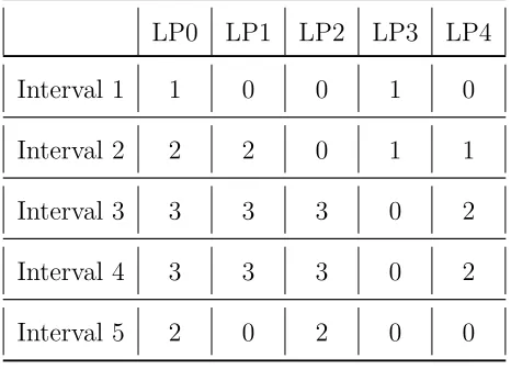
TABLE 3.1: the value of LAR of each lightpath during each interval
LP0 LP1 LP2 LP3 LP4
Interval 1 1 0 0 1 0
Interval 2 1 2 0 2 1
Interval 3 1 1 1 0 1
Interval 4 1 1 1 0 1
Interval 5 1 0 1 0 0
For example, in Interval 1, only LP0 and LP3 are active, but they do not traverse
any common link, so the values of LAR for LP0 and LP3 in Interval 1 are both 1. For the other lightpaths (LP1, LP2 and LP4) which are not active during interval 1,
their values of LAR are set to be 0. In interval 2, because LP1 and LP3 are both active and sharing the common links (1-3) and (3-5), hence LARLP1 and LARLP3 in
interval 2 is 1+1=2.
TABLE 3.2: the value of IAR of each lightpath during each interval
LP0 LP1 LP2 LP3 LP4
Interval 1 1 0 0 1 0
Interval 2 2 2 0 1 1
Interval 3 3 3 3 0 2
Interval 4 3 3 3 0 2
Interval 5 2 0 2 0 0
As described in Table 3.2, according to the definition of in-band Attack Radius,
III. SECURITY-AWARE SCHEDULED RWA
in interval 1 are both 1, while other lightpaths which are not active during interval 1
are set to be 0. In interval 2, LP0, LP1, LP3 and LP4 are all active, but only LP0 and LP1 share the same node and are on the same wavelength, so IARLP0 = IARLP1
=2. TheIAR values for each lightpath can be calculated in a similar fashion, for each interval.
3.3
Proposed ILP Formulation
3.3.1 ILP Formulation : ILP AR1
In this section, we formulate the routing sub-problem as an ILP with different
ob-jectives combining LAR and IAR to solve the security-aware scheduled RWA problem.
Input Parameters
G(N, E): Physical network topology
N: Set of nodes.
E: Set of edges.
W: Set of channels (wavelengths) on a fiber.
M: Number of intervals in the network.
hmax: An upper bound on the number of hops of a lightpath.
P: set of lightpaths.
sp, dp: source, destination of lightpath p.
Input Parameters to be pre-calculated
III. SECURITY-AWARE SCHEDULED RWA
tp,q ≤
X
m
ap,m·aq,m ∀p, q ∈P (2)
Constraints (1)-(2) are used to calculate whether or not two different lightpaths are time-disjoint or not. Iftp,q = 1, it means that lightpath p and q are not time-disjoint,
i.e. there is at least one time interval (possibly more) during which both lightpaths are active. The tp,q values are pre-calculated and given as input to the ILP.
Variables
ap,m=
1 if lightpath p is active during intervalm, 0 otherwise.
tp,q=
1 if lightpaths pand q are both active during one or more common intervals,
0 otherwise.
xp,e =
1 if lightpathp uses edge e , 0 otherwise.
yp,i =
1 if lightpathp passes through node i, 0 otherwise.
ωp,k =
1 if lightpathp is assigned channel k, 0 otherwise.
αp,q=
1 if lightpaths pand q share at least one common edge, 0 otherwise.
αep,q=
1 if lightpaths pand q share a common edge e, 0 otherwise.
βp,q =
1 if lightpaths p and q share at least one common node 0 otherwise.
βp,qi =
III. SECURITY-AWARE SCHEDULED RWA
γp,q =
1 if lightpaths pand q use the same channel, 0 otherwise. γk p,q =
1 if lightpaths pand q both use channelk, 0 otherwise.
δp,q =
1 if lightpaths p and q use the same channel and have at least one common node,
0 otherwise.
Notation Used
p,q: Used to identify an indivdual lightpath, p,q ∈ P .
e: Used to identify an a physical link (edge) of the network, e ∈ E.
i,j: Used to identify a specific node in the network, i,j ∈N.
k: Used to identify a specific channel on a fiber, k ∈ W.
m: Used to identify a specific time interval number,m = 1,2,3, ... M.
(1) Objective functions
Objective 1: Minimize
maxAR1 (3)
maxAR1 is the upper bound of AR1p,m = IARp,m + LARp,m, for any lightpath p in
any interval m of the network.
III. SECURITY-AWARE SCHEDULED RWA
1. Flow Conservation Constraints
X
e:i→j∈E
xp,e−
X
e:j→i∈E
xp,e =
1 if i=sp
−1 if i=dp ∀i∈N,∀p∈P 0 otherwise.
(4)
X
e:i→j∈E
xp,e≤1 ∀i∈N,∀p∈P (5)
Constraints (4) and (5) ensure flow conservation of lightpaths. Constraint (4) finds a
valid path over the physical topology, for each lightpath. Constraint (5) ensures that the path does not contain any loops.
2. Wavelength continuity constraint
X
k
ωp,k= 1 ∀p∈P (6)
Constraints (6) ensures that a lightpath must be assigned the same wavelength on each link it passes without wavelength conversion.
3. Defining αp,q (link sharing)
xp,e+xq,e−αep,q≤1 ∀p, q ∈P, p6=q,∀e∈E (7)
xp,e ≥αep,q ∀p, q ∈P, p 6=q,∀e∈E (8)
xq,e ≥αep,q ∀p, q ∈P, p 6=q,∀e ∈E (9)
III. SECURITY-AWARE SCHEDULED RWA
αp,q ≤
X
e∈E
αep,q ∀p, q ∈P, p 6=q (11)
Constraints (7)-(9) sets the value of αep,q = 1 if lightpath p and lightpathq are both routed over link e. Constraints (10) and (11) determine if two lightpaths p and q
share at least one (possibly more) common link(s), and if so, set αp,q = 1.
4. Node usage constraint
yp,i =
X
e:i→j∈E
xp,e ∀p∈P,∀i∈N, i6=dp (12)
yp,dp = 1 ∀p∈P (13)
Constraint (12) determines if a lightpath p traverses a specific node i in its selected route. If so the value of yp,i is set to 1. Constraint (13) states that the destination node of a lightpath must be on the selected route.
5. Defining βp,q (node sharing)
yp,i+yq,i−βp,qi ≤1 ∀p, q ∈P, p 6=q,∀i∈N (14)
yp,i ≥βp,qi ∀p, q ∈P, p 6=q,∀i∈N (15)
yq,i ≥βp,qi ∀p, q ∈P, p 6=q,∀i∈N (16)
III. SECURITY-AWARE SCHEDULED RWA
βp,q ≤
X
i∈N
βp,qi ∀p, q ∈P, p 6=q (18)
Constraint (14)-(18) are very similar to constraint (7)-(11) and are used to determine if two lightpathspand lightpathq pass through at least one (possibly more) common
node(s). If so these constraints are used to set βp,q=1.
6. Defining γp,q (channel sharing)
ωp,k+ωq,k−γp,qk ≤1 ∀p, q ∈P, p 6=q,∀k∈W (19)
ωp,k ≥γp,qk ∀p, q ∈P, p6=q,∀k ∈W (20)
ωq,k ≥γp,qk ∀p, q ∈P, p6=q,∀k ∈W (21)
γp,q =
X
k
γp,qk ∀p, q ∈P, p 6=q (22)
Similarly, constraint (19)-(22) are applied to define channel-sharing and set the value of γp,q = 1, if lightpath p and lightpath q are assigned the same channel (or wave-length)k.
7. Defining δp,q (node-channel sharing)
βp,q+γp,q−δp,q≤1 ∀p, q ∈P, p6=q (23)
III. SECURITY-AWARE SCHEDULED RWA
γp,q ≥δp,q ∀p, q ∈P, p 6=q (25)
Constraint (23)-(25) define node-channel sharing. If lightpath p and q pass through at least one common node (i.e. βp,q = 1) and share the same channel (i.e. γp,q = 1), then we set δp,q=1. The value of this variable determines if lightpath p might be in the attack group of lightpath q.
8. wavelength clash constraint
αp,q+γp,q+tp,q ≤2 ∀p, q ∈P, p 6=q (26)
Constraint (26) ensures that if two or more lightpaths share a common fiber link, they cannot be assigned the same wavelength.
9. LAR/IAR of lightpathp (attack radius in interval m)
LARp,m =ap,m·(
X
q∈P,p6=q
αp,q·aq,m+ 1) ∀p∈P,∀m= 1,2, ..., M (27)
IARp,m =ap,m·(
X
q∈P,p6=q
δp,q·aq,m+ 1) ∀p∈P,∀m= 1,2, ..., M (28)
Constraint (27) (constraint (28)) is used to calculate Lightpath Attack Radius (LAR)
( In-band Attack Radius (IAR)) value for lightpath p during interval m. The goal is to keep this value as low as possible.
10. Total LAR and IAR of lightpath p (over all intervals)
LARp =
X
q∈P,p6=q
III. SECURITY-AWARE SCHEDULED RWA
IARp =
X
q∈P,p6=q
δp,q·tp,q+ 1 ∀p∈P (30)
Constraint (29) (constraint (30)) defines the total Lightpath Attack Radius (LAR) (In-band Attack Radius (IAR)) value for lightpath p over all intervals.
11. MaxAR1 in interval m
IARp,m+LARp,m ≤maxAR1 ∀p∈P,∀m= 1,2, ..., M (31)
Constraint (31) ensures that the total attack radius of any lightpath p during any given time interval m (i.e. AR1p,m = IARp,m + LARp,m) is no greater than the maxAR1, which is the value being minimized.
12. Total maxAR2 over all intervals
IARp+LARp ≤maxAR2 ∀p∈P (32)
Constraint (32) ensures that the total attack radius of any lightpath (over all
inter-vals),maxAR2. This variable can be minimized (instead ofmaxAR1) as an alternative objective function
13. Hop Bound Constraints
X
e:i→j∈E
xp,e ≤hmax ∀p∈P (33)
III. SECURITY-AWARE SCHEDULED RWA
By solving the ILP formulation above, we can get the optimal routing scheme with regard to proposed objective function.
3.4
Alternative objective functions
In this section, we consider some alternative objective functions that can be used,
with the same set of constraints as discussed in the previous section.
3.4.1 ILP Formulation : ILP AR2
This formulation is similar to ILP AR1 presented in the previous section, with the
following modification.
Objective function is modified as follows:
Objective 2: Minimize
maxAR2 (34)
maxAR2 is the upper bound of AR2p = IARp + LARp, for all lightpath p ∈ P. So this objective minimizes the maximum Attack Radius (AR2 value) for any lightpath.
All other variables and constraints are identical to ILP AR1.
3.4.2 ILP Formulation : ILP SUM AR2
The ILP formulation regarding ILP SUM AR2 is also similar to ILP AR1 presented in the previous section, with the following modification.
Objective function is modified as follows: Objective 3: Minimize
X
p∈P
LARp+IARp (35)
III. SECURITY-AWARE SCHEDULED RWA
of all the lightpath over all intervals. It is the summation of AR2 of each lightpath.
All other variables and constraints are identical to ILP AR1.
3.4.3 ILP Formulation : ILP SUM AR1
The ILP formulation with regard to ILP SUM AR1 is also similar to ILP AR1
presented in the previous section, with the following modification. Objective function is modified as follows:
Objective 4: Minimize
X
m
X
p∈P
LARp,m+IARp,m (36)
Objective 4 minimizes the total attack radius (AR1p,m =IARp,m +LARp,m) over
all lightpaths and all intervals.
All other variables and constraints are identical to ILP AR1.
3.4.4 ILP Formulation : ILP SPATH
This formulation does not consider attacks but simply minimizes the total path
length of all lightpaths. So, this is a traditional attack-unaware ILP for RWA.
Objective function is modified as follows:
Objective 5: Minimize
X
p∈P
X
e∈E
xp,e (37)
III. SECURITY-AWARE SCHEDULED RWA
3.4.5 Summary of ILP Objectives
In summary, there are five objective functions proposed in this chapter, as presented below:
TABLE 3.3: Proposed ILP formulations and objectives
ID ILP Formulation Name Objectives
Objective 1 ILP AR1 Minimize maxAR1
Objective 2 ILP AR2 Minimize maxAR2
Objective 3 ILP SUM AR2 Minimize P
p LARp + IARp
Objective 4 ILP SUM AR1 Minimize P
m
P
p LARp,m+IARp,m
Objective 5 ILP SPATH MinimizeP
p
P
e xp,e
Objective 1 to Objective 4 are our proposed attack-aware objectives in order to minimize the attack radius of a network, while Objective 5 is a traditional
attack-unaware approach aimed at minimizing the total physical links used. Then we will create C programs to implement all the five ILP formulations and run different
CHAPTER IV
Experimental Results
In this chapter, we present different simulation cases and the results of RWA problem
from our proposed approach.We also compare the objective values obtained using our approach ILP AR1, ILP AR2, ILP SUM AR2 and ILP SUM AR1 with the
cor-responding values obtained using a traditional attack-unaware RWA scheme.
Unlike existing attack-aware RWA techniques, we consider the scheduled traffic
model, which means we consider the time dimension in our proposed ILP formulation, Furthermore, traditional static RWA can be treated as a special case of our approach
(by setting a single time interval for all the lightpath demands). Finally, the objectives in our ILP formulation takes into account both in-band attack radius (IAR) and
lightpath attack radius (LAR), so it can handle multiple types of attacks.
4.1
Experimental Setup
We test the proposed ILP formulation with different network topologies and lightpath
demand sets. For each topology and demand set size, we considered 3 levels of traffic load - low, medium and high, and for each case, we used 5 randomly generated
de-mand sets. So, the results reported in this chapter are the average of 5 simulation runs.
• Simulations of different network topologies
20 demands for 10-node network
IV. EXPERIMENTAL RESULTS
• Simulations of different demand size
14-node network with 10 demands
14-node network with 20 demands 14-node network with 40 demands
4.1.1 Physical Topologies
We have considered 3 well-known physical topologies: a 10-node network with 22
bi-directional links[32], a 14-node network with 21 bi-directional links[31] and a 20-node network with 31 bi-directional links[30]. We also assume that each fiber
(uni-directional) can accommodate 16 channels (wavelengths). Each physical topology is saved in a text file, following the format in Fig. 4.1.
1 2 1 3 1 4 2 1 3 1 3 4 4 1 4 3 (b)
Fig. 4.1: an example of network topology and its physical-link storage format
Fig 4.1(a) shows a simple network topology with 4 nodes and 4 bi-directional links
(8 uni-directional fibers). Each row in Fig.4.1(b) represents a uni-directional fiber link specified by the starting and ending node of the link.
4.1.2 Lightpath Demand Sets
A set of scheduled lightpath demands is specified as a m*4 matrix, where m is the
demand set size, i.e. the number of lightpaths in the demand set. Each row represents a single lightpath (p) and specifies its source (sp), destination (dp), start time(stp)
IV. EXPERIMENTAL RESULTS
1 4 3 10
1 2 5 23
1 3 17 19
(b)
Fig. 4.2: an example of (a)RWA scheme and (b)its lightpath demand storage format
Fig 4.2(b) shows a set of 3 lightpath demands (Row 1: LP0, Row 2: LP1, Row 3: LP2). For example, (LP0: 1 4 3 10) means LP0 is a lightpath demand from node 1
to node 4 and it is active during interval 3 to interval 10. A possible routing for the demand set of Fig. 4.2(b) is shown in Fig. 4.2(a).
In addition, we classify the lightpath demand sets into three categories according to the time span of each demand. The longer the duration of a demand, the more
resources it uses. Also, if a demand set consists of longer demands, it is likely that that there will be more overlap (in time) among different demands leading to a larger
attack group. Based on this observation, we define the following three classes of demand sets:
• Low demand overlap (LDO): For a LDO demand set, the duration of each
demand is between 1 and 10 intervals.
1≤(last interval−f irst interval)≤10
• Medium demand overlap (MDO): For a MDO demand set, the duration of each
demand is between 1 and 24 intervals.
1≤(last interval−f irst interval)≤24
IV. EXPERIMENTAL RESULTS
demand is between 10 and 24 intervals.
10≤(last interval−f irst interval)≤24
Next, we will run the ILP formulation with the objectives of our approach ILP AR1, ILP AR2, ILP SUM AR2, ILP SUM AR1 and the shortest path ILP SPATH for all
the parts of simulations presented above.
4.2
Results of Experiment
In this section, we will run our ILP formulation with the 5 different objective functions
presented in Chapter 3, denoted as ILP AR1 for Objective 1, ILP AR2 for Objective 2, ILP SUM AR2 for Objective 3, ILP SUM AR1 for Objective 4 and ILP SPATH
for Objective 5. CPLEX ver. 12.6 is used for solving linear programming problems. For each network topology, the lightpath demands are randomly generated based on
the demand size traffic load (LDO, MDO, HDO).
We compare our proposed algorithm with a traditional security-unaware algorithm
(denoted as ILP SPATH), which aims at minimizing the total path length for the set of lightpaths and does not consider their vulnerability to attacks.
4.2.1 Comparison of objective values for different networks
Table 4.1 compares the value of Objective 1 (maxAR1) for the proposed approach
IV. EXPERIMENTAL RESULTS
TABLE 4.1: Comparison of Objective 1 for 20 Demands
Objective function: maxAR1
LDO MDO HDO
No. of Nodes Proposed Approach Attack-unaware Approach Proposed Approach Attack-unaware Approach Proposed Approach Attack-unaware Approach
10 2 4 2 5 3 6
14 3 4 3 5 5 6
20 3 5 4 7 7 9
We can see from Table 4.1 that the values of maxAR1 obtained using our proposed algorithm (ILP AR1) are consistently lower than those obtained using the traditional
attack-unaware algorithm (ILP SPATH). The achieved reductions range from 16.7% - 60%. Comparisons for Objectives 2, 3, and 4 are presented in Table 4.2, 4.3 and 4.4
respectively.
TABLE 4.2: Comparison of Objective 2 for 20 Demands
Objective function: maxAR2
LDO MDO HDO
No. of Nodes Proposed Approach Attack-unaware Approach Proposed Approach Attack-unaware Approach Proposed Approach Attack-unaware Approach
10 2 4 2 6 3 6
14 3 4 5 6 5 7
IV. EXPERIMENTAL RESULTS
TABLE 4.3: Comparison of Objective 3 for 20 Demands
Objective function: P
p LARp + IARp
LDO MDO HDO
No. of Nodes Proposed Approach Attack-unaware Approach Proposed Approach Attack-unaware Approach Proposed Approach Attack-unaware Approach
10 40 50 40 60 47 80
14 41 54 48 79 56 93
20 43 62 53 82 64 97
TABLE 4.4: Comparison of Objective 4 for 20 Demands
Objective function: P
m Pp LARp,m+IARp,m
LDO MDO HDO
No. of Nodes Proposed Approach Attack-unaware Approach Proposed Approach Attack-unaware Approach Proposed Approach Attack-unaware Approach
10 210 253 304 394 689 965
14 190 230 448 571 823 995
20 208 254 450 618 850 1169
Table 4.2 - Table 4.4 clearly demonstrate that our proposed approach results in
smaller values of attack radius for all cases. The average reductions range from 16.7% (for Objective 2) to 66.7% (for Objective 2).
Fig. 4.3 - Fig. 4.5 show the comparison results for Objective 4 for different levels of demand overlap. The network size is shown along the x-axis and the value of attack
radius on y-axis. The improvements range from 17.0% (for LDO case) to 28.6% (for HDO case). For each network, the objective value increases with the level of demand
IV. EXPERIMENTAL RESULTS
more interactions among lightpaths. The results for the other objectives follow a
similar pattern.
Fig. 4.3: Results of Objective 4 for LDO with 20 demands
IV. EXPERIMENTAL RESULTS
Fig. 4.5: Results of Objective 4 for HDO with 20 demands
4.2.2 Comparison of objective values of various demand sizes
Table 4.5 - Table 4.8 show how each objective value varies with the demand size for
the 14-node network topology.
TABLE 4.5: Comparison of Objective 1 values with different demand sizes for 14-node Network
Objective function: maxAR1
LDO MDO HDO
No. of
Demands
Proposed
Approach
Attack-unaware Approach
Proposed
Approach
Attack-unaware Approach
Proposed
Approach
Attack-unaware Approach
10 2 4 2 5 2 6
20 3 4 3 5 5 6
IV. EXPERIMENTAL RESULTS
TABLE 4.6: Comparison of Objective 2 values with different demand sizes for 14-node Network
Objective function: maxAR2
LDO MDO HDO
No. of Demands Proposed Approach Attack-unaware Approach Proposed Approach Attack-unaware Approach Proposed Approach Attack-unaware Approach
10 2 4 2 4 2 6
20 3 4 5 6 5 7
40 5 7 7 13 7 12
TABLE 4.7: Comparison of Objective 3 values with different demand sizes for 14-node Network
Objective function: P
p LARp + IARp
LDO MDO HDO
No. of Demands Proposed Approach Attack-unaware Approach Proposed Approach Attack-unaware Approach Proposed Approach Attack-unaware Approach
10 20 38 25 46 31 54
20 41 54 48 79 56 93
IV. EXPERIMENTAL RESULTS
TABLE 4.8: Comparison of Objective 4 values with different demand sizes for 14-node Network
Objective function: P
m Pp LARp,m+IARp,m
LDO MDO HDO
No. of Demands
Proposed Approach
Attack-unaware
Approach
Proposed Approach
Attack-unaware
Approach
Proposed Approach
Attack-unaware
Approach
10 96 162 132 166 278 460
20 190 230 448 571 823 995
40 507 601 1062 1317 2323 2867
As expected the objective values increase steadily with demand size for all net-works for both the proposed approach and the attack-unaware approach. The average
improvements obtained using the proposed approach range from 16.7% to 66.7%.
IV. EXPERIMENTAL RESULTS
Fig. 4.7: Variation of Objective 4 with demand size in 14-node network for MDO
Fig. 4.8: Variation of Objective 4 with demand size in 14-node network for HDO
Fig. 4.6 - Fig. 4.8 show how the values for Objective 4 vary with demand size, in a 14-node network, for LDO, MDO and HDO traffic respectively. The demand set size
IV. EXPERIMENTAL RESULTS
range from 15.6% (for LDO case) to 40.7% (for LDO case). For each network, the
objective value increases with the size of the demand set. The results for the other objectives follow a similar pattern.
4.2.3 Comparison of path lengths
Table 4.9 - Table 4.11 compare the average path length of a lightpath using the
different approaches for LDO, MDO and HDO traffic respectively.
TABLE 4.9: Comparison of average path lengths for LDO traffic
Average path length obtained using
Proposed approach Attack-unaware
No. of
Nodes
Objective 1 Objective 2 Objective 3 Objective 4 ILP SPATH
10 2.15 2.0 2.2 2.3 1.6
14 2.55 2.8 3.35 3.35 1.95
20 4.05 3.65 4.35 3.9 2.9
TABLE 4.10: Comparison of average path lengths for MDO traffic
Average path length obtained using
Proposed approach Attack-unaware
No. of
Nodes
Objective 1 Objective 2 Objective 3 Objective 4 ILP SPATH
10 2.2 2.1 2.25 2.35 1.55
14 3 2.8 3 3.45 1.95
IV. EXPERIMENTAL RESULTS
TABLE 4.11: Comparison of average path lengths for HDO traffic
Average path length obtained using
Proposed approach Attack-unaware
No. of
Nodes
Objective 1 Objective 2 Objective 3 Objective 4 ILP SPATH
10 2.35 2.35 2.15 2.05 1.6
14 2.45 2.4 2.7 2.85 1.95
20 3.4 3.5 3.85 3.7 2.75
Based on Tables 4.9 - 4.11, we can see that the attack-unaware algorithm (ILP SPATH) results in shorter paths on average. This is because it always selects the shortest
path, even if the route is heavily congested. The attack-aware approaches on the other hand try to distribute the load so that potential interactions among lightpaths
is minimized. This may result in selecting longer, but less congested, paths for some lightpaths. However, considering the security issue, the increase of path lengths is
![Fig. 1.1: Optical Fiber Cable & Metal Cable [12]](https://thumb-us.123doks.com/thumbv2/123dok_us/1392577.1171956/15.612.173.490.529.617/fig-optical-fiber-cable-metal-cable.webp)
![Fig. 1.4: Transparent Optical Network Topology [14]](https://thumb-us.123doks.com/thumbv2/123dok_us/1392577.1171956/16.612.152.480.523.600/fig-transparent-optical-network-topology.webp)
![Fig. 1.5: a wavelength-routed optical network with lightpath connections [17]](https://thumb-us.123doks.com/thumbv2/123dok_us/1392577.1171956/17.612.178.458.351.500/fig-wavelength-routed-optical-network-lightpath-connections.webp)


![Fig. 2.10: A New Detection Method[21]](https://thumb-us.123doks.com/thumbv2/123dok_us/1392577.1171956/34.612.193.435.408.609/fig-a-new-detection-method.webp)