ISSN (Print) : 2320 – 3765 ISSN (Online): 2278 – 8875
I
nternational
J
ournal of
A
dvanced
R
esearch in
E
lectrical,
E
lectronics and
I
nstrumentation
E
ngineering
(An ISO 3297: 2007 Certified Organization)
Website: www.ijareeie.com
Vol. 6, Issue 1, January 2017
Design of Floating Point Adder/Subtractor
and Floating Point Multiplier for FFT
Architecture Using VHDL
Rutuja R. Taksande1, Prof. Mangesh N.Thakare2, Prof. Girish D. Korde3 PG Student [VLSI], Dept. of EXTC, BDCOE, Sewagram, Maharastra, India1
Associate Professor, Dept. of EXTC, BDCOE, Sewagram, Maharastra , India2
Assistant Professor, Dept. of EXTC, BDCOE, Sewagram, Maharastra, India3
ABSTRACT: A Fast Fourier transform algorithm computes the discrete Fourier transform of a sequence, or it’s inverse. Fourier analysis converts a signal from its original domain (often time or space) to a representation in the frequency domain and vice versa. This Paper presents design, synthesis and simulation of floating point adder, subtractor and multiplier unit which will be later on used in the design of FFT architecture. These three modules will be required for the design of floating point complex number multiplier. The coding has been done in VHDL and design, synthesis and simulation will be done using XILINX ISE 14.5. The delay obtained for floating point adder is 12.064ns, floating point subtractor is 14.633 ns and floating point multiplier is 18.623 ns.
KEYWORDS: Fast Fourier Transform, Floating point arithmetic, XILINX ISE 14.5i, VHDL.
I.INTRODUCTION
The FFT is one of the most commonly used digital signal processing algorithm. Recently, FFT processor has been widely used in digital signal processing field applied for communication systems. FFT processors are key components for an orthogonal Frequency Division Multiplexing (OFDM) based wireless broadband communication system; it is one of the most complex and intensive computation module of various wireless standards PHY layer.[1]
Floating point presents a system for representation of numbers that can be too small or too large to be represented in the form of integers. Representation of floating point numbers is able to retain its accuracy and resolution as compared to representation of fixed point numbers. The numbers are represented in scaled form in multiple of binary base. For representation of the number, significant digit is multiplied by its base with power of exponent. Whereas for representing floating point numbers, IEEE 754 standard is used in digital system.
ISSN (Print) : 2320 – 3765 ISSN (Online): 2278 – 8875
I
nternational
J
ournal of
A
dvanced
R
esearch in
E
lectrical,
E
lectronics and
I
nstrumentation
E
ngineering
(An ISO 3297: 2007 Certified Organization)
Website: www.ijareeie.com
Vol. 6, Issue 1, January 2017
II
.
IEEE 754-2008 ARITHMETICIEEE standard 754 floating point is the most common representation today for real numbers on computers, including Intel-based PC’s, Macintoshes, and most UNIX platforms. The IEEE standard for floating point arithmetic is most widely used standard for floating point computation and it is followed by many software and hardware implementation. Many computer languages allow or require that some or all arithmetic be carried out using IEEE 754 formats and operations. Similarly, IEEE standard for binary floating point arithmetic (IEEE 754-2008) is most widely used standard for floating point computation and it is followed by many CPU and FPU implementation.
The 32-bit format for IEEE 754-2008 standard is as follows;
Fig.1 IEEE 754-2008 Standard’s Single Precision Format
The IEEE 754-2008 standard’s 32-bit single precision floating point format is as shown in figure above. It consists of three field’s viz. Sign field of 1-bit, Exponent field of 8-bits and Significant/Mantissa field of 23-bits.
I. The Sign Field
The sign bit is as simple as it gets, it is of single bit in size. ‘0’ denotes a positive number and ‘1’ denotes negative number.
II. The Exponent Field
The exponent field is of 8-bit in size. This field needs to represent both positive and negative exponents. To do this, a bias is added to the actual exponent in order to get the stored exponent. For IEEE single precision floats, this value is 127, since exponent field is of 8-bit, therefore by using the formula 2n-1 – 1, we can easily calculate the bias value, where ‘n’ is the exponent’s bit. Hence , 28-1 – 1 = 27 – 1 = 128 – 1 = 127. Thus, an exponent of zero means that 127 is stored in the exponent field.. Similarly, exponents of -127 (all 0s) and +128 (all 1s) are reserved for special numbers. For double precision i.e. 64-bit, the exponent field is 11-bits and has a bias of 1023.
III. The Significand/mantissa
The mantissa, also called as significand, represents the precision bits of the number. It is composed of an implicit leading bit and the fraction bits.
To find out the value of the implicit leading bit, consider that any number can be expressed in scientific notation in many different ways. For example, the number 5 can be represented as any of these:
5.00 x 100 0.05 x 10² 5000 x 10-3
In order to maximize the quantity of numbers which are represented, floating point numbers are typically stored in normalized form. This basically puts the radix point after the first non-zero digit. In normalized form, 5 are represented as 5.0 x 100.
From the above discussion we can say that,
The sign bit is 0 for positive numbers, 1 for negative numbers.
The base of exponent is 2.
The exponent field contains 127 plus the true exponent for single precision, or 1023 plus the true exponent for double precision.
The first bit of significand/mantissa is typically assumed to be 1.f, where ‘f’ is the field of fraction bits.[3] S E x p o n e n t S i g n i f i c a n d / M a n t i s s a
ISSN (Print) : 2320 – 3765 ISSN (Online): 2278 – 8875
I
nternational
J
ournal of
A
dvanced
R
esearch in
E
lectrical,
E
lectronics and
I
nstrumentation
E
ngineering
(An ISO 3297: 2007 Certified Organization)
Website: www.ijareeie.com
Vol. 6, Issue 1, January 2017
III.FLOATING POINT CONVERSION
The steps for conversion of a decimal number into floating point number or to write a decimal number into IEEE 754 format are as follows;
If number is positive then the sign bit is 0, otherwise 1.
Convert the decimal number into binary number.
Write it into standard form.
Calculate its exponent.
Use formula 2n-1-1, where n is the exponent bits.
Add exponent to it for biasing.
Convert the exponent into binary.
Finally, write the number i.e. sign, significand/mantissa and exponent bits into the standard IEEE 754 format. Let us see an example that how to write a decimal number into IEEE 754 single precision floating point format. Example: - Write (2345.125)10 in IEEE 754 format.
Steps:-
Convert decimal number into binary number (2345.125)10 = (100100101001.001)2
Write the obtained number into Standard Form = 1.00100101001001x10¹¹
Calculate its Exponent = 11
Biased the number, 2n-1-1 = 28-1-1 = 128-1 = 127
Add exponent to the true exponent, 11+127 = 138
Convert decimal exponent into binary exponent (138)10 = (10001010)2
The number obtained is 1.00100101001001000000000 x 2138 .[6]
Fig. 2 Conversion of Decimal to Floating Point Number
IV.ARITHMETIC OPERATIONS PERFORMED BY IEEE 754 STANDARDS
[1] Floating Point Addition / Subtraction Algorithm
Assuming that the operands are already in the IEEE 754 format, performing floating point addition / subtraction: Addition = X + Y = (Xm x 2Xe) + (Ym x 2Ye) or
Subtract = X - Y = (Xm x 2Xe) - (Ym x 2Ye) This algorithm involves the following steps: (i) Align binary point
Initial result exponent: the larger of Xe, Ye.
Compute exponent difference: Ye – Xe.
If Ye >Xe Right shift Xm that many positions to form Xm 2 Xe - Ye.
If Xe> Ye Right shift Ym that many positions to form Ym 2 Ye - Xe. (ii) Compute sum of aligned mantissas
Xm2 Xe-Ye + Ym or Xm + Xm2 Ye-Xe.
(iii) If normalization of result is needed, then a normalization step follows
Left shift result, decrement result exponent (e.g., if result is 0.001xx…) or
Right shift result, increment result exponent (e.g., if result is 10.1xx…) Continue until MSB of data is 1. (iv) Check result exponent
0 1 0 00 10 1 0 00100101001001000000000 (31) (30 to 24) (23 to 0)
ISSN (Print) : 2320 – 3765 ISSN (Online): 2278 – 8875
I
nternational
J
ournal of
A
dvanced
R
esearch in
E
lectrical,
E
lectronics and
I
nstrumentation
E
ngineering
(An ISO 3297: 2007 Certified Organization)
Website: www.ijareeie.com
Vol. 6, Issue 1, January 2017
If smaller than minimum exponent allowed return exponent underflow.
(v) If result mantissa is 0, may need to set the exponent to zero by a special step to return a proper zero.[3] The flow chart for floating point addition / subtraction is shown in figure below.
Fig. 3 Flow Chart for Addition / Subtraction [3]
The block diagram of floating point adder is shown in the figure 4. There will be XOR operation on Sign bits of the two numbers, exponents get normalized and mantissa gets added/subtracted to get the required floating point addition/subtraction.
Fig.4. Block Diagram Of Standard Floating Point Adder/subtractor [4]
[2] Floating Point Multiplication Algorithm
Assuming that the operands are already in the IEEE 754 format, performing floating point multiplication: Multiplication = R=X * Y = (-1)Xs (Xm x 2Xe) * (-1)Ys (Ym x 2Ye)
ISSN (Print) : 2320 – 3765 ISSN (Online): 2278 – 8875
I
nternational
J
ournal of
A
dvanced
R
esearch in
E
lectrical,
E
lectronics and
I
nstrumentation
E
ngineering
(An ISO 3297: 2007 Certified Organization)
Website: www.ijareeie.com
Vol. 6, Issue 1, January 2017
Fig.5 Flow Chart for Multiplication [3]
This algorithm involves the following steps:
(i) If one or both operands is equal to zero, return the result as zero, otherwise.
(ii) Compute the sign of the result Xs XOR Ys.
(iii) Compute the mantissa of the result:
Multiply the mantissas: Xm * Ym.
Round the result to the allowed number of mantissa bits.
(iv) Compute the exponent of the result:
Result exponent = biased exponent (X) + biased exponent (Y) – bias.
(v) Normalize if needed, by shifting mantissa right, incrementing result exponent.
(vi) Check result exponent for overflow/underflow:
If larger than maximum exponent allowed return exponent overflow.
If smaller than minimum exponent allowed return exponent underflow.
Fig.6 Block Diagram of Standard Floating Point Multiplier [5]
ISSN (Print) : 2320 – 3765 ISSN (Online): 2278 – 8875
I
nternational
J
ournal of
A
dvanced
R
esearch in
E
lectrical,
E
lectronics and
I
nstrumentation
E
ngineering
(An ISO 3297: 2007 Certified Organization)
Website: www.ijareeie.com
Vol. 6, Issue 1, January 2017
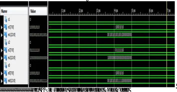
V. SIMULATION RESULTS
Fig.10, Fig.11, Fig.12 shows the simulation result of floating point adder, floating point subtractor, floating point multiplier. Delay obtained by floating point adder is 12.064 ns. Delay obtained by floating point subtractor is 14.633 ns and Delay obtained by floating point multiplier is 18.623 ns.
FLOATING POINT ADDER
Fig. 10Simulation result of Floating Point Adder
Figure 10 shows floating point addition of two inputs, inputs are “01000101000100101001001000000000” and “00111111010000000000000000000000” and the obtained output is “01000101000100101001111000000000”.
FLOATING POINT SUBTRACTOR
Fig.11 Simulation result of Floating Point Subtractor
ISSN (Print) : 2320 – 3765 ISSN (Online): 2278 – 8875
I
nternational
J
ournal of
A
dvanced
R
esearch in
E
lectrical,
E
lectronics and
I
nstrumentation
E
ngineering
(An ISO 3297: 2007 Certified Organization)
Website: www.ijareeie.com
Vol. 6, Issue 1, January 2017
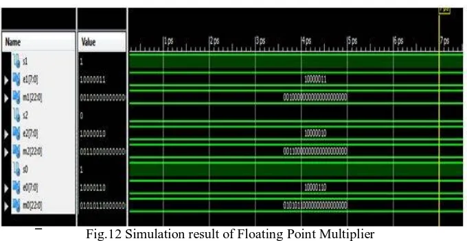
FLOATING POINT MULTIPLIER
Fig.12 Simulation result of Floating Point Multiplier
Figure 12 shows floating point multiplication of two inputs, inputs are “01000101000100101001001000000000” and “00111111010000000000000000000000” and the obtained output is “01000101000100101001111000000000”.
Table 1: Example of Floating Point Operation
INPUT-1 INPUT-2 OUTPUT DELAY
FPA 010001010001001010010010 00000000
001111110100000000000000000
00000 01000101000100101001111000000000
12.064ns
FPS 010001010001001010010 01000000000
0011111101000000000000000 0000000
01000101000100101001111000000 000
14.633ns
FPM 010001010001001010010 01000000000
0011111101000000000000000 0000000
01000101000100101001111000000 000
18.623ns
Fig.10, Fig.11, Fig.12 shows the simulation result of floating point adder, floating point subtractor, floating point multiplier. Delay obtained by floating point adder is 12.064 ns. Delay obtained by floating point subtractor is 14.633 ns and Delay obtained by floating point multiplier is 18.623 ns.
VI.CONCLUSION
In this paper, we use top-down design method in which we design floating point adder/subtraction and floating point multiplier. VHDL language has been used to describe the system. The 32-bit single precision floating point adder/subtraction& multiplier has been designed. The design is verified through exhaustive simulations. The design, synthesis and simulation of 32-bit single precision floating point adder/subtraction & multiplier have been achieved using Xilinx 14.5i ISE tool.
ISSN (Print) : 2320 – 3765 ISSN (Online): 2278 – 8875
I
nternational
J
ournal of
A
dvanced
R
esearch in
E
lectrical,
E
lectronics and
I
nstrumentation
E
ngineering
(An ISO 3297: 2007 Certified Organization)
Website: www.ijareeie.com
Vol. 6, Issue 1, January 2017
REFERENCES
[1] Soundarya .G, Naveen ,V.Jagan and Rao,D.Tirumala,“ Implementation of 32-point FFT processor for OFDM system”.© Springer India
2015L.C. Jain et al. (eds.), Computational Intelligence in Data Mining -Volume 3,Smart Innovation, Systems and Technologies 33, DOI 10.1007/978-81-322-2202-6_20.
[2] Singh,R.R Tiwari Asish , Singh,Vinay.Kumar, Tomar,Geetam. S, “VHDL environment for floating point Arithmetic Logic Unit - ALU design
and simulation”, 2011 International Conference on Communication Systems and Network Technologies, 978-0-7695-4437-3/11 $26.00 © 2011 IEEE.
[3] Itagi,MahiP.a and Kerurb S. S, “Design and Simulation of Floating Point Pipelined ALU Using HDL and IP Core Generator”, International Journal of Current Engineering and Technology, ISSN 2277 – 4106 ©2013 INPRESSCO.
[4] Dhobale. Rupali, Chaturvedi .Soni , “Implementation of 32 Bit Binary Floating Point Adder Using IEEE754 Single Precision Format” , IOSR
Journal of VLSI and Signal Processing (IOSR-JVSP) Volume 5, Issue 1, Ver. I (Jan-Feb. 2015), PP 50-53, e-ISSN: 2319–4200, p-ISSN No. : 2319–4197.
[5] Sachan.Pragati, “VHDL Implementation of floating point multiplier based on Vedic multiplication Technique”, International Journal of
Science, Engineering and Technology, volume 3, issue 4, 2015.
![Fig. 3 Flow Chart for Addition / Subtraction [3]](https://thumb-us.123doks.com/thumbv2/123dok_us/7772122.1280164/4.595.170.427.500.684/fig-flow-chart-addition-subtraction.webp)