Efficient Group Key Management
Schemes for Multicast Dynamic
Communication Systems
Muhammad Yasir Malik
i
Abstract
Key management in multicast dynamic groups, where users can leave or join
at their ease is one of the most crucial and essential part of secure
communication. Various efficient management strategies have been proposed
during last decade that aim to decrease encryption costs and transmission
overheads. In this report, two different types of key management schemes are
proposed. First proposed scheme is based on One-way function tree (OFT).
The proposed scheme fulfills the security gaps that have been pointed out in
recent years. Second proposed scheme is based on logical key hierarchy
(LKH). This proposed scheme provides better performance for, rather
inflexible and expensive, LKH scheme.
Keywords: Group communication, key management (KM), logical key
ii
Table of Contents
Table of Contents ... ii
List of Tables ... v
1
Introduction ... 1
1.1 Background ... 1
1.2 Security Requirements ... 3
1.3 Objectives ... 4
2
Key Management Schemes ... 5
2.1 Logical Key Hierarchy ... 5
2.1.1 LKH Tree Structure ... 5
2.1.2 On User Join ... 6
2.1.3 On User Leave ... 7
2.2 One-Way Function Key Tree ... 8
2.2.1 OFT Structure ... 9
2.2.2 On User Join ... 10
2.2.3 On User Leave ... 11
2.3 Collusion Attacks on OFT ... 11
2.3.1 Horng’s Attack ... 11
2.3.2 Ku and Chen’s Attack ... 13
2.4 Security Requirements ... 14
3
New Secure OFT Scheme ... 16
3.1 Introduction ... 16
3.2 On User Leave ... 19
3.2.1 Key Requirements ... 19
3.2.2 Algorithm on User Eviction ... 20
3.2.3 An Example of User Eviction ... 21
3.3 Simulation and Results ... 23
3.4 Security Analysis of Proposed Scheme ... 24
4
Multicast Scheme Based on LKH ... 27
4.1 System Design ... 27
4.1.1 Design Principles ... 27
4.1.2 Detailed Outline ... 27
4.2 On User Join ... 29
4.2.1 Key Requirements ... 29
iii
4.3 On User Leave ... 31
4.3.1 Key Requirements ... 32
4.3.2 Protocol for User Leave ... 32
4.4 Simulation and Results ... 33
4.4.1 Performance Comparison ... 33
4.4.2 Empirical Analysis ... 34
5
Conclusion ... 36
iv
List of Figures
Figure 1-1 Secure centralized multicast system. ... 2
Figure 2-1 Logical key tree. ... 6
Figure 2-2 OFT key tree of height h=3. ... 8
Figure 2-3 User u3 is leaving the group and user u5 joins the group. ... 12
Figure 2-4 User u1 leaves the group and users u4 and u5 join the group. ... 13
Figure 3-1 Key tree with levels ... 17
Figure 3-2 Key tree with location indices. ... 18
Figure 4-1 Binary key tree on a user join. ... 28
Figure 4-2Binary key tree on a user leave. ... 31
Figure 4-3 Comparison between the proposed scheme and LKH on user join. ... 35
v
List of Tables
Table 3.1 The keys with user
u
1(0,1) ... 19Table 3.2 Blinded node key change operations for user u1(0,1) ... 22
Table 3.3 Security of key management schemes ... 23
Table 3.4 Performance comparison of key management schemes ... 23
Table 3.5Encryption costs for different schemes ... 24
Table 4.1 Performance comparison of hierarchical schemes ... 33
Table 4.2Encryption costs for different schemes ... 33
Table 4.3Broadcast costs of schemes ... 34
1
1
Introduction
1.1
Background
With increasing communication services, users are often grouped in various
applications. They normally form centralized or decentralized structures,
capable of handling entities involved in functions ranging from web and mail
to sensor networks, file sharing to databases, and so on. Applications of such
groups are enormous, and so are the demands for secure and reliable
communication in these groups.
Internet protocol (IP) multicast, also known as multicast, is used to share
contents with multiple users in a group. This form of communication tends to
be efficient in terms of bandwidth as compared to unicast protocols, as it
transmits information to every user in the group simultaneously. Internet
group management protocol (IGMP) [9] is an example of multicast systems,
in which any member can broadcast data to all n members in the group. Any
user can join and receive contents in IGMP, which makes it a scalable system.
Lack of access control and authentication poses security threats to IGMP, as
any host can send and receive data from these systems. Conventional method
to enforce restrictions on data flow is use of encryption to secure data contents,
such that only the desired hosts can gather the data by utilizing cryptographic
keys. Only the members with appropriate key can decrypt the data, which
2
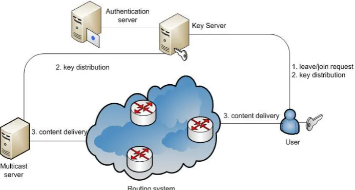
Key distribution centre (KDC) or server is responsible for authentication of a
user interested in joining the group. Server authenticates the user and allocates
location to newly joined user. Server also provides the necessary keys to the
user, which enables this user to communicate within the group.
Key management protocols are responsible for key pre-distribution and key
updating in case of changes in the group. Group keys are shared among all the
members and the contents to be shared are encrypted with this key and
broadcasted to all group members. Such groups are supposed to be flexible
enough to allow new hosts to join and present members to leave. Joining and
leaving of hosts require change in the group key, so that the privacy and
secrecy of the group members and their communication can be preserved.
Figure 1-1 shows structure of a secure centralized multicast system.
3
To maintain group keys, secure key management protocols are devised and
employed. These protocols provide the authentication services, along with
changing of the group keys with each user joining and leaving. The process of
changing keys on every user join or leave is called key updating or rekeying.
Lack of presence of any key management protocol has rekeying cost of nK
for n users. Logical key hierarchy (LKH) [5] and one-way function key tree
(OFT) [1] are two much efficient centralized key management schemes. These
both schemes differ in their functionalities; OFT follows down-up strategy as
opposed to LKH which follows a static key tree structure. LKH has broadcast
costs of 2hkh for n users, where k is key size in bits and h is the height of
tree. OFT scheme includes users along with the server in key updating process.
This makes the scheme more efficient and it cuts the overhead cost at
rekeying by 1 / 2 , i.e., hkh.
1.2
Security Requirements
Centralized key management schemes must, in all conditions, fulfill some
security requirements. Their basic security requirements are forward and
backward secrecy in the group. Security requirements are discussed in detail
in Chapter 2.
Forward Secrecy: Evicted members of the group are unable to access new
information in the group, which states they cannot compute (or access) newer
4
Backward Secrecy: New members of the group are unable to access previous
information in the group, which states that they cannot compute older group
keys.
1.3
Objectives
To fill the security gap caused by collusion attacks on OFT and to reduce
comparatively higher cost of LKH scheme, several improvements in both of
these key management schemes have been proposed in this thesis.
OFT scheme is found to be weak against attacks by adversaries. We propose
an improved OFT scheme, which guarantees better security at minimum costs.
We also propose a simple LKH scheme for key distribution which provides
the same functionalities at lower transmission cost.
5
2
Key Management Schemes
This chapter describes two main centralized key management schemes in
detail; logical key hierarchy and one-way function key tree. This chapter also
covers collusion attacks on OFT scheme and revisited security requirements
for key management schemes.
2.1
Logical Key Hierarchy
LKH maps all members of the group as leaves of a structured tree, most
commonly as a balanced binary tree. Group key is at the root of the tree,
whereas the leaves represent group members. Group members have to store
their individual keys, group key, and all node keys in the path from member to
the group key.
Figure 2-1 shows a balanced binary LKH key tree with height h3. If the
number of users in the group isn, then height of group is given as hlog2n.
On each user leave or join, group key and other node keys in the path must be
changed. New group key can be distributed by following the algorithms for
join and leave functions, which will be defined in next subsections.
The complexity for key distribution ton users will be O(logn).
2.1.1
LKH Tree Structure
All users in the group store log2n1 keys, out of which one is their
individual key and all other h keys belong to the middle nodes in its path to
the group node key. These h keys with the user need to be changed after each
6
Figure 2-1 Logical key tree.
2.1.2 On User Join
Suppose user u8 joins the group and users u1 to u7are the present members.
The group key k and two node keys k78 and k58 are changed to k', k' ,78
and k' ,58 respectively.
The key distribution process for each user join can be listed as:
1. Server authenticates the interested user u8 and allocates it an empty
place in the group tree. Server also provides individual key k8to the
new user.
2. All the keys which u8 needs in order to communicate with group
members, i.e., k', k' ,78 and k'58 are sent by unicast to u8 encrypted
7
3. k'78 is shared by unicast to the sibling of new user u8, u7,after
encrypting with its individual key k7.
4. k'58 is transmitted by multicast to u7 and (u u5, 6)encrypted with
78
'
k and k56, respectively.
5. New group key k' is sent by multicast to (u u u5, 6, 7) and
1 2 3 4
( ,u u u u, , ) after being encrypted with k'58 and k14,respectively.
2.1.3 On User Leave
On eviction of user, middle node keys must be changed to preserve
communication secrecy in the group.
Suppose user u8 leaves the group. Here, the group key kand node key k58
must be changed. Their new values can be represented as k' and k' ,57
respectively.
1. User u8 node is deleted from the key tree at first.
2. User u8 sibling’s node, u7,moves to its parent’s node.
3. k58 and k are updated to new values, 'k and k' ,57 respectively.
These new values are then sent to users u7, (u u5, 6), and
1 2 3 4
( ,u u u u, , ) by encrypting them with keys k7, k56, and k14,
8
2.2
One-Way Function Key Tree
OFT key management scheme decreases server-level computation, as
computation load is distributed between the server and group members.
Rekeying overhead for OFT is hkh.
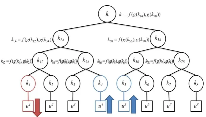
Figure 2-2 shows OFT key management scheme, where f a b( , )is a mixing
function and g(.) a one-way hash function. The value of g(.) is called
blinded node key.
Details of these functions are as follows.
• One-way function,
g
( )
: The keys are passed through a strongone-way function to hide the contents of the original key. These “blinded”
keys can be shared to corresponding users without any security
concerns.
• Joining function,
f a b
( , )
: This function concatenates or combinestwo entities,
a
and b.9
Members can calculate desired key ki by following formula
( ) ( )
( ( ), ( ))
i left i right i
k f g k g k
where kleft i( )and kright i( )denote left and right children node keys of the node
key ki.
2.2.1 OFT Structure
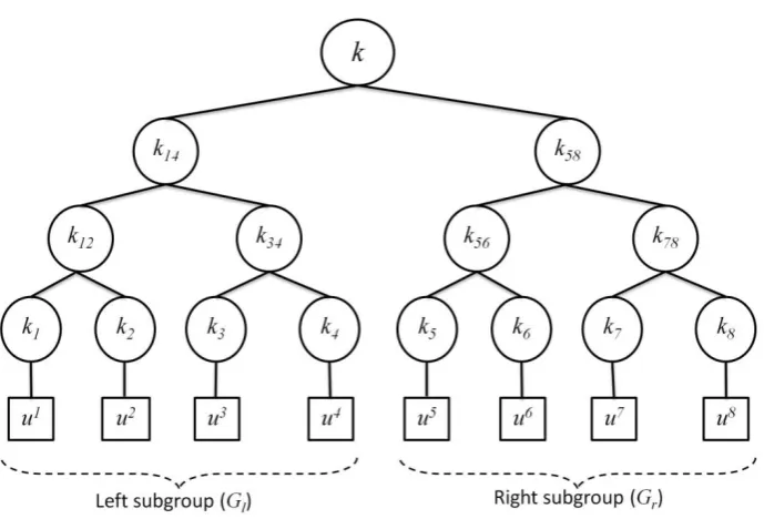
In OFT, keys are dependent on each other. Group members have knowledge
of certain blinded node keys, which enables them to generate new keys on
every user join and leave. All members know their sibling’s blinded node key
as well as their ancestors’ sibling’s blinded node keys. For example, user u1
also storesg k( 2), g k( 34),and g k( 58)along with its individual key k1. Now,
members can compute their node keys and more importantly, the group key
by using these known values. Left subgroup with users ( ,u u u u1 2, 3, 4)
performs the following operations to find their node keys as
12 1 2
34 3 4
14 12 34
( ( ), ( )) ( ( ), ( )) ( ( ), ( )).
k f g k g k k f g k g k k f g k g k
Blinded subgroup node keyk14, which is left child node of group key, is
shared with other subgroup. Users (u u u u5, 6, 7, 8) can compute key for right
child node of group key, which is then shared with neighboring left subgroup
10
56 5 6
78 7 8
58 56 78
( ( ), ( )) ( ( ), ( )) ( ( ), ( )).
k f g k g k k f g k g k k f g k g k
Group keykcan be generated by all members of the group as
14 58
( ( ), ( )).
k f g k g k
Here, server as well as all group users participates to compute the group key.
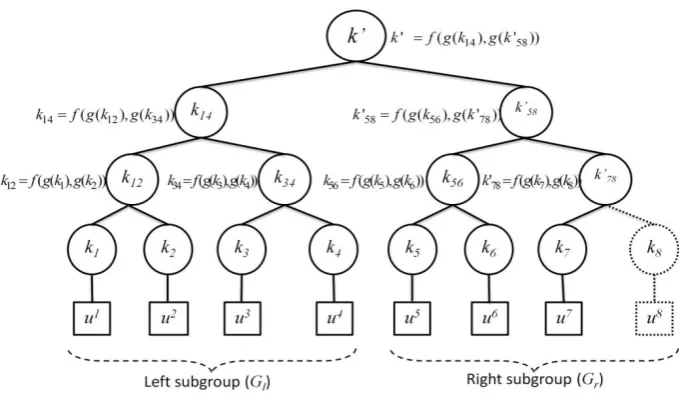
2.2.2 On User Join
Figure 2-2 shows the case of use joining, where a new user has just entered
the group. When a user, say u8, joins the group, he will receive his sibling’s
blinded node key g k( 7), and his ancestors’ sibling blinded node keys, g k( 56)
and g k( 14). Server unicasts these keys to u8 after encrypting them with
individual key of u8, k8. On the other hand, u8 calculates k'78, k' ,58 and 'k
by using the following formulae
78 7 8
58 56 78
14 58
' ( ( ), ( ))
' ( ( ), ( ' ))
' ( ( ), ( ' )).
k f g k g k
k f g k g k
k f g k g k
The blinded values of the calculated keys are encrypted with their sibling keys
and advertised to existing group members by multicast as follows:
1 4 58 14 5 6 78 56 7 8 7 ~ :{ ( ' )}
and :{ ( ' )}
:{ ( )}
multicast
u u g k k
server u u g k k
u g k k
11
2.2.3 On User Leave
On every user leave, group key must be changed to preserve forward and
backward secrecy. The sibling of the evicted user is assigned with new key
and it moves up to their parent’s node. The group key alters because of these
steps.
Suppose user u8 leaves the group. Group key k'and node key k'58 are
computed by members of the group by using blinded node keys given as
58 56 7
14 58
' ( ( ), ( ' )) ' ( ( ), ( ' )).
k f g k g k k f g k g k
Updated right subgroup key k'58 is shared with complementary left subgroup,
whose members can calculate the new group key.
By using this procedure, the need of multicasting all updated keys is reduced,
as the users can compute necessary keys themselves. Only few blinded node
keys are sent to particular users and subgroups. OFT reduces the required
broadcasts to nearly half as compared to LKH scheme.
2.3
Collusion Attacks on OFT
2.3.1 Horng’s Attack
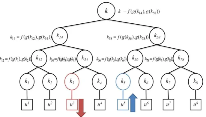
Horng [6] shows that OFT scheme is susceptible to collusion attacks, where
leaving and joining users can collude their information of group keys to find
older or newer group keys as shown in Figure 2-3. This weakens the security
notions of forward and backward secrecy.
12
Figure 2-3 User u3 is leaving the group and user u5 joins the group.
Suppose the initial group key to be kt0given as
0 ( ( 14), ( 58)).
t
k f g k g k
In Figure 2-3, user u3 leaves the group. This causes the group key to be
changed. New group key kt1will be
1 ( ( ' ), (14 58)). t
k f g k g k
If there is no other key updating operation and user u5joins the group, then
new group key kt2will be
2 ( ( ' ), ( ' )).14 58 t
k f g k g k
User u3 knows the value g k( 58) and user u5 has knowledge of g k( ' )14 . Both
users can collude their information to form kt1 as kt1 f g k( ( ' ), (14 g k58)).
OFT scheme is unsuccessful to provide forward secrecy against u3and
13
2.3.2 Ku and Chen’s Attack
Ku and Chen [10] present some other cases of collusion attacks on OFT. We
present these conditions here.
Figure 2-4 User u1 leaves the group and users u4 and u5 join the group.
Consider Figure 2-4 for these attacks. Alice is represented by user u1 in the
group; Bob is associated with user u4 in the key tree; Candy is related to user
u5. Also, time intervals follow the relation t3 > t2 > t1.
If Alice is evicted at state t1 and Bob is added to the same subgroup at time t2,
they can collude to get the value of Gl subgroup key between time intervals t1
and t2, as observed in Horng’s attack. As both members also know the blinded
node key of subgroup Gr, they can easily compute group key between time
intervals t1 and t2. Also, consider that Alice leaves the group at time t1.
After this, Bob joins the group at time t2 , whereas Candy joins the group at
14
Alice and Bob are associated with Gl, whereas Candy belongs to Gr. Here,
Alice knows the blinded node key of subgroup Gr between times t1 and t3.
Candy knows the blinded node key of subgroup Gl between time t2 and t3.
Alice and Candy can share their information about blinded node keys of
subgroups to compute group key between time t2 and t3.
In both of these cases, successful collusion attacks occur, which compromise
the security of group communication. OFT scheme has security vulnerabilities,
which must be addressed.
2.4
Security Requirements
Now we list some security requirements which must be fulfilled by all key
management schemes in order to ensure secure communication in dynamic
multicast systems.
1.
Group key secrecy:
Any passive adversary is unable in any way to compute previous or existing group key. This also implies thatadversary is also unable to find any changed node key in the group.
Mathematical operations and random numbers involved in rekeying
must be cryptographically strong.
2.
Forward key secrecy
:
Passive adversaries or former members of the group, who may know any subset of older group keys, cannotfind any new group key.
3.
Backward key secrecy
:
Passive adversaries or present members of the group, who may know any subset of group keys, are unable to15
4.
Key independence
: Passive adversaries or former and present members of the group, who may know any subset of group keys, areunable to discover any other group key.
5.
Reuse of known node keys
:
Evicted members must not discover any new information that is flowing within the group. Sometimesevicted users can use their prior knowledge of node keys to decrypt
any future transmission. All node keys known to a leaving member
must be changed during rekeying process.
6.
OFT group key segments
:
Group key in OFT scheme is combination of blinded node keys of its two children. These twochildren nodes represent left and right subgroup node keys. For each
user leave, both segments of the group key must be changed. This
16
3
New Secure OFT Scheme
In this chapter, improvement in the OFT schemes will be introduced, that is,
OFT scheme is vulnerable to collusion attacks and thus this scheme needs
extra steps to make it reliable enough for proper functionalities.
We propose new OFT scheme with more security and lesser costs.
3.1
Introduction
In OFT scheme, all members are given the blinded node keys of their siblings
and their ancestors’ siblings. They can then calculate the desired node and
group keys by using these blinded node keys. In this way, a part of
computation load is transferred to the users from the server. In OFT, rekeying
overhead decreases as a result of combined computations by the server and
members.
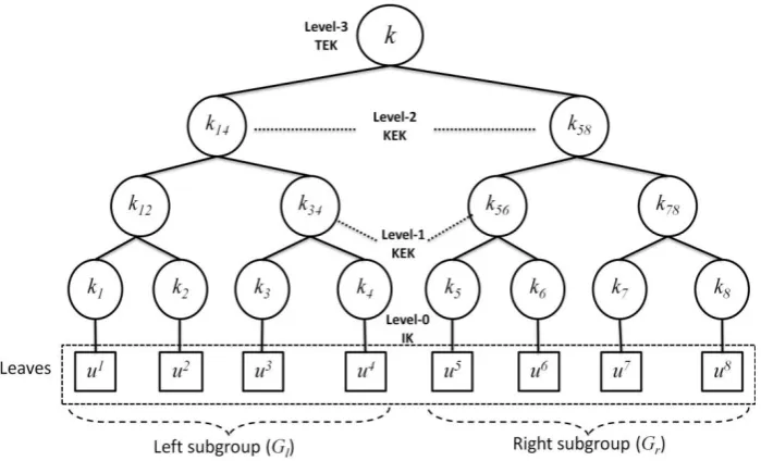
First we define the levels and locations of the members in the group. Figure
3-1 shows how we name each user based on their level and location within
level in the group. This will help us in introducing the scheme which provides
better key management performance along with ensuring better security
17
Figure 3-1 Key tree with levels.
In the above figure,
• TEK: traffic encryption key (group key), used for communicating
with all the users in the group (highest level node key)
• KEK: key encryption keys, also called as sub-group keys. They are
used for encrypting the group key for its transfer (intermediate level
node keys).
• IK: Individual keys of users (lowest level node keys)
• Height of tree (h): Number of levels in the tree. For example, the
18
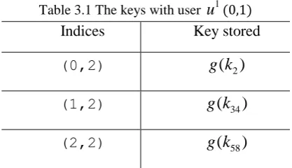
Figure 3-2 Key tree with location indices.
We provide all the users with location indices which give information about
their level and location in the group. Users must have log2n blinded node
keys, which are the blinded node keys of their siblings and their ancestors’
siblings, to communicate within group and update the keys whenever needed.
These blinded node keys are kept with their indices, in the user’s memory as
shown in Figure 3-2. This helps in maintaining and updating these keys
whenever there is some change in the group.
19
Table 3.1 The keys with user
u
1(0,1)Indices Key stored
(0,2)
g k
( )
2(1,2)
g k
(
34)
(2,2)
g k
(
58)
Similarly, other users have the blinded node keys stored with the same
pattern.
Our scheme performs only at user eviction. On user join, it follows the
scheme of original OFT.
3.2
On User Leave
In case of eviction, the sibling of the removed user takes the place of their
parent. Also its sibling key changes, which causes change in the node key
and the group key. Figure 3-2 shows eviction of u8 after which u7promotes
to a higher level. Shaded nodes are the ones to be altered.
3.2.1 Key Requirements
Node keys are dependent in OFT scheme and users contribute in generation
of node keys. Users have blinded node keys of their siblings and parent’s
siblings, which are used to efficiently generate new keys without much
intervention from server. Group members update the keys present with them
and generate new node keys and the group key. New keys can be generated
20
3.2.2 Algorithm on User Eviction
We present the algorithm which is followed by our scheme at user eviction.
1. Server removes the node of evicted member from the key tree and
promotes its sibling, if any, to higher level which was the level of
its parent before eviction.
2. Server provides new node key to evicted member’s sibling. It also
shares the changed blinded node keys with appropriate neighboring
members.
3. All members of the affected subgroup can compute new subgroup
node key.
4. Server shares this new subgroup node key in blinded form with
neighboring unaffected subgroup members.
5. For the unaffected subgroup, server generates and shares a random
number with its members.
6. Members update stored node keys by XORing them with the
provided random number, after which the resulting values are
passed through one-way function to generate new node keys.
7. All members of unaffected subgroup can calculate new subgroup
node key by utilizing one-way and combining functions on blinded
node key.
8. This new subgroup node key is then shared with the neighboring
(unaffected) subgroup.
21
and unaffected subgroup to calculate new group key.
3.2.3 An Example of User Eviction
User u8leaves the subgroup with users u u u5, 6, 7, and we define this
subgroup as right, Gr. The other subgroup is defined as left subgroup, Gl.
Group key is combination function of blinded node keys of subgroups Gr
and Gl . Our protocol changes both of these subgroup keys in order to
prevent collusion attacks.
1. After removal of u8, k7changes and this affects the node keys,
which changes to k'57and 'k . The new blinded node key g k( ' )7 is
shared with the neighboring subgroup (u u5, 6) by encrypting with
their node key k56as
u5 and u6:{ ( ' )}g k 7 k56.
2. Subgroup key k'57can be formed by
57 7 56
' ( ( ' ), ( )).
k f g k g k
3. Right subgroup key is shared with the other subgroup as
57 14
:{ ( ' )} .
s
G g k k
4. Level-2 blinded subgroup node key is transmitted to the left
subgroup members, encrypted with their blinded subgroup node
key as
58 14
:{ ( ' )} .
s
G g k k
5. As for the left subgroup, server generates a random number rn,
which is shared between all the present users of the subgroup as
14
:{ } .
s n
22
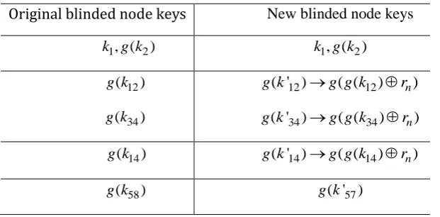
6. Users can change the blinded node keys with them, so as to alter
the overall left blinded subgroup node keys. Already available
blinded node keys can be changed like as shown in Table 3.2.
Table 3.2 Blinded node key change operations for user u1(0,1) Original blinded node keys New blinded node keys
k g k1, ( 2) k g k1, ( 2)
12 ( ) g k 34 ( ) g k 12 12
( ' ) ( ( ) n)
g k g g k r
34 34
( ' ) ( ( ) n)
g k g g k r
14
( )
g k g k( ' )14 g g k( ( 14)rn)
58
( )
g k g k( ' )57
7. New node key can be formed by all left subgroup users as shown in
Table 3.2.
14 14
( ' ) ( ( ) n)
g k g g k r
8. This level-2 blinded subgroup node key is transmitted to the right
subgroup members, encrypted with their blinded subgroup node
key as
14 58
:{ ( ' )} ' .
p
G g k k
9. New group key k can be computed by all members of the group
by using
14 58
23
3.3
Simulation and Results
Results of our proposed scheme and the conventional key management
schemes are shown in this section.
Table 3.3 shows security properties of some of the known schemes, and
shows that our proposed scheme has got better security strength.
Table 3.3 Security of key management schemes
Schemes
Secrecy Secure against collusion attacks Forward Backward
Simple Y Y Y
GKMP [4] N Y Y
LKH [9] Y Y Y
OFT [7] N N N
Ku and Chen [10] Y Y Y
Xu et al. [11] Y Y Y
Proposed sol. Y Y Y
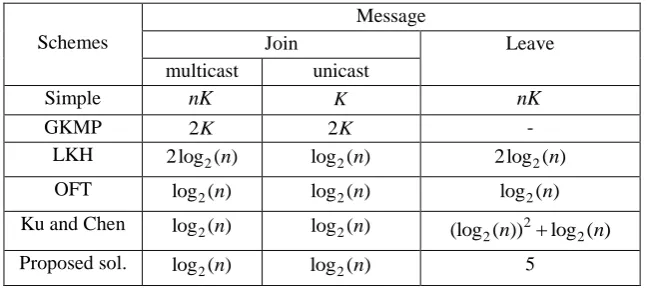
Tables 3.4 and 3.5 show performance of various schemes. They show that
our scheme has less broadcast costs for user leave, as compared to scheme
by Ku and Chen [10]. Our scheme performs even more efficiently than OFT
for large group sizes.
Table 3.4 Performance comparison of key management schemes
Schemes
Message
Join Leave
multicast unicast
Simple nK K nK
GKMP 2K 2K
-LKH 2log ( )2 n log ( )2 n 2log ( )2 n
OFT log ( )2 n log ( )2 n log ( )2 n
24
Table 3.5Encryption costs for different schemes
Schemes Join Leave
LKH 3log ( )2 n 2log ( )2 n
OFT 2log ( ) 22 n log ( )2 n
Ku and Chen 2log ( ) 22 n 2
2 2
(log ( ))n log ( )n
Proposed sol. 2log ( ) 22 n 5
3.4
Security Analysis of Proposed Scheme
Possibility of collusion attacks in OFT scheme arises because OFT keeps
the blinded node keys known to the evicted members intact. Evicted
members can then share blinded node keys available with them with other
users in order to get the group key information which they are not intended
to know.
The proposed scheme, on the other hand, amends this vulnerability, that is,
blinded subgroup node keys known to the evicted members are changed. In
the proposed schemes, the former members are not able to reconstruct group
keys by exercising any attacks explained in this paper.
An example of a typical case of member eviction is given here. Alice evicts
the subgroup Gl, after which Bob and Candy join the subgroup Gl or Gr.
Alice knows the initial group key
0
( ) ( ( l), ( r))
G s G G
k f g k g k .
25
Case 1:
Consider the case when both Bob and Candy join same subgroup,Gr.
Then, we can write group key kG at different steps as follows.
Step 1: Alice evicts Gl
1
( ) ( ( l), ( r))
G s G G
k f g k g k .
Step 2: Bob joins Gr
2
( ) ( ( l), ( r))
G s G G
k f g k g k .
Step 3: Candy joins Gr
3
( ) ( ( l), ( r))
G s G G
k f g k g k .
As obvious in this case, Alice is not able to collude with any present
member in order to find illegitimate group keys.
Case 2:
Consider the case when Bob joins subgroup Gl, whereas Candy joins the
subgroupGr.
Then, we can write group key kG at different steps as follows.
Step 1: Alice evicts Gl
1
( ) ( ( l), ( r))
G s G G
k f g k g k .
Step 2: Bob joins Gl
2
( ) ( ( l), ( r))
G s G G
k f g k g k .
26
3
( ) ( ( l), ( r))
G s G G
k f g k g k .
As seen in this case also, Alice is not able to collude with present members
in order to find illegitimate group keys.
27
4
Multicast Scheme Based on LKH
In this chapter, we will provide a new scheme based on LKH. Our proposed
scheme is more efficient than the original LKH scheme in terms of
communication overheads needed at rekeying.
4.1
System Design
4.1.1 Design Principles
Firstly, we outline some basic principles, which our proposed scheme will
comply. We use binary key tree, which tends to balance itself in order to
maintain the symmetry. Interested hosts can join the group through a process
which includes sending request to the server and passing the authentication by
the server.
Server provides an empty place on the group to the new users. Server also
provides the new member with all the necessary keys through the key
management protocol. Similarly, present members can leave the group by
sending request to the server, who in return eradicates the user and its
corresponding node from the key tree. Sibling of the leaving node moves to
the position of their parent node.
4.1.2 Detailed Outline
On each join or leave, keys in the path from that location to server need to be
28
secure group communication. Server changes log2nkeys for each join, and
2
log n1 keys for each user leave.
The keys, which intend to be changed, affects 2lusers, where lis the level of
the key. This calls for an efficient protocol, capable of sharing new keys
among all members of the group.
Figure 4-1 shows a binary key tree with l3. On a user join, as shown in the
figure, log2nkeys, namely,k , k58,and k78are affected. Change of k78will
affect two users u7and u8. Similarly, changing subgroup key k58affects four
usersu5~u8.
Each group member needs to change its group key k , on every user join and
leave.
29
Our proposed scheme possesses the following distinctive features while
distributing keys for right subgroup.
• Our scheme follows bottom-to-top approach, where bottom node keys are
firstly distributed to the desired members, moving upwards.
• Higher level node keys are encrypted with lower level ones, and multicast
to subsequent subgroups. For example, subgroup key at level-1 will be
distributed by encrypting it with individual keys at level-0. After that, a
subgroup key at level-2 is encrypted with level-1 key before multicast,
and so on.
• Instead of wasting resources by sending all keys to only one user, our
proposed scheme moves in a step-wise manner thus providing all
essential keys to members.
4.2
On User Join
After the interested host is successfully authenticated, server allocates the host
an empty location in the group. Group key tree is renewed, according to
following protocol. Example protocol for height h3is described below,
which will be generalized afterwards. Figure 4-1 refers to the key tree for join
case.
8
u joins the group, forming a subgroup with u7. The shaded keys in the figure
are changed to new ones by the server.
4.2.1 Key Requirements
Depending on their location in the group, members require different keys to
30
1 8
5 6 7 8
58
~ : '
, , , : '
u u k
u u u u k
u7and u8: k' .78
'
k ,k' ,58 and k'78are new group key and subgroup keys, respectively.
4.2.2 Protocol for User Join
To share keys among the members of the group, they are encrypted by
individual or subgroup keys and sent through unicast or multicast to
respective members.
{ }k kijrepresents encryption of the group key kby any subgroup key kij. The
same notation is used in describing the schemes.
The protocol for key management on user join is given below, where the keys
are being transmitted by the server to various locations.
1. Server encrypts new group key k' with subgroup key k14 and
multicasts it to left subgroup as
1 4
14
~ :{ '} .
u u k k
2. For right subgroup, key distribution starts at the bottom where the
bottom-most node key k'78is encrypted with individual keys of both
users u7and u8, before being unicast to them as
7 78 7 8 78 8 :{ ' } :{ ' } .
u k k
u k k
3. Level-2 node key k'58is encrypted with level-1 node keys k56and
78
'
31
5 6
58 56
7 8
58 78
and :{ ' }
and :{ ' } ' .
u u k k
u u k k
4. Right subgroup gets its new group key k' by encrypting and
multicasting it as
4 8
58
~ :{ '} ' .
u u k k
4.3
On User Leave
User leave makes an empty slot in the binary balanced key tree. Sibling of the
leaving user gets promoted to the position of its parent’s node.
Figure 4-2 shows user u8leaving the tree, after which user u7resides on
level-1. Shaded nodes show the compromised keys that will be changed by
the server.
32
4.3.1 Key Requirements
For each user leave, server generates and shares
log
2n
1
keys to remainingmembers. The demand for keys differs with the member’s location. Keys
needed for update can be outlined as
1 7
5 6 7
57
~ : '
, , : '
u u k
u u u k
where 'k andk'57are new group key and subgroup key, respectively.
4.3.2 Protocol for User Leave
Less number of keys is shared on each user leave, contrary to the number of
keys distributed for each user join.
The protocol for key management on each user leave is described below,
where the keys are being transmitted by the server to various locations
encrypted by either individual or subgroup keys.
1. Server encrypts new group key k' with subgroup key k14 and
multicasts it to left subgroup as
1 4
14
~ :{ '} .
u u k k
2. As for right subgroup, key distribution starts at the bottom. Level-2
node key k'57is encrypted with node key k56and individual key of
user u7,k7, before being multicast and unicast, respectively.
5 6
57 56
7
57 7
and :{ ' }
:{ ' }
u u k k
u k k
3. Right subgroup gets its new group key k' by encrypting and
33
4 7
57
~ :{ '} ' .
u u k k
4.4
Simulation and Results
Performance of our proposed scheme as compared to LKH scheme is shown
in this section.
4.4.1 Performance Comparison
Tables 4.1 and 4.2 show performance of various schemes. They show that our
scheme has less broadcast costs for user leave and join as compared to other
key management schemes. Our scheme performs more efficiently than LKH
and the communication overhead of our scheme is less than that of LKH.
Table 4.1 Performance comparison of hierarchical schemes
Schemes
Message
Join Leave
Multicast Unicast
Simple nK K nK
GKMP 2K 2K
-LKH 2log ( )2 n log ( )2 n 2log ( )2 n
Our solution log ( )2 n log ( ) 12 n log ( ) 12 n
Encryption cost of our proposed scheme is also less than the original LKH
scheme.
Table 4.2Encryption costs for different schemes
Schemes Join Leave
LKH 3log ( )2 n 2log ( )2 n
34
4.4.2 Empirical Analysis
Following table shows broadcast costs at user join and leave for LKH and our
scheme. The improvement in results can be analyzed from the table.
Table 4.3 shows that our scheme has less broadcast costs for user join and
leave, as compared to LKH. Thus, our scheme is more efficient than LKH in
terms of costs.
Table 4.3Broadcast costs of schemes
Schemes Height
LKH Our solution
Join Leave Join Leave
10 30 20 20 18
12 36 24 24 22
13 39 26 26 24
14 42 28 28 26
15 45 30 30 28
16 48 32 32 30
17 51 34 34 32
18 54 36 36 34
Table 4.4 compares our proposed scheme at user join and leave with original
LKH scheme. It is clear that even for large groups, our proposed scheme gives
better overhead costs.
Table 4.4Comparison of our solution Height
Our sol./LKH
10 12 13 14 15 16 17 18
Join 0.67 0.67 0.67 0.67 0.67 0.67 0.67 0.67
Leave 0.9 0.917 0.923 0.928 0.933 0.9375 0.941 0.944
Following Figures 4-3 and 4-4 show the performance comparison of our
35
The following figures also show that our proposed scheme performs better
with different number of users.
Figure 4-3 Comparison between the proposed scheme and LKH on user join.
36
5
Conclusion
Key management in dynamic groups, where users can leave or join at their
ease is an important part of secure communication. Different strategies have
been proposed during last decade that aim to either improve the security or the
performance of key management schemes. Decreasing the encryption and
transmission overheads has also been a major concern for such schemes.
In this thesis, we proposed two schemes based on different architectures. One
of the schemes improves the security of OFT scheme. We showed the
resilience of proposed scheme by analyzing different cases. The other
proposed scheme improves the performance of independent key hierarchy
system (LKH).
Both proposed schemes provide better broadcast and transmission costs than
37
Bibliography
[1] D. Balenson, D. McGrew, and A. Sherman, “Key management for large
dynamic groups: One-way functions trees and amortized initialization,” IETF
Internet Draft, 1999.
[2] R. Canetti and B. Pinkas, “A taxonomy of multicast security issues,” IETF
Internet Draft, 1998
[3] R. Canetti, J. Garey, G. Itkis, D. Micciancio, M. Naor, and B. Pinkas,
“Multicast security: A taxonomy and efficient constructions,” Proceedings of
IEEE Infocomm'99, vol. 2, pp. 708-716, Mar. 1999.
[4] H. Harney, C. Muckenhirn, and T. Rivers, “Group key management
protocol architecture,” IETF, RFC2093, 1997.
[5] H. Harney and E. Harder, “Logical key hierarchy protocol,”
draft-harney-sparta-lkhp-sec-00.txt, IETF Internet Draft, 1999.
[6] G. Horng, “Cryptanalysis of a key management scheme for secure
multicast communications” IEICE Trans. Commun., vol. E85-B, no. 5, pp.
1050–1051, 2002.
[7] D. McGrew, A. David, T. Alan, and A. Sherman, “Key establishment in
large dynamic groups using one-way function trees,” TIS Report no.0755, TIS
Labs at Network Associates, Inc., Glenwood, MD, 1998.
[8] U. Varshney, “Multicast over wireless networks,” Commun. ACM, vol. 45,
38
[9] D. Wallner, E. Harder, and R. Agee, “Key management for multicast: Issues and architectures,” IETF, RFC2627, 1999.
[10] Wei-Chi Ku and Shuai-Min Chen,” An improved key management
scheme for large dynamic groups using one-way function trees,” Proc. ICPPW’03, pp 391-396, Oct. 2003.
[11] Xuxin Xu, Lingyu Wang, Amr Youssef, and Bo Zhu, ”Preventing
collusion attacks on the one-way function tree (OFT) scheme,” ACNS ’07
Proceedingsof the 5th International Conference on AppliedCryptography and
Network Security Springer-VerlagBerlin, Heidelberg, 2007.
[12] S. Rafaeli and D. Hutchison, “A survey of key management for secure group communication,” ACMComputing Surveys, Volume 35 Issue 3, Sept.