Issue 1
AMBIENT LEVEL CONTROLLER
V-5335621
by
PagePac
®INTRODUCTION
The Ambient Level Controller (ALC) constantly monitors room noise and adjusts the paging level to accommodate for any changes in noise level. It has a built-in Sound Pressure Level (SPL) meter.
SPECIFICATIONS
The ALC has two inputs, a loop start input (Telco) and a balanced 600 Ohm line input. The Telco input shall have priority over the line input. The microphone can be placed up to 5000 feet from the ALC with shielded wire. The ALC
has five contact closure clock or remote control inputs. The ALC has four double throw relay outputs that activate on the -6 dB and 0 dB levels.
The ALC adjusts page system level in 6 dB steps. The Telco input is loop start and has priority over the line input. The line input has a dry contact closure which will provide an isolated dry contact closure at the connections of the line output.
• Power consumption 60 Watts
• Frequency Response 250 Hz to 15 KHz + 2dB
• Signal to noise (dB ref.) Better than -60dB
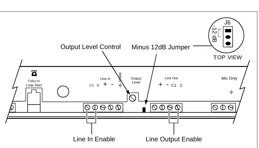
• Maximum output level 0dB, -12dB with jumper installed
• Output relay activaltion points 0dB and -6dB gain reduction
• Output relay contact rating 1 Amp
• Number of relay output contacts 4
• Input level controls (internal) 5
• Control requirements Dry contact closure
• Input types Line, Telco (loop start only)
• Output types Line (600 Ohm)
• Contact closure on output Yes
• Contact closure controlled input Yes
• Front panel controls Attenuation manual or automatic
• Front panel indicators Power
Attenuation, automatic Telephone input active
FEATURES
• Allows automatic, manual or remote control of paging system audio levels • SPL meter with over 50 dB range built-in
• Microphone can be placed up to 5000 feet from unit • Balanced 600 Ohm inputs and outputs
• Loop Start Telco input with priority over line input
• Clock contact closure or remote control input connections • Relay outputs for emergency override or indicators
• Dry contact closure on line input activates isolated dry contact closure on line output
• Internal microprocessor senses ambient noise via a MIC input, and adjusts the paging level accordingly
• Rack or wall mount, single rack space
• 24VAC UL listed power supply, Part 15 (FCC) approved
Dimensions/Weight
• 17”W x 1.75”H x 8.75”D (19”W with rack ears) (43.18cm x 4.45cm x 22.23cm)
• 8 lbs. (3.63 kg)
Environmental/Humidity
• 32 to 104
°
F (0 to 40°
C)• 0 to 85% non-condensing
TECHNICAL ASSISTANCE
When calling, have a VOM and a telephone test set available and call from the job site.
Call (800) 782-5266 and ask for PagePac Technical Support, or call (540) 427-6000 for Valcom 24-hour Automated Support or visit our websites at http://www.pagepac.com and www.valcom.com.
Should repairs be necessary, attach a tag to the unit clearly stating company name, address, phone number, contact person, and the nature of the problem. Send the unit to:
Valcom, Inc. PagePac® Repair Dept.
INSTALLATION
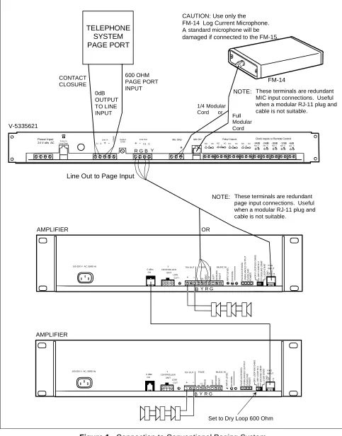
Figure 1. Connection to Conventional Paging System 100-250 V AC, 50/60 Hz
0 dBm OU T CO NTROLLER UNIT LOW
CUT - - C1 RIN
G
TI
P
70V OUT P AGE
DU CK IN G P A G E AC C E S SED UN B A L A N C E D O U T P UT O V ER L O AD PO W E R MUSIC IN DRY L O O P HI Z D R Y L OOP 6 0 0 OH M S G R O UND S TAR T L O O P ST AR T GN D RI N G TI P C1 PAG INPUT RI G H T LE F T GR OU N D IN P U T LE V E L + Power Input
24 V olts AC Loop StartTelco In
Line In
C1 G+
-Output Level
Line Out
+ - C1 C
Mic Only Mic Only
NOTE: These terminals are redundant MIC input connections. Useful when a modular RJ-11 plug and cable is not suitable.
CAUTION: Use only the FM-14 Log Current Microphone. A standard microphone will be
damaged if connected to the FM-15.
FM-14
V-5335621
AMPLIFIER
B Y R G
OR
R G B Y
Line Out to Page Input
600 OHM PAGE PORT INPUT S h ie ld
NOTE: These terminals are redundant page input connections. Useful when a modular RJ-11 plug and cable is not suitable.
Relay Outputs Clock Inputs or Remote Control
-24dB
NO C
1
-24dB
NO C
1
-18dB
NO C
1
-12dB
NO C
1
-6dB
NO C
1
NO 1C
NCNO 1CNCNO 1C
NC NO 1C
NC
100-250 V AC, 50/60 Hz
0 dBm OU T CO NTROLLER UNIT LOW
CUT - - C1 RI
N
G
70V OUT PAGE
DU CK IN G P A G E AC C E S SED UN B A L A N C E D O U T P UT O V ER L O AD PO W E R MUSIC IN DRY L O O P HI Z D R Y L O O P 60 0 O H M S GR OU N D S TAR T L O O P ST AR T GN D TI P C1 PAG INPUT RI G H T LE F T GR OU N D IN P U T LE V E L + AMPLIFIER
B Y R G
Set to Dry Loop 600 Ohm
TELEPHONE SYSTEM PAGE PORT CONTACT CLOSURE 0dB OUTPUT TO LINE INPUT 1/4 Modular Cord or
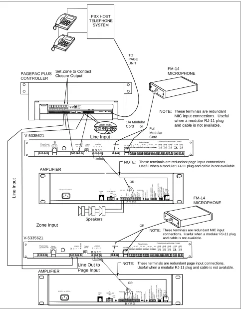
Figure 2. Multiple ALCs used with a Single Controller and Multiple Amplifiers
100-250 V AC, 50/60 Hz
0 dBm OU T CONTROLLER UNIT LOW
CUT - - C1RI
N
G
TI
P
70V OUT PAGE
DU CK IN G P A G E AC C E S SED UN B A L A NC E D O U T P UT O VER L O A D PO W E R MUSIC IN DR Y L O O P HI Z D RY LO O P 60 0 O H M S GR OU N D S TAR T L O O P ST AR T GN D RI N G TI P C1 PAG INPUT RI G H T LE F T GR OU N D IN PU T L E V E L +
100-250 V AC, 50/60 Hz
0 dBm OU T CONTROLLER UNIT LOW
CUT - - C1RI
N G TI P 70V OUT PAGE DU CK IN G P A G E AC C E SSE D U N B A L A N C E D O U T P UT O V ER L O AD PO W E R MUSIC IN DR Y L O O P HI Z D R Y LO O P 60 0 O H M S GR O U N D S TAR T LO O P ST AR T GN D RI N G TI P C1 P AG INPUT RI G H T LE F T GR O U N D IN PU T L EVE L + PBX HOST TELEPHONE SYSTEM V-5335621 AMPLIFIER Speakers PAGEPAC PLUS CONTROLLER FM-14 MICROPHONE FM-14 MICROPHONE
NOTE: These terminals are redundant page input connections. Useful when a modular RJ-11 plug and cable is not available.
OR
NOTE: These terminals are redundant page input connections. Useful when a modular RJ-11 plug and cable is not available.
OR
Set Zone to Contact Closure Output 0dbm 0dbu Li ne I npu t
Line Out to Page Input
V-5335621
AMPLIFIER
Line Input
Power Input
24 V olts AC Loop StartTelco In
Line In
+ - Output Level
Line Out
+ - C1 C
Mic Only Mic Only
Relay Outputs Clock Inputs or Remote Control
S
h
ie
ld
R G B Y
B Y R G
B Y R G
NOTE: These terminals are redundant
MIC input connections. Useful when a modular RJ-11 plug and cable is not available.
1/4 Modular Cord or
NOTE: These terminals are redundant MIC input connections. Useful when a modular RJ-11 plug and cable is not available.
OR
Zone Input
-24dB
NO C
1
-24dB
NO C
1
-18dB
NO C
1
-12dB
NO C
1
-6dB
NO C
1
NO 1C
NC NO 1CNC NO 1C
NC NO 1C NC TO PAGE UNIT Power Input
24 V olts ACLoop StartTelco In
Line In
C1 G+
-Output Level
Line Out
+ - C1 C
Mic Only Mic Only
Relay Outputs Clock Inputs or Remote Control
S
h
ie
ld
R G B Y
-24dB
NO C
1
-24dB
NO C
1
-18dB
NO C
1
-12dB
NO C
1
-6dB
NO C
1
NO 1C
NC NO 1CNC NO 1C
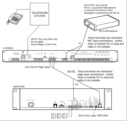
Figure 3. Connection between Paging Source and Amplifier 100-250 V AC, 50/60 Hz
0 dBm OU
T CONTROLLER
UNIT LOW
CUT - - C1 RIN
G
TI
P
70V OUT P AGE
DU
CK
IN
G
P
A
G
E
AC
C
E
S
SED
UN
B
A
L
A
N
C
E
D
O
U
T
P
UT
OV
E
R
L
O
A
D
PO
W
E
R
MUSIC IN
DRY
L
O
O
P
HI
Z
D
R
Y
L
O
O
P
60
0 O
H
M
S
G
R
O
UND
S
TAR
T
L
O
O
P
ST
AR
T
GN
D
RI
N
G
TI
P
C1
P AG INPUT
RI
G
H
T
LE
F
T
GR
OU
N
D
IN
P
U
T
L
E
VE
L
+ Power Input
24 V olts AC Loop StartTelco In
Line In
C1 G+
-Output Level
Line Out
+ - C1 C
Mic Only Mic Only Relay Outputs
Clock Inputs or Remote Control -24dB -24dB -18dB -12dB -6dB
NO C 1
NO C 1
NO C 1
NO C 1
NO C 1 NO 1 C NCNO 1C NCNO 1 CNCNO 1 CNC
CAUTION: Use only the FM-14 Log Current Microphone. A standard microphone will be
damaged if connected to the FM-15.
FM-14 Microphone
V-5335621
AMPLIFIER
OR
B Y R G
NOTE: These terminals are redundant page input connections. Useful when a modular RJ-11 plug and cable is not suitable.
OR
R G B Y
Line Out to Page Input NOTE: Dry Loop Start only. Do not apply
Ring Voltage or Dial Tone
S
h
ie
ld
TELEPHONE SYSTEM
These terminals are redundant MIC input connections. Useful when a modular RJ-11 plug and cable is not suitable.
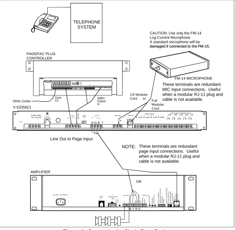
Figure 4. Connection for Single Zone Paging 100-250 V AC, 50/60 Hz
0 dBm OU
T CONTROLLER
UNIT LOW
CUT - - C1 RIN
G
TI
P
70V O UT P AGE
DU
C
K
IN
G
P
A
G
E
AC
C
E
S
SED
UN
B
A
L
A
N
C
E
D
O
U
T
P
UT
OV
E
R
LOA
D
PO
W
E
R
MUSIC IN
D
R
Y
LOOP
H
I Z
D
R
Y
LOOP
600 OH
M
S
GR
OU
N
D
S
TAR
T
L
O
O
P
ST
AR
T
GN
D
RI
N
G
TI
P
C1
P AG INPUT
RI
G
H
T
LE
F
T
GR
OU
N
D
IN
P
U
T
L
E
V
E
L
+ Power Input
24 V olts AC T elco In Loop Start
Line In C1 G+
-Output Level + - Line Out
C1 C
Mic Only Mic Only
Relay Outputs -24dB -24dB -18dB -12dB -6dBClock Inputs or Remote Control
NO C 1
NO C 1
NO C 1
NO C 1
NO C 1 NO
1 NO
1 NO
1 NO
1 CNC
CNC CNC
CNC
CAUTION: Use only the FM-14 Log Current Microphone. A standard microphone will be damaged if connected to the FM-15. damaged if connected to the FM-15.
FM-14 MICROPHONE
V-5335621
AMPLIFIER
B Y R G
NOTE: These terminals are redundant page input connections. Useful when a modular RJ-11 plug and cable is not available.
OR
R G B Y
Line Out to Page Input
S
h
ie
ld
Ser #
TELEPHONE SYSTEM
These terminals are redundant MIC input connections. Useful when a modular RJ-11 plug and cable is not available.
PAGEPAC PLUS CONTROLLER
Other Zones 0dBmOutput or Zone
CC
1/4 Modular Cord or
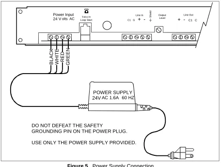
Figure 5. Power Supply Connection
Clock Control or Remote Control of Levels [Manual Override] (see Figure 6)
In the case where a user wishes to control the system level by the time of day, it is a simple matter with the ALC. Use a clock with four separate dry contact closures assigning each to a different time of day. So long as the contacts are closed the level selected will override the front panel controls. Should two contacts be closed at the same time the lower level selected will have priority. Also a manual normally open switch may be used to achieve this result.
Control of External Devices [Relay Outputs] (see Figure 6)
The ALC provides for control of external devices that need activation at maximum noise levels. This is provided by four sets of dry contact closures on the back panel. These activate at -6 and 0 dB levels. This can be used for priority override of remote level controls, strobe activation or similar applications.
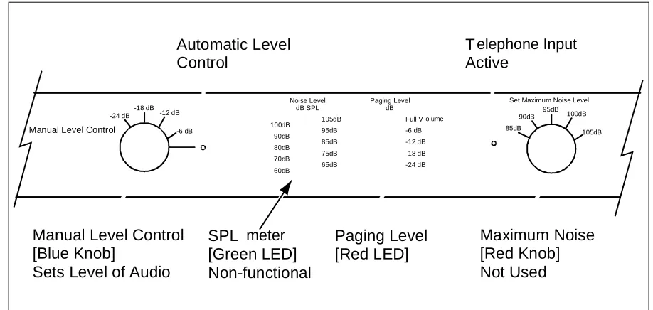
Set the manual level control to automatic [Blue knob] (see Figure 7). This allows the ALC to calibrate itself. The automatic position will allow the ALC to constantly change the paging level to compensate for the changes in noise level in the area being monitored.
Check the SPL meter [Green LED] (see Figure 7) for maximum noise level. This is your high noise level reading. Then set the maximum noise level control [Red knob] to the average high noise level. If you feel the room noise may actually be louder at some time, move the control up one click to the right [clockwise].
POWER SUPPLY 24VAC 1.6A 60 HZ
BL
AC
K
WH
IT
E
RE
D
G
R
EEN
Power Input
24 V olts AC Loop StartTelco In
Line In
C1 G +
-Output Level
Line Out
+ - C1 C
S
h
ie
ld
DO NOT DEFEAT THE SAFETY
GROUNDING PIN ON THE POWER PLUG.
The paging level meter [Red LED bar graph] (see Figure 7) indicates the paging level changes that are taking place with dual LEDs.
Calibration complete.
Figure 6. Clock Control or Remote Control of Levels Manual Override, Relay Outputs
Figure 7. Manual Level Control of the ALC without the Microphone & Remote Manual Level Control
-24dB -24dB -18dB -12dB -6dB
NO C 1
NO C 1
NO C 1
NO C 1
NO C 1 NO
1 C NC NO 1 C NC NO 1 C NC NO 1 C NC
Control of External Devices
Relay Outputs
Clock Control or Remote Control of Levels
Manual Override
Mic Only Mic Only
Relay Outputs Clock Inputs or Remote Control
100dB 90dB 80dB 70dB 60dB
105dB 95dB 85dB 75dB 65dB
Full Volume
-6 dB -12 dB -18 dB -24 dB Noise Level
dB SPL
Paging Level dB -18 dB
-24 dB -12 dB
-6 dB
Manual Level Control
95dB
90dB 100dB
105dB Set Maximum Noise Level
85dB
SPL meter [Green LED] Non-functional
Paging Level [Red LED]
Maximum Noise [Red Knob] Not Used Manual Level Control
[Blue Knob]
Sets Level of Audio
Automatic Level Control
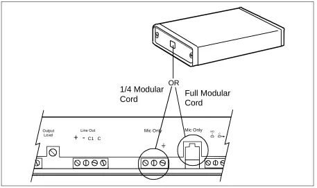
FM-14 Log Current Microphone (see Figure 8)
The wire for the FM-14 Log Current Microphone does not have to be shielded. This can be a phone line existing in the building. Use a RJ-11 connector at the microphone. When connecting the MIC, use a RJ-11 connector or wire directly to the terminal strip marked MIC ONLY.
Figure 8. Connection of the FM-14 Log Current Microphone
Manual Use of the Ambient Level Controller (see Figure 7)
The ALC may be used without the FM-14 MIC. In this mode the ALC becomes a leveler or limiter for a manual control of the sound system. The Telco input or the line input may be in this mode. The SPL meter will not function but all other functions will work in the normal way. The manual level control on the front panel will set the level of the sound system [Blue knob].
Output Level
Line Out
+ - C1 C
Mic Only Mic Only NO 1 C
OR
1/4 Modular
Microprocessor Update Timing Period (see Figure 9)
To change the microprocessor update period, remove the top cover, find the jumpers marked “Timing Adj. J4 and J5”, then refer to the chart below.
PERIOD J4 J5
0.5 Seconds IN OUT
1.0 Seconds OUT IN
2.0 Seconds OUT OUT
4.0 Seconds IN IN
Figure 9. Timing Adjustments for J4 and J5
Figure 10. Output Level Control
Line Output Enable Output Level Control Minus 12dB Jumper
J6
-12 d
B
TOP VIEW
Telco In Loop Start
Line In C1 G +
-Output Level
Line Out
+ - C1 C
Mic Only
S
h
ie
ld
Line In Enable
J5 J4 C14
C13
TIMING ADJ1
TIMING ADJ2 J9
Y1 R8
S3
R10
R11
C15
RP7 U11
RP8
C12
-24 VR5
-18