Design and Analysis of Progressive Tool for Photo Frame Hook
Mr.Sandeep P V Mr. C. Vikhnesh , ME MBA
ME, Manufacturing Engineering Assistant Professor
Dept.of mechanical Engineering Dept.of mechanical engineering
S.V.H.E.C - Gobi S.V.H.E.C - Gobi
Abstract
Design and development of progressive tools for the sheet metal component is one important phase in sheet metal manufacturing. Sheet metal press working process by progressive tools is a highly complex process that is vulnerable to various uncertainties such as variation in progressive tools geometry, stripe layout, die shear, material properties, component and press working equipment position error and process parameters related to its manufacturer. These uncertainties in combination can induce heavy manufacturing losses through premature die failure, final part geometric distortion and production risk. Identification of these uncertainties and quantifying them will facilitates a risk free manufacturing environment, which can be obtained by effective tool design.
This project aimed at designing and analyzing a progressive tool for photo frame hook with aid of computer aided design package. The design of the tool is intended both skilled and unskilled labour and mass production of the component, which is cost effective and consumes lesser time for production.
Keywords: Progressive tool, Strip layout, Press tonnage, Punching force, Analysis
1. Introduction
In sheet metal forming when dealing with complicated shapes the process sequence, die geometry, perform shape and process parameters at each stage are designed based on past experiences and trial and error. As a result die and process development may be time consuming and costly. Therefore a computer aided approach is highly desirable for designing robust process
sequence to reduce expense. A survey of literature suggest
that no theoretical or precise empirical relationship is available that can aid tool users in the rational selection of tool parameters resulting in minimum distortion of tool in operation.
In this investigative thesis work, an attempt has made to go through various design stages of a progressive tool and to conduct an analysis work to determine the safe
load, stresses and deflection for the same. Thereby trying to reduce the possible future failures of tool and hence to increase the efficiency of production.
2. Objective of the project work
The purpose of the present investigation is to study the manufacturing of sheet metals by use of a progressive tool. It is necessary to go through the various stages of designing and finding out the possible failures or errors that would happen at the time of manufacturing. In sheet metal forming when dealing with complicated shapes the process sequence, die geometry, perform shape and process parameters at each stage are designed based on past experiences and trial and error. As a result die and process development may be time consuming and costly. Therefore a computer aided approach is highly desirable for designing robust process sequence to reduce expense.
3. Tool Design for Photo Frame Hook
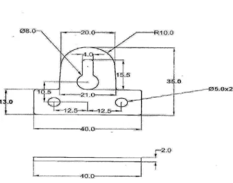
3.1 Component diagram
3.2 Component Analysis
Material : Mild Steel (S42)
Thickness : 2 mm
Shear strength : 35kg/mm2
Temper grade : Hard
Supply condition : Strips
Geometry tolerance : IS2102
3.3 Strip layout
Fig. 3.2 Scrap Strip Layout
3.4 Design Calculations for the Tool
Component Material = MS Thickness of the strip= 2mm
Component area = 1086.16
mm2
% of strip used = (Area of component) /(length of strip×width of strip
= (1086.16)/(37.5×44) = 0.6582
% of strip used = 0.6582×100 = 55.58 % Shear force =K L t Ssh /1000 tons
Where,
K is a constant = 1.1 to 1.5 (based on clearance) L = length of cut in mm
t = thickness of stock in mm
Ssh= shear strength of material Kg/mm2
Shear force = 1.5x211.95x2 x 40/1000 = 25.43 tons
Stripping force = 10% of shear force = 10x25.43/100 = 2.54 tons Total force = shear force + stripping force
= 25.43 +2.54 = 27.98 tons
Press tonnage = 1.2 x total force = 1.2x 27.98
= 33.57 tons.
Thickness of the die plate
(td) = 3√Fsh Fsh =shear
load in ton
td = 3√16.95 = 2.56cm = 25.6 mm Die thickness selected = 30mm Thickness of the punch holder = 0.5x td = 0.5x30 = 15mm Thickness of bottom plate (tb ) = 1.5xtd =1.5x30 = 45mm Thickness of top plate (tp) =1.25xtd =1.25x30 = 37.5mm
Thickness of stripper plate (ts) = 0.5xtd = 0.5x30 =15mm
Cutting clearance = 4% of sheet thickness = 0.04x2
= 0.08 mm/side
Blanking Punch Size = Blank Size – Total Clearance Piercing Punch Size = Hole size – Total Clearance
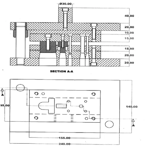
3.5 Assembled View of Progressive Tool
Fig. 3.3.Assembled View Of Progressive Tool
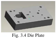
Fig. 3.4 Die Plate
Assuming that the die block (die plate) is considered to be as fixed beam. The shoe deflection is calculated using the strength of material formula for fixed supported beam,
Deflection, δ = FL3/192EI
Where,
F = 80% of cutting force = 0.8 x 25434 kgf = 203472 N
L = 125 mm, E = 2.1 x 10⁵ N/mm2 I =bh3/12= 3.48 x 105 mm4 Where, b = 155mm, h =30 mm
δ=(203472 x 1253)/(192 x2.1x105x 3.48 x 105.29 x 106)
=28.26µm
Stress, p = F/A
p = 203472 / (0.155 x0.085) = 5.98 x 10⁷N/m2
3.7 Bottom Plate Design
Fig. 3.5 Bottom Plate
Assuming that the bottom plate is considered to be on parallels. The shoe deflection is calculated using the strength of material formula for parallels supported beam,
Deflection, δ = FL3
/354EI Where,
F = 80% of cutting force = 0.8 × 254340 = 209419.3 N
E = 2.1 x 10⁵ N/mm2 I = bh3/12
= 1.8 x 106 mm4 Where, b = 286 mm, h =52 m δ = 11.03µm
Stress, p = F/A
p = 203472 / (0.240x 0.140) = 6.05 x 10⁶N/m2
3.8 Top Half Design
Fig. 3.6 Top Half
Top half includes as for calculation and analysis purpose as top plate, punch back plate and punch plate. Assuming that the Top plate is considered to be on parallels. The shoe deflection is calculated using the strength of material formula,
Deflection, δ = FL3/48EI
Where,
F = 80% of cutting force = 0.8×254340
= 203472 N L = 195 mm E = 2.1 x 10⁵ N/mm2 I = bh3/12
= 2.5 x 106 mm4
Where, b= 240 mm, h= 60 mm δ = 3.4 µm
Stress, p=F/A
= 203472/(0.24×0.14) =6.05 x 10⁶N/m2
3.9 Stripper Plate Design
Fig.3. 7 Stripper Plate
Assuming fixed stripper to be considered as a fixed beam support.The fixed stripper plate deflection and stress is calculated using strength of material formulae for parallels supported beam,
Deflection δ = FL3/192EI
L = 125 mm, E = 2.1 x 10⁵N/mm2
I = bh3/12 = 4.35x 104mm4 Where, b= 155 mm,h= 15 mm
δ = 11.92µm
Stress, p = F/A
p = 52354.8 / (176 x 20) = 1.93x 10⁶N/m2
3.10 Piercing Punches
Fig. 3.8 Piercing Punches
Assuming that the piercing punch as consider as one end is fixed and compressive force is acting on other end. Here for cutting operation (piercing operation) 80% of cutting force is acting on punch as compressive nature.
We know that the compressive force on the punch is equal to the shear force on sheet metal.
Piercing Punch-1
Deflection of piercing punch, δp = Pp L / Ap E
Where ,
PP = Compressive force for
piercing operation
= 37699.1 N L = 42 mm, Ap= 19.63mm
2 ,E = 2.1 x 10⁵ N/mm2
δp = 3.83 µm
Stress, p = F/A p = 2.89×10⁶
Piercing Punch-2
Deflection of piercing punch, δp = Pp L / Ap E
Where ,
PP = Compressive force for
piercing operation
= 30159.2 N L = 42 mm, Ap= 50.26bmm2
,E = 2.1 x 10⁵ N/mm2
δp = 1.19µm
Stress, p = F/A p = 3.50×10⁶
Square Piercing Punch
Deflection of piercing punch, δp = Pp L / Ap E
Where , PP = Compressive force for
piercing operation
= 27600 N L = 42 mm, Ap= 30mm
2 ,E = 2.1 x 10⁵ N/mm2
δp = 1.84 µm
Stress, p = F/A p = 2.63×10⁶
3.11 Blanking punch
Fig. 3.9 Blanking Punch
Assuming that the blanking punch as consider as one end is fixed and compressive force is acting on other end. Here for cutting operation (blanking operation) 80% of cutting force is acting on punch as compressive nature. Deflection of blanking punch,
δp = Pp L / Ap E
Where , Pb = Compressive force for
piercing operation
= 16849.2 N Ab = 2102.13 mm2
E = 2.1 x 10⁵ N/mm2 L = 42mm
Deflection of blanking punch, δb = 1.603 µm
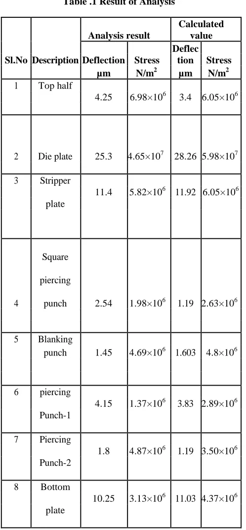
4. Result of Analysis
Table .1 Result of Analysis
5. Conclusion
progressive tool were modelled in Pro-Engineer 4.0. Each individual file was imported to Ansys12.0 software through Initial Graphics Exchange Specification (IGES) format. The following conclusions were made.
1. The results obtained through analysis are
approximately nearer to the theoretical values. This demonstrates that the analysis carried out was correct.
2. It is also observed that the design of progressive
tool is safe as all the stress values were less than the allowable stress of the material.
3. Manufacturing of progressive tool by analysis
result facilitates risk free manufacturing environment, which goes a long way to minimize the overall cost of production.
4. The analysed values reduce the uncertainties in
combinations which may induce heavy manufacturing losses by prematic die failure.
References
[1].Taylan Altan, Metal Forming Handbook, Schuler,
Berlin Heidelberg, 1998
[2].Ivana Suchy, Hand Book of Die Design, 2nd edition
McGraw-Hill, 2006, 1998.
[3]. Vukota Boljanovic, Ph.D. Sheet Metal Forming Process and Die Design, Industrial Press New York, 2004.
[4 David Alkire Smith, Die Materials and Treatments C18.docRev September1, 2005.
[5].Cyril Donaldson, George H LeCain, VC Goold, Tool
Design, 3rd edition,Tata McGraw- Hill.
[6].Ch.Mastanamma , K.Prasada Rao, Dr. M.Venkateswara Rao Design and Analysis of Progressive Tool (IJERT) Vol. 1 Issue 6, August, 2012.
[7].Prakash H. Joshi, Press Tools Design and Construction, A.H. Wheeler and Co. Ltd, 411,Surya Kiran, K.G.Marg, New Delhi.
David T. Reid, Fundamentals of Tool Design, 3rd
edition, Society of Manufacturing Engineers (SME).
Analysis result
Calculated value
Sl.No DescriptionDeflection Stress
Deflec tion Stress
µm N/m2 µm N/m2
1 Top half
4.25 6.98×10⁶ 3.4 6.05×10⁶
2 Die plate 25.3
4.65×10⁷ 28.26 5.98×10⁷
3 Stripper
11.4 5.82×10⁶ 11.92 6.05×10⁶
plate
4
Square
piercing
punch 2.54 1.98×10⁶ 1.19 2.63×10⁶
5 Blanking
punch 1.45 4.69×10⁶ 1.603 4.8×10⁶
6 piercing
4.15 1.37×10⁶ 3.83 2.89×10⁶
Punch-1
7 Piercing
1.8 4.87×10⁶ 1.19 3.50×10⁶
Punch-2
8 Bottom
10.25 3.13×10⁶ 11.03 4.37×10⁶