Command Manual
Copyright 1997
ADDENDUM-001 ADDENDUM-002 ADDENDUM-003 ADDENDUM-004
DATE AUGUST, 1998 DATE JANUARY, 1999 DATE DATE
ADDENDUM-005 ADDENDUM-006 ADDENDUM-007 ADDENDUM-008
DATE DATE DATE DATE
NEAX2000 IVS
2 3 4 5 6 7 8 9 10 11 12
13 2.1
14 15 16 17 18 19
20 2.2
21 22 23 24 25 26 27 28 29 30 31 32
40 41 42 43
44 2.1
44-1 2.1 44-2 2.1
45 2.2
46 47 48 49
50 2.1 2.2
51 52 53 54 55 56 57
58 2.1
59 60 61
62 2.2
63 64 65
66 2.1
67 2.1
ADDENDUM-001 ADDENDUM-002 ADDENDUM-003 ADDENDUM-004
DATE AUGUST, 1998 DATE JANUARY, 1999 DATE DATE
ADDENDUM-005 ADDENDUM-006 ADDENDUM-007 ADDENDUM-008
DATE DATE DATE DATE
NEAX2000 IVS
74 2.1
74-1 2.1 74-2 2.1
75 76
77 2.2
77-1 2.2
77-2 2.2
78 2.2
79 2.1
80 81 82
83 2.1
84 2.1
85 86 87
88 2.1
89
90 2.1
91 92 93 94 95
96 2.1
97 98 99 100
108 109
110 2.1 2.2
110-1 2.1 2.2 110-2 2.1
111 112 113 114 115 116 117 118 119 120
121 2.1
122 123 124 125
126 2.2
127
128 2.1
129 2.1
130 2.2
ADDENDUM-001 ADDENDUM-002 ADDENDUM-003 ADDENDUM-004
DATE AUGUST, 1998 DATE JANUARY, 1999 DATE DATE
ADDENDUM-005 ADDENDUM-006 ADDENDUM-007 ADDENDUM-008
DATE DATE DATE DATE
NEAX2000 IVS
142 143 144 145 146 147 148 149 150 151 152
153 2.1
154
155 2.1
156 2.2
156-1 2.2
156-2 2.2
157 158 159
160 2.1 2.2
161 162 163 164 165 166 167 168 169 170
176 177 178 179 180 181 182 183
184 2.2
185 186 187 188
188-1 2.1 188-2 2.1
189 190
191 2.1
192
193 2.1
194 195 196 197 198
199 2.1
199-1 2.1 199-2 2.1
200 2.1 2.2
ADDENDUM-001 ADDENDUM-002 ADDENDUM-003 ADDENDUM-004
DATE AUGUST, 1998 DATE JANUARY, 1999 DATE DATE
ADDENDUM-005 ADDENDUM-006 ADDENDUM-007 ADDENDUM-008
DATE DATE DATE DATE
NEAX2000 IVS
210 2.2
211 212
213 2.2
214
215 2.1
216 2.1 2.2
216-1 2.1 216-2 2.1
217 2.1
218 2.1
219 220
221 2.1
222 223 224 225 226 227 228 229 230 231 232
233 2.2
234 2.2
235
236 2.1
237 2.1 2.2
238
246
247 2.2
248 249 250 251 252 253 254 255 256 257 258 259 260 261 262
263 2.1
264 2.1
265
266 2.1
267 268 269 270 271 272 273 274 275
ADDENDUM-001 ADDENDUM-002 ADDENDUM-003 ADDENDUM-004
DATE AUGUST, 1998 DATE JANUARY, 1999 DATE DATE
ADDENDUM-005 ADDENDUM-006 ADDENDUM-007 ADDENDUM-008
DATE DATE DATE DATE
NEAX2000 IVS
284 285 286
287 2.1 2.2
288 2.1
289 2.1
290 2.1
291 292 293 294 295 296 297 298 299 300 301 302 303 304 305 306 307 308 309
310 2.2
311 2.2
311-1 2.2
311-2 2.2
312
320 321 322 323
324 2.1
325
326 2.1
327 2.1
327-1 2.1 327-2 2.1 2.2 327-3 2.1 327-4 2.1
ADDENDUM-001 ADDENDUM-002 ADDENDUM-003 ADDENDUM-004
DATE AUGUST, 1998 DATE JANUARY, 1999 DATE DATE
ADDENDUM-005 ADDENDUM-006 ADDENDUM-007 ADDENDUM-008
DATE DATE DATE DATE
NEAX2000 IVS
354 355 356 357 358 359 360 361 362 363 364 365 366 367 368 369
370 2.1
371 2.1
372 373 374 375 376 377 378 379 380 381 382 383 384
392 393 394
395 2.1
396 397
398 2.2
399 2.2
400 401 402 403 404 405 406 407 408 409 410 411
412 2.2
413
414 2.2
ADDENDUM-001 ADDENDUM-002 ADDENDUM-003 ADDENDUM-004
DATE AUGUST, 1998 DATE JANUARY, 1999 DATE DATE
ADDENDUM-005 ADDENDUM-006 ADDENDUM-007 ADDENDUM-008
DATE DATE DATE DATE
NEAX2000 IVS
Page
LIST OF FIGURES . . . v
LIST OF TABLES . . . vi
CHAPTER 1 INTRODUCTION . . . 1
1. PURPOSE . . . 1
2. OUTLINE OF THE MANUAL . . . 1
CHAPTER 2 INFORMATION FOR DATA PROGRAMMING . . . 3
1. GENERAL . . . 3
2. DESCRIPTION OF CAT AND MAT . . . . 3
2.1 How to Use the CAT. . . 3
2.1.1 CAT Key Functions . . . 3
2.1.2 CAT Mode Setting Procedure . . . 6
2.1.3 Notice on the CAT Mode . . . 6
2.2 CAT Operation . . . 7
2.3 Error Messages . . . 10
3. COMMAND REFERENCE TABLE. . . 11
3.1 List of Commands . . . 11
3.2 Quick Reference Table of Commands Required for Service Feature . . . 14
4. PRECAUTION . . . 55
4.1 Conditions for Using Commands . . . 55
4.2 Method of Setting On-Line/Off-Line Mode . . . 56
4.3 Method for Installing Line/Trunk Cards . . . 57
4.4 Password Entry . . . 59
CHAPTER 3 DESCRIPTION OF COMMANDS . . . 61
1. GENERAL . . . 61
2. DETAILED DESCRIPTION OF COMMANDS . . . 61
[CM00] System Data Memory All Clear . . . 62
[CM01] System Data Memory Partial Clear . . . 63
[CM02] Setting of System Clock. . . 64
[CM03] Log In/Log Out of Password Mode . . . 65
[CM04] Language Indicated on Multiline Terminal LCD . . . 66
[CM05] Card Assignment . . . 67
[CM06] Misc. Trunk Number Assignment. . . 69
[CM07] DTI Trunk/ISDN Trunk Assignment . . . 70
[CM08] Basic Service Features . . . 71
[CM09] Additional Service Features . . . 89
[CM10] Station Number, Trunk Number, Card Number . . . 90
[CM19] Secretary/Group Diversion Station Number. . . 124
[CM1A] Data Station Number . . . 125
[CM1B] ISDN Terminal Multipoints Station Number Assignment . . . 126
[CM1C] PS Station Number Assignment . . . 127
[CM1D] PS-ID Assignment/PS Operation Data Download . . . 128
[CM20] Numbering Plan . . . 129
[CM21] Single Digit Access Code. . . 142
[CM22] Route Advance . . . 143
[CM23] Tenant Development . . . 144
[CM24] Kind of Calling Terminal Development. . . 145
[CM25] Kind of Special Terminal Development . . . 146
[CM26] Closed Number Development . . . 147
[CM29] Numbering Plan Tenant Group . . . 149
[CM2A] ID Code Assignment with MP . . . 150
[CM30] Trunk Data . . . 152
[CM31] System Attribute Data . . . 158
[CM35] Trunk Route Data. . . 160
[CM36] Restriction Data for Tandem Connection . . . 175
[CM38] AMP Trunk . . . 176
[CM40] Function of RS-232C Interface Circuit . . . 178
[CM41] System Timer Data . . . 183
[CM42] System Counter Data/pad Data/trunk Restriction Class Conversion . . . 197
[CM44] External Equipment Starting Conditions . . . 203
[CM45] Purpose of PBR/CFT . . . 205
[CM48] Hold/wake-up/timed Reminder/automated Attendant Tone . . . 208
[CM49] Digital Announcement Trunk . . . 212
[CM50] Common Route Indial . . . 217
[CM51] Automatic Transfer Destinations . . . 219
[CM52] Hot Line . . . 222
[CM53] Trunk Answer From Any Station Restriction . . . 224
[CM56] Intercom Zone Paging Group/Intercom Group. . . 225
[CM58] LDN Diversion . . . 227
[CM59] TAS/ACD/UCD Relay Interruption Pattern. . . 230
[CM5A] Virtual Line – Virtual Trunk Path Setting . . . 231
[CM60] ATT Group, Functions . . . 232
[CM61] External Key Function . . . 234
[CM62] Tenants For Each Att Group . . . 235
[CM63] Restriction of Inter-Tenant Connection . . . 236
[CM64] Automated Attendant . . . 237
[CM65] Service Features on Tenant Basis. . . 238
[CM71] Memory Allocation for System Speed Dialing . . . 240
[CM72] Stored Number for System Speed Dialing . . . 243
[CM88] Automatic Pause Entry Table . . . 258
[CM8A] LCR/Toll Restriction Development Table . . . 259
[CM90] Multiline Terminal/SN610 ATTCON/Add-On Module Key Assignment . . . 267
[CM93] Prime Line . . . 301
[CM94] Multiline Terminal One-Touch Memory . . . 302
[CM96] DSS Console Number . . . 303
[CM97] DSS Console Key Assignment . . . 304
[CM98] Add-On Module Number . . . 308
[CM9A] Multiline Terminal Soft Key Assignment . . . 309
[CMA0] Type Of Data Adapter . . . 312
[CMA1] Data Terminal Attribute Data . . . 313
[CMA5] Nailed Down Connection . . . 316
[CMA6] Attribute Data For RS-232C Port On AP01 . . . 317
[CMA7] CCIS Channel Data . . . 320
[CMA8] CCIS Routing Label Assignment . . . 322
[CMA9] ISDN D-Channel Assignment . . . 323
[CMAA] DTI/DCH/CIR Card Functions . . . 324
[CMAC] ISDN Functions . . . 325
[CMAD] ZT Calling Area/Pad Data Assignment . . . 326
[CMAE] ZT Operation Data Assignment . . . 327
[CMAF] Visitor PS Data Assignment. . . 327-2 [CMB0] Peg Count . . . 328
[CMB1] Traffic Measurement . . . 332
[CMB3] UCD Peg Count . . . 334
[CMD5] ID Code Assignment With AP . . . 336
[CMD6] ID Code All Clear With AP . . . 338
[CMD7] OAI Control Data . . . 339
[CMD9] Centralized Billing Data Port Assignment . . . 342
[CMDB] Calling Number Development Data . . . 343
[CMDC] Calling Number Development Table . . . 346
[CME0] Initialization . . . 347
[CME5] Station, Trunk Line Make Busy . . . 348
[CME6] Call Forwarding Set/Reset From MAT/CAT . . . 349
[CME7] Password Level . . . 350
[CME9] Password Code . . . 351
[CMEA] Fault Information Store/Display Functions . . . 352
[CMEC] Battery Release/Line Status Display . . . 361
[CMEE] Virtual Tie Line Set/Release . . . 363
[CME1, F0, F1] Special Commands . . . 364
[CMF2, F3] Special Commands . . . 365
[CMF5] Special Commands . . . 366
[CMF8] Special Commands . . . 368
[CMD026] Route Index For Call Charge Development . . . 400
[CMD027] Call Charge Development Tables . . . 401
[CMD031] ROOM STATUS CODE . . . 402
[CMD033] Route Index For Call Development . . . 404
[CMD034] Call Development Tables. . . 405
[CMD035] Designation Of Printer . . . 407
[CMD100] System Data Partial Clear . . . 408
[CMD101] System Data All Clear . . . 409
[CMD102] Additional Memory Clear . . . 410
CHAPTER 4 RESIDENT SYSTEM PROGRAM . . . 411
1. GENERAL . . . 411
2. PROCEDURE FOR LOADING THE RESIDENT SYSTEM PROGRAM . . . 411
3. SERVICE CONDITIONS . . . 411
Table 2-7 List of Commands for Each Hotel/Motel Feature . . . 51
Table 2-8 Commands and Their Using Conditions . . . 55
Table 2-9 Port Assignment on Each Line/Trunk Card . . . 58
Table 2-10 Example of Password Level Assignment . . . 59
Table 3-1 Quick Reference Data Table for SMDR (NEAX2400 IMS Format) . . . 386
Table 3-2 Quick Reference Data Table for SMDR (NEAX1400 IMS Format) . . . 387
Table 3-3 Quick Reference Data Table for Printer . . . 388
Table 3-4 Quick Reference Data Table for PMS (IMS Format) . . . 389
Table 3-5 Quick Reference Data Table for VMS with MCI . . . 390
Table 4-1 Basic Service Feature . . . 412
Table 4-2 Station Number, Trunk Number, Card Number . . . 413
Table 4-3 Station Class Data: Initial Data . . . 414
Table 4-4 Numbering Plan . . . 415
Table 4-5 Trunk Data . . . 417
Table 4-6 Trunk Route Data . . . 419
Table 4-7 Memory Allocation for System Speed Dialing . . . 425
Table 4-8 Memory Allocation for Station Speed Dialing . . . 426
Table 4-9 Multiline Terminal Line Key Data . . . 427
Table 4-10 Prime Line . . . 428
2. OUTLINE OF THE MANUAL
This manual consists of the introduction (Chapter 1) and the following chapters:
•
CHAPTER 2 (INFORMATION FOR DATA PROGRAMMING):
This chapter provides the basics of Customer Administration Terminal (CAT) programming, a command
reference table and precautions for using commands.
•
CHAPTER 3 (DESCRIPTION OF COMMANDS):
This chapter provides a detailed description of each command.
•
CHAPTER 4 (RESIDENT SYSTEM PROGRAM):
2. DESCRIPTION OF CAT AND MAT
In the PBX, the CAT or MAT is used for programming.
The CAT is a digital multi-function telephone (Multiline Terminal) which is equipped with function keys, a
dial- pad and LCD (16 characters), and interfaces with the system via the MP card.
The MAT is the personal computer, which interfaces with the system via the MP card. For further details, refer
to the MAT Operation Guide.
2.1 How to Use the CAT
2.1.1 CAT Key Functions
Figure 2-1 CAT Key Assignment for ETJ-16DD-1
A B C D
E F & –
ST EXE CE S
, – ← DE
1 2 3 DE
4 5 6 –
7 8 9 EXE
A 0 B ST
← , CE S
G Q
H R
I S
J T
K U
L V
M W
N X
O Y
S Display of next data (Step forward)
, Separator; to be entered between two different data such as first/second data of CM72/74/ 90/97.
— Display of previous data (Step backward)
← Cancel of one character out of the entered data (Backspace)
DE Data End; to be entered at the end of the command code or at the end of each data entry.
Table 2-2 Digit Keys
DIGIT KEY MEANING
0-9, A-F Data (Data is entered by hexadecimal code 0 - F)
A *: As a dial digit
B #: As a dial digit
C Clear Assigned data by “CCC”
2.1.3
Notice on the CAT Mode
(1) CAT mode is used in on-line mode. Therefore, system data clear commands (CM00, CM01) cannot be
accessed from the CAT.
(2) To use the CAT after clearing all system data, perform the following operations on the system:
(a) Plug a PN-2DLCB/4DLCA card into the LT00 slot of PIM0.
(b) Connect the CAT (Multiline Terminal) to LEN0000 at the MDF.
(c) Set SW3 on the MP card to “B”.
(d) Depress SW1 on the MP card. (System Data All Clear)
(e) Set SW3 on the MP card to “0”, and depress SW1. (On-Line mode)
(f)
Set the CAT mode on the Multiline Terminal.
(3) During CAT mode, do not change or delete the following data:
•
CM10, My Line Number of the CAT.
(4) There are no limitations on the number of Multiline Terminals in the system that can be programmed to
allow CAT capability. However, the number of Multiline Terminals that can be placed into CAT mode, at
– CNF lamp flashes – CNF, SPKR, ANS lamp on
3. Press – “CAT MODE” displayed on LCD
– CNF lamp off 7. Press
4. Press – “COMMAND=–” displayed on LCD
Note:
Steps 1 through 6 need to be completed within 4 seconds.
To clear CAT mode:
While “COMMAND =– is displayed on the LCD.
1. Lift handset (Off Hook) - SPKR lamp off.
2. Replace handset (On Hook) - CNF, ANS lamps off. - LCD returns to clock.
*
•
Second Data
An explanation of the data entry procedure follows:
(a) Operation for confirming the existing office data
With the above entry completed, the present second data is displayed on the LCD.
If the second data is not assigned yet, either the initial data value or “NONE” is displayed.
(b) Operation for assigning (changing) the office data
With EXE pressed, "OK" is displayed on the LCD.
To confirm the data assigned, depress DE after entering the first data.
(c) Use of
button and
button
•
If
is pressed after setting the second data (after
has been pressed), the next first data
is displayed.
•
If
is pressed after setting the second data (after
has been pressed), the last data is
dis-played.
+ Command Code +
+ First Data +
ST
DE
DE
+ Command Code +
+ First Data +
+ Second Data +
+
ST
DE
DE
DE
EXE
S
–
S
EXE
Note 1:
When no data exists, “NONE” is displayed. And when data exists, that data is displayed.
Note 2:
This operation is for confirming the data assignment. Thus it may be omitted.
STEP 2 Press .STEP 3 Enter “10” (Command Number).
STEP 4 Press .
STEP 5 Enter “0000” (LEN).
STEP 6 Press . Note 1
STEP 7 Enter “300” (Station Number).
STEP 8 Press .
STEP 9 Press . Note 2
STEP 10 Press . Note 1
STEP 11 Enter “301” (Station Number).
STEP 12 Press .
STEP 13 Press . Note 2
STEP 14 Turn OFF power switch.
ST
COMMAND = _
COMMAND = 10 _
DE
10> _
10> 0000_
DE
10> 0000: NONE-_
10> 0000: NONE-300
EXE
OK _
DE
10> 0000: 300-_
S
10> 0001: NONE__
10> 0001: NONE-301
EXE
OK _
DE
10> 001 : 301 _
(3) Example of Deleting Station Number “300” assigned to LEN000
STEP 2 “0001” has been entered instead of “0000” as intended.
STEP 3 “0001” has been assigned as first data after pressing .
STEP 4 If is pressed, the state returns to that of Step 1.
STEP 5 Enter “0000”.
STEP 6 Press , and assign the correct first data.
• If, in Step 11 in Table 2-3, when “302” has been entered instead of “301”, press . Then the cursor moves to the position of “2”.
STEP 1 In Step 11, enter “302” instead of “301” as intended.
STEP 2 Press .
STEP 3 Press digit Key “1”.
0000 is to be deleted after completing all the operations in Table 2-3.
STEP 1 Press .
STEP 2 Enter “10” (Command Number).
STEP 3 Press .
STEP 4 Enter LEN “0000”.
STEP 5 Press .
STEP 6 Enter “CCC”.
STEP 7 Press .
STEP 8 Press .
10> 0001_
DE
10> 0001: NONE-__
CE
10> _
10> 0000_
DE
10> 0000: NONE__
←
10> 0001: NONE-302
←
10> 0001: NONE-30__
10> 0001: NONE-301__
ST
COMMAND = _
COMMAND = 10 _
DE
10> _
10> 0000
DE
10> 0000:
300-10> 0000: 300-CCC
EXE
OK
ERROR MESSAGE MEANING OF MESSAGE ACTION
DIGIT ERROR Error in the number of digits entered. Press “ST” or “CE” and enter correct data.
DATA ERROR The value of the entered data is incorrect. Same as above.
CODE NOT USED The command code entered is not in use, or password is needed.
Same as above, or follow the procedure for entering a password.
DATA NOT FOUND A Station Number not assigned has been en-tered.
Same as above.
WAIT BUSY NOW The station or trunk, for which data is to be changed, is busy.
Wait until it becomes idle.
ASSIGNED ALREADY This error message is displayed when not enough digits are entered. For example, when assigning “12” for a service access code, even if “123” has already been used for an-other service access code.
Press “ST” or “CE” and enter correct data.
HARDWARE ERROR Memory read/write disabled. Check switch setting of MP card or replace MP card with spare.
WRONG • The data stored in the memory is wrong.
• This message is displayed when too many digits are entered. For example, when as-signing “123” for a service access code when “12” has already been used for an-other service code.
Clear present data by entering “CCC”, or en-ter correct data.
SEE CMxx YYYY Double assigned error of the same Station Number or trunk.
Station Number intended is already assigned to First Data of CMxx Confirm.
USE CMxxxx The data is already assigned by another com-mand.
Command Number and YY Number already assigned are displayed. Confirm.
TRK NOT ASSIGNED The designated trunk is not assigned. Assign the trunk by CM10.
xx > xxx: ERROR The first data has been changed by “S” or “-” button, but the station corresponding to that first data is not assigned.
COMMAND REMARKS CODE FUNCTION 00 01 02 03 04 05 06 07 08 09
System Data Memory All Clear System Data Memory Partial Clear Setting of System Clock
Log in/Log out of Password Mode
Language Indicated on Multiline Terminal LCD Card Assignment
MISC Trunk Number Assignment DTI Trunk/ISDN Trunk Assignment Basic Service Features
Additional Service Features
10 11 12 13 15 16 17 18 19 1A 1B 1C 1D
Station Number, Trunk Number, and Card Number Virtual-Line Number
Station Class-1 Station Class-2
Service Restriction Class
Call Pickup Group/Group Diversion Group UCD Group
Station Hunting Group
Secretary/Group Diversion Station Number Data Station Number
ISDN Terminal Multipoints Station Number Assignment PS Station Number Assignment
PS-ID Assignment/PS Operation Data Download
20 21 22 23 24 25 26 Numbering Plan
Single Digit Access Code Route Advance
Tenant Development
Kind of Calling Terminal Development Kind of Special Terminal Development Closed Number Development
29 2A
Numbering Plan Tenant Group ID Code Assignment with MP
30 31 35 36 38 Trunk Data
System Attribute Data Trunk Route Data
42 44 45 48
System Counter Data/PAD Data/Trunk Restriction Class Conversion External Equipment Starting Condition
Purpose of PBR/CFT
Determination of Tone/Tone Source
49 Digital Announcement Trunk PN-2DATA
50 51 52 53
Common Route Indial
Automatic Transfer Destinations Hot Line
Trunk Answer from Any Station Restriction
56 Internal Zone Paging Group/Intercom Group
58 LDN Diversion
59 TAS/ACD/UCD Relay Interruption Pattern For PN-DK00
5A Virtual Line - Virtual Path Setting
60 ATTCON Tenant Group, Functions For ATTCON
61 External Key Function For PN-DK00
62 Tenants for Each ATTCON Group For ATTCON
63 Restriction of Inter-Tenant Connection
64 Automated Attendant
65 Service Features on Tenant Basis
71 72 73 74 76 77 78
Memory Allocation for System Speed Dialing Stored Number for System Speed Dialing Memory Allocation for Station Speed Dialing Stored Number for Station Speed Dialing Digit Conversion on DID Call
Station/Trunk Name Assignment Destination of Split Call Forwarding
81 85 88 8A
Toll Restriction Pattern on Each Trunk Restriction Class Maximum Digits on C.O. Calls
Automatic Pause Entry Table
94 96 97 98 9A
Multiline Terminal One-Touch Memory DSS Console Number
DSS Console Key Assignment Add-On Module Number
Multiline Terminal Soft Key Assignment
A0 A1 A5
Type of Data Adapter Data Terminal Attribute Data Nailed Down Connection
A6 Attribute Data for RS-232C Port on AP01 For PN-AP01
A7 A8 A9 AA AC AD AE AF
CCIS Channel Data
CCIS Routing Label Assignment ISDN D-Channel Assignment DTI/DCH/CIR Card Functions ISDN Functions
ZT Calling Area/PAD Data Assignment ZT Operation Data Assignment Visitor PS Data Assignment
B0 B1 B3
PEG Count
Traffic Measurement UCD PEG Count
Used for maintenance
D5 ID Code Assignment with AP
D6 ID Code All Clear with AP For PN-AP01
D7 D9 DB DC
OAI Control Data
Centralized Billing Data Port Assignment Calling Number Development Data Calling Number Development Table
E0 E5 E6 E7 E8 E9 EA EC EE Initialization
Station Trunk Make Busy
Call Forwarding Set/Reset from MAT/CAT Password Level
Manual Path Connection Password Code
Fault Information Store/Display Functions Battery Release/Line Status Indication Virtual Tie Line Set/Release
Used for maintenance
F0 F1 F2 F3 F5 F8
MP Memory Dump MP Memory Read/Write FP Memory Dump FP Memory Read/Write
Line/Trunk Memory/Alarm Memory Read ID Code for Key FD
(F/S)
CODE Y-YYY
Account Code 08 – 362/S
12 02 F/S
15 30 F/1
20 0 – 3 F/085
42 – 10/S
90 00 F/F0085
Add-On Module 10 – F/S
12 05 F/0
30 18 F/0
41 1 09/S
90 00 – 03 F/S
98 0 F/S
Alarm Indications – – –
Alphanumeric Display 08 – 255/1
20 0 – 3 F/A10
35 03 F/S
77 0 – 3 F/S
Analog Port Adapter 10 – F/S
13 09,
32 – 35
F/S
90 00 F/S
Announcement Service 08 – 124/S
10 – F/S
12 02 F/S
15 34 – 39 F/1
20 0 – 3 F/A00 – A09
30 03, 05 F/S
35 69 – 73 F/1
41 0 45, 53/S
48 0 F/0500
49 00, 05 – 07
F/S
65 50, 51 F/0
Answer Key 12 02 F/S
15 72 F/0
Attendant-Assisted Calling 08 – 018, 048, 142, 143/S
20 0 - 3 F/800
60 00, 01 F/S
62 0 - 3 F/0
Attendant Camp-On 08 – 068, 441/S
20 0 - 3 F/021
41 0 00/S
Attendant Console (SN610 ATTCON)
10 – F/S
30 02, 03 F/14
60 00, 01, 07, 17
F/S
62 0 - 3 F/S
Attendant Console (SN716 DESK CON)
10 – F/S
30 02, 03 F/14
60 00, 01, 15 F/S
62 0 - 3 F/S
90 00 F/S
• Attendant Calling/Called Name Display
08 – 255/1
20 0 - 3 F/A10
35 03 F/S
77 0 - 3 F/S
• Attendant Called/Calling Number – – –
• Attendant Call Selection 35 15 F/S
90 00 F/S
• Attendant Console Lockout Password
08 – 353/S
20 0 - 3 F/A55
60 30 0/S
90 00 F/F6110
• Attendant Do Not Disturb Setup and Cancel
13 00 F/0
90 00 F/S
• Attendant Interposition Calling/ Transfer
08 – 143/S
20 0 - 3 F/095
90 00 F/F6067
• Attendant Lamp Check – – –
• Attendant Listed Directory Number
08 – 204, 205/0
35 15 F/S
50 01, 02 F/S
58 00 - 09 F/S
• Attendant Loop Release 08 – 014/0
20 0 - 3 F/021
• Attendant Programming 08 – 229/S
20 0 - 3 F/A56
60 30 1/S
90 00 F/611
• Attendant Training Jack – – –
• Audible Indication Control – – –
• Call Processing Indication – – –
• Call Queuing 42 – 00/S
• Call Splitting 90 00 F/S
• Call Waiting Display 42 – 00/S
• Common Route Indial 08 – 204, 205/0
50 01 F/S
58 00 – 09 F/S
90 00 F/S
• Dialed Number Identification Service
08 – 204, 205/0
35 15 F/S
50 01, 02 F/S
58 02, 03, 08, 09, 10
F/S
90 00 F/S
• Incoming Call Identification – – –
• Individual Trunk Access 20 0 – 3 F/081
30 19 F/S
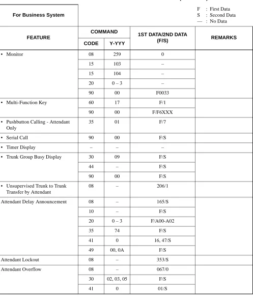
• Monitor 08 259 0
15 103 –
15 104 –
20 0 – 3 –
90 00 F0033
• Multi-Function Key 60 17 F/1
90 00 F/F6XXX
• Pushbutton Calling - Attendant Only
35 01 F/7
• Serial Call 90 00 F/S
• Timer Display – – –
• Trunk Group Busy Display 30 09 F/S
44 – F/S
90 00 F/S
• Unsupervised Trunk to Trunk Transfer by Attendant
08 – 206/1
Attendant Delay Announcement 08 – 165/S
10 – F/S
20 0 – 3 F/A00-A02
35 74 F/S
41 0 16, 47/S
49 00, 0A F/S
Attendant Lockout 08 – 353/S
Attendant Overflow 08 – 067/0
30 02, 03, 05 F/S
(F/S)
CODE Y-YYY
Attendant Override 08 – 012, 045, 076/S
12 02 F/S
15 09 F/1
20 0 – 3 F/081
30 19 F/S
90 00 F/F6107
Authorization Code 05 – F/07
08 – 216, 362/S
12 02 F/S
15 31 F/S
20 0 – 3 F/086
42 – 11/S
D5 0, 1, 3 F/S
2A 0 – 4 F/S
Automated Attendant 08 – 180, 359, 363/S
10 – F/S
20 0 – 3 F/A00 – A02
30 02, 03, 30–33, 37
F/S
41 0 34, 39, 43, 59/S
45 2 F/0
48 2 06/S
49 00 – 02 F/S
63 2 F/S
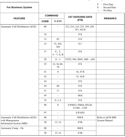
Automatic Call Distribution (ACD) 08 – 212, 214, 215, 227, 259, 265, 357, 442/S
10 F/S
12 02 F/S
15 33, 103, 104
F/1
17 0 – 2, 4 – 7, A, B
F/S
20 0 – 3 F/033, 044, 0045, A00 – A02
35 12, 18, 60, 78
F/S
41 0 16, 47/S
42 – 15, 16/S
44 – F/S
49 00 F/S
51 17 F/S
59 – 00/S
76 0, 1, 6 F/S
90 0 F/F0033, F0044, F0120, F1280 – 1295
97 – F/F1055
Automatic Call Distribution (ACD) with Management
Information System (MIS)
08 – 068/S Refer to ACD-MIS
System Manual
30 13, 14 F/06
Automatic Camp – On 08 – 068/S
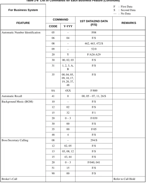
Automatic Number Identification 05 – F08
06 04 F/S
08 – 462, 463, 472/S
09 – 52/0
20 Y F/A26-A29
30 00, 02, 03 F/S
31 1, 2, 3, A, B
F/S
35 00, 04, 05, 09, 10, 17, 19, 20, 37,
48
F/S
8A 4XX F/800
Automatic Recall 41 0 00, 05 – 07, 11, 26/S
Background Music (BGM) 10 – F/S
12 02 F/S
15 32 F/1
20 0 – 3 F/039
30 00 F/S
35 00 F/05
48 4 F/S
Boss/Secretary Calling 08 – 294/S
12 02, 05 F/S
13 03, 08, 12 F/S
15 43, 44 F/S
20 0 – 3 F/040, 041
51 15 F/S
90 00 F/S
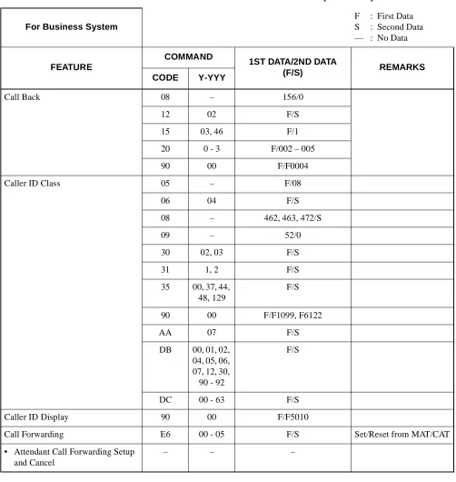
Call Back 08 – 156/0
12 02 F/S
15 03, 46 F/1
20 0 - 3 F/002 – 005
90 00 F/F0004
Caller ID Class 05 – F/08
06 04 F/S
08 – 462, 463, 472/S
09 – 52/0
30 02, 03 F/S
31 1, 2 F/S
35 00, 37, 44, 48, 129
F/S
90 00 F/F1099, F6122
AA 07 F/S
DB 00, 01, 02, 04, 05, 06, 07, 12, 30, 90 - 92
F/S
DC 00 - 63 F/S
Caller ID Display 90 00 F/F5010
Call Forwarding E6 00 - 05 F/S Set/Reset from MAT/CAT
• Attendant Call Forwarding Setup and Cancel
• Call Forwarding - All Calls 08 – 222, 386, 387/S
09 – 33/S
12 02 F/S
15 00, 26 F/1
20 0 - 3 F/010, 011
35 05 F/1
36 – F/0
48 2 13/S
65 23 - 25 F/1
90 00 F/F0010
E6 00 F/S
• Call Forwarding - Busy Line 08 – 222, 240, 386, 387/S
12 02 F/S
15 11, 12, 28, 29
F/1
20 0 – 3 F/012, 013, 014, 015
35 05 F/1
36 – F/0
65 23 – 25 F/1
• Call Forwarding - No Answer 08 – 222, 386, 387/S
12 02 F/S
15 10, 12, 27, 29
F/1
20 0 – 3 F/012, 013, 016, 017
35 05 F/1
36 – F/0
41 0 01, 15/S
65 23 – 25 F/1
90 00 F/F0012, F0016
• Call Forwarding - Destination 12 02 F/S
15 15 F/1
20 0 – 3 F/018, 019
90 00 F/F0018, F0019
• Multiple Call Forwarding -All Calls
42 – 14/S
• Multiple Call Forwarding -Busy Line
42 – 14/S
• Multiple Call Forwarding -No Answer
• Split Call Forwarding - All Calls 08 – 222, 386, 387/S
12 02 F/S
15 00, 26 F/1
20 0 – 3 F/010, 011, A80, A81
35 05 F/1
36 – F/0
48 2 13/S
65 23 – 25 F/S
78 – F/S
90 00 F/F0010, F0A80
• Split Call Forwarding - Busy Line 08 – 222, 240, 386, 387/S
12 02 F/S
15 11, 12, 28, 29
F/1
20 0 – 3 F/012 - 015, A82, A83
35 05 F/1
36 – F/0
65 23 – 25 F/S
78 – F/S
• Split Call Forwarding -No Answer
08 – 222, 386, 387/S
12 02 F/S
15 10, 12, 27, 29
F/1
20 0 – 3 F/012, 013, 016, 017, A82, A83
35 05 F/1
36 – F/0
41 0 01, 15/S
65 23 – 25 F/S
78 – F/S
90 00 F/F0012, F0016, F0A82
• Call Forwarding - Override – – –
• Group Diversion 08 – 026/0
16 2 F/S
19 6 F/S
41 0 01/S
Call Park – – –
• Call Park - System 08 – 133/S
12 07 F/S
15 96 F/S
20 0 – 3 F/008, 009
41 0 05/S
90 00 F/F5000, F6144
• Call Park - Tenant 08 – 133/S
20 0 – 3 F/062
41 0 05/S
Call Pickup – – –
• Call Pickup - Direct 12 02 F/S
15 14 F/1
20 0 - 3 F/021
90 00 F/F0021
• Call Pickup - Group 16 0 F/S
20 0 - 3 F/020
90 00 F/F0020
• Call Pickup - Designated Group 12 02 F/S
15 14 F/1
16 0 F/S
20 0 - 3 F/037
Call Redirect 51 18, 22 F/S
90 00 F/F5011/F5012
Call Transfer – – –
• Call Transfer - All Calls 08 – 068, 155, 319/S
• Call Transfer - Attendant 08 – 063, 142/S
20 0 - 3 F/800
62 0 - 3 F/0
Camp-On 08 – 050, 051, 068, 069,
146 – 148, 208, 322/S
12 02 F/S
15 16, 43, 44 F/1
20 0 - 3 F/007, A25
41 0 26/S
CCSA Access 20 0 - 3 F/100 – 163
35 00, 15 F/S
Centrex Compatibility 20 0 – 3 F/A58
35 16, 86 F/S
93 – F/S
Class of Service 12 00 – 03,
07
F/S
15 80,
82 – 84, 88 – 91, 96 – 98
F/S
35 51 – 58, 61 – 68
F/S
Code Restriction 08 – 035, 044, 119/S
12 01 F/S
35 11,
51 – 55, 76
F/S
81 01 – 13 F/S
85 0 – 4 F/S
8A 400–404, 100–115, 000–063, 500–755, 200–207, 300–303
F/S
Conference 08 – 101 – 104, 246/S
Consecutive Speed Dialing 05 – F/19
08 – 035, 168, 171, 252/S
12 02 F/S
15 07 F/1
20 0 – 3 F/064 – 066
73 – F/S
74 – F/S
90 00 F/S
94 – F/S
CMD000 – 56/1
Consultation Hold 08 – 137/0
12 07 F/S
15 88 – 91 F/1
Customer Administration Terminal (CAT)
12 02 F/S
15 56 F/1
E7 00 – 06, 10 – 16
F/S
E9 – 0 – 9/S
Data Line Security 13 07 F/0
Delayed Ringing 41 1 09/S
90 03 F/0
Diagnostics Refer to Maintenance
Dial Conversion 08 – 050, 051/0
10 – F/S
12 00 F/3
35 01,
23 – 26, 45, 46
F/S
45 0, 1 F/1
Direct Digital Interface (DDI) Refer to DDI System
Manual.
Direct Inward Dialing (DID) 08 – 180/S
10 – F/S
30 00 – 05 F/S
35 00, 02, 05, 12, 18
F/S
41 0 01, 45/S
45 1 F/S
49 00 F/S
51 00, 03, 06 F/S
Direct Inward System Access (DISA)
05 – F/07
08 – 180, 217, 352/S
10 – F/EBXXX
15 33 F/S
20 0 – 3 F/A00, A01
2A 5 – 8 F/S
30 02, 03, 30, 31
F/S
35 18 F/0
41 0 39/S
42 – 13/S
76 0, 1 F/D16
D5 0, 1, 3 F/S
Direct Inward Terminator (DIT) 08 – 179/S
30 02, 04, 13, 15
F/S
41 0 01/S
Direct Outward Dialing (DOD) 10 – F/S
20 0 – 3 F/100 – 163
30 00, 01, 08 F/S
35 00 – 02, 04, 05, 08,
09, 20 – 26, 45, 46
F/S
41 0 27/S
Direct Station Selection/Busy Lamp Field (DSS/BLF) Console
08 – 269/274/S
10 – F/S
96 – F/S
97 – F/S
Distinctive Ringing 08 – 137, 138, 179, 180/S
35 32, 33 F/S
Do Not Disturb 08 – 240, 241/S
12 02 F/1
13 00 F/0
15 19 F/1
20 0 - 3 F/022, 023
48 2 14/S
51 10 F/S
90 00 F/S
Dual Hold 12 02 F/S
15 64 F/1
E & M Tie Line Access 10 – F/S
35 00 - 02, 04, 05, 08 - 10,
13, 19, 20, 21, 23 - 26,
33, 34, 45, 46, 104, 105
F/S
42 – 50 - 65/S
45 1 F/0
49 00 F/0000, 0E00
51 01, 04, 07 F/EBXXX
Elapsed Call Timer – – –
Enhanced 911 05 – F/08
06 04 F/S
08 – 474, 475/S
09 – 52/0
12 12, 13 F/S
13 25 F/S
20 0 - 3 F/A26-A28
31 2 0 - 3/0
35 03, 04, 14, 20, 36, 38, 76, 129
F/S
50 05 F/S
85 0 - 7 F/S
8A YYY F/S
AA 07 F/3
Executive Calling 13 21 F/0
Executive Override 08 – 045, 115/S
12 02 F/S
15 05, 09 F/1
20 0 - 3 F/006
45 6 F/1
External Paging with Meet-Me 08 – 094, 096, 149, 157, 445/S
10 – F/S
12 02 F/S
15 08 F/1
20 0 - 3 F/100 - 163, 070 - 079, 080
30 00, 28 F/S
35 00, 08 F/S
44 – F/S
90 00 F/6150 - F6159
Feature Activation from Secondary Extension
– – –
FAX Arrival Indicator 12 03, 05 F/00 - 03
13 29 F/0
51 14 00 - 03/S
52 00 - 99 F/S
90 00 F/S
Flexible Line Key Assignment 08 252 F/S
12 02 F/S
15 07 F/S
73 – F/S
90 00 F11XX
94 – F/S
Flexible Numbering Plan 08 050, 051, 069, 148, 156, 208
F/S
10 – F/S
20 – F/801 - 804
Flexible Ringing Assignment 08 – 390/1
12 02, 07 F/S
15 68, 83, 84 F/S
35 34 F/S
90 01 F/0
Forced Account Code 05 01 F/07
08 – 216, 362/S
12 02 F/S
15 31 F/1
20 0 - 3 F/087
42 – 11, 12/S
2A 0 - 4 F/S
D5 0, 1, 3 F/S
D6 0 0000/CCC
Group Listening 12 02 F/S
15 70 F/0
Handsfree Answerback – – –
Handsfree Dialing and Monitoring
– – –
Hold – – –
• Call Hold 12 02 F/S
15 01 F/1
20 0 - 3 F/046
90 00 F/F0046
• Exclusive Hold 08 – 130/1
41 0 06/S
Hotline 08 – 057/S
11 – F/S
12 03 F/04
52 00 - 99 F/S
71 – 65/S
72 – F/S
90 00 F/S
Individual Attendant Access 06 01 F/S
08 – 143/S
10 – F/E000 - E007
20 0 - 3 F/095
Intercept Announcement 10 – F/EB000 - EB127
12 02 F/S
15 33 F/1
20 0 - 3 F/A00 - 02
49 00 F0A00
51 07 F/S
Intercom – – –
• Manual Intercom 08 – 238/S
11 – F/A200 - A724
12 02, 03 F/S
15 09 F/0
56 11 F/S
• Automatic Intercom 08 – 237/S
11 – F/A000 - A131
12 03 F/05
13 11 F/S
56 10 F/S
90 00 F/A000 - A131
• Dial Intercom 08 – 239/S
11 – F/B000 - B924
12 02, 03 F/S
15 09 F/0
56 12 F/S
90 00 F/B000 - B924
Internal Tone/Voice Signaling 08 – 050, 051, 069, 148, 156, 270/S
12 02, 07 F/S
15 67, 99 F/S
20 0 - 3 F/A63
Internal Zone Paging with Meet-Me
08 – 158/S
12 02 F/S
15 49 F/1
20 0 - 3 F/A30 - A45, A64
56 00 - 07 F/S
90 00 F/F1270 - F1277
Last Number Redial 08 – 177, 178/S
20 0 - 3 F/069
Least Cost Routing 3/6 Digit 20 0 - 3 F/A26 - A28
35 11,
51 - 55
F/S
81 – F/S
85 01 - 13 F/S
8A 5-7, A00 100 - 115 200 - 207 300 - 303 405 - 407,
410 000 - 063 500 - 755 900 - 949 800 - 849
F/S
Line Lockout 08 – 153, 274/S
13 04 F/1
41 0 22/S
42 – 01/S
Line Preselection 08 – 199/S
Maintenance Administration Terminal (MAT)
03 – F/S
E7 00 - 06, 10 - 16
F/S
E9 – 0 - 9/S
• Configuration Report – – –
• Maintenance Printout – – –
• Peg Count B0 0, 2 F/S
B3 0 - 5 F/S
• Remove and Restore Service E5 0, 1 F/S
Message Center Interface (MCI) Refer to Message Center
Message Reminder 08 – 050, 051, 069, 148, 156, 208, 234 - 236,
280 - 294/S
12 02 F/S
13 03 F/0
15 47, 48 F/1
20 0 - 3 F/A46 - A49
51 15 F/S
90 00 F/F1005
Miscellaneous Trunk Access – – –
• Code Calling Equipment Access
10 – F/S
20 0 - 3 F/100 - 163
30 00, 01 F/S
35 00, 01, 08 F/S
44 – F/S
• Dictation Equipment Access 10 – F/S
20 0 - 3 F/100 - 163
30 00, 01 F/S
35 00, 01, 08 F/S
• Foreign Exchange (FX) Access 35 00 F/01
• Radio Paging Equipment Access 08 – 094, 095, 149, 157, 162/S
10 – F/S
12 02 F/S
15 08 F/1
20 0 - 3 F/100 - 163, 070 - 079
30 00, 28 F/S
35 00, 08, 13 F/S
• Wide Area Telephone Service (WATS) Access
35 00 F/02
Multiline Terminal Attendant Position
08 – 206, 244, 245, 250/S
10 – F/S
11 – F/S
12 02, 03 F/S
15 60, 71, 73 F/S
17 1, 2 F/S
20 0 - 3 F/088
30 02, 04 F/S
51 12 F/S
90 00 F/S
96 – F/S
97 – F/S
Music On Hold 08 – 183, 388/S
10 – F/S
12 02 F/S
15 33 F/1
20 0 - 3 F/A00 - A02
44 – F/0000 - 0009
48 0 F/S
49 00, 05 F/S
64 1 F/00 - 09
Night Service – – –
• Attendant Night Transfer 08 – 018/S
51 13 F/S
• Call Rerouting – – – See Night Connection
• Day/Night Mode Change by Attendant Console
20 0 – 3 F/A55
60 30 1/S
90 00 F/F6110
• Day/Night Mode Change by Station Dialing
08 – 244, 245/0
12 02 F/S
15 60 F/1
20 0 – 3 F/043
90 00 F/F0043
• Night Connection - Fixed 30 03, 05, 14, 16
F/S
41 0 01/S
• Night Connection - Flexible – – – See Night Connection
Fixed and Call Forward-ing - All Calls.
• Trunk Answer Any Station (TAS) 10 – F/E800 – E831
12 01, 02 F/S
15 53 F/1
20 0 – 3 F/047 – 051
30 03, 17 F/S
44 – F/S
53 0 – 4 F/S
59 – F/S
63 0 F/S
Off-Hook Alarm 12 07 F/S
13 02 F/0
15 97, 98 F/S
41 0 22/S
51 12 F/S
Off-Premises Extension 13 09 F/0
Pad Lock 05 – F/07
08 – 216, 281, 362/S
12 02 F/S
15 31, 75 F/S
20 0 – 3 F/029, 086
2A 0, 1, 3 F/S
42 – 11/S
D5 0, 1, 3 F/S
D000 – 150/1
D015 – F/S
D016 – xx06/1
D031 – F/S
Periodic Time Indication Tone 08 – 135, 136/S
12 02 F/S
13 07 F/1
15 61 F/1
41 0 09/S
Pooled Line Access 30 00 – 03 F/S
90 00 F/F411 – F4163
Power Failure Transfer 10 – F/S
Priority Call 08 – 250, 251/S
12 02 F/S
15 17, 18 F/1
20 0 – 3 F/088, 089
51 12 F/S
CODE Y-YYY
Privacy/Privacy Release 12 02 F/S
15 63 F/1
Private Line 12 16 F/S
35 98 F/S
42 – 08/S
Proprietary Multiline Terminal – – –
• Automatic Idle Return 08 – 172/1
• Called Station Status Display – – –
• Calling Name and Number Display
08 – 335
• Dynamic Dial Pad 12 02 F/S
15 120 F/0
93 – F/S
• Handsfree Unit – – –
• I-Hold/I-Use Indication – – –
• Microphone Control – – –
• Multiple Line Operation 90 01 F/S
• Mute Key 90 00 F/F5013
• Off-Hook Voice Announcement 08 – 270, 279/1
11 – F/CX – CXXXX
12 02, 07 F/S
13 28 F/S
15 67, 72, 99 F/S
20 0 – 3 F/A63
90 00 F/CX – CXXXX
CODE Y-YYY
• Recall Key 35 16, 86 F/1
41 2 17/S
90 00 F/F1009
• Relay Control Function Key 10 – F/E8XX
44 – F/1500
• Ring Frequency Control 08 – 262, 390/S
12 07 F/S
15 83, 84 F/S
35 34 F/S
• Soft Key 12 12, 23
90 00 F/F1091
9A 00-03, 10-13
F/S
• Volume Control – – –
Remote Hold 12 02 F/S
15 124 F/S
41 0 06/S
90 00 F/F1010
Remote Maintenance – – –
Reserve Power – – –
Resident System Program – – – See Chapter 4.
Return Message Schedule Display 08 – 334
12 02 F/S
15 19 F/1
20 0 – 3 F/A54, 023
Ringing Line Pickup 12 07 F/S
15 82, 86 F/0
Route Advance 20 0 – 3 F/200 – 231
22 00 – 31 F/S
Save and Repeat 90 00 F/F1001, F1013, F1014
Security Alarm 12 03 F/04
52 00 – 99 F/S
Six-/Ten-Party Conference 10 – F/ED00 – ED03
12 02, 05 F/S
15 69 F/1
20 0 – 3 F/A59 – A62
Software Line Appearance 11 – F/S
12 01 – 14 F/S
13 12, 13 F/1
90 00 F/S
Stack Dial 08 – 178/S
12 07 F/S
15 96 F/S
90 00 F/F1000, F6121
Station Hunting – – –
• Station Hunting - Circular 08 – 240/S
18 0, 1 F/S
• Station Hunting - Terminal 08 – 240/S
18 0, 1 F/S
• Station Hunting - Secretarial 08 – 240/S
18 2 F/S
19 0, 1, 2 F/S
Station Message Detail Recording Refer to SMDR System
Manual.
Station Speed Dialing 05 – F/19
08 – 035, 168, 171, 252/S
12 02 F/S
15 07 F/1
20 0 - 3 F/064 - 066
73 – F/S
74 – F/S
90 00 F/S
94 – F/S
Step Call 08 – 069, 163/1, 208/0
Supervisory Control of Peripheral Equipment
13 22 F/0
41 1 08/S
System Speed Dialing 08 – 043, 044, 110 - 112, 176/S
12 02 F/S
15 06 F/1
20 0 - 3 F/067, 068, A50 - A52
41 0 38/S
71 – 00 - 64/S
72 – F/S
74 – F/S
Tenant Service 12 04 F/S
20 0 - 3 F/S
23 00 - 23 F/S
29 – F/S
30 01 F/S
49 01 - 07 F/S
51 00 - 12/15 F/S
61 00 F/S
62 0 - 3 F/S
63 0 - 2 F/S
64 0 F/S
65 50/51 F/S
71 – F/S
8A 100 F/S
Tie Line Tandem Switching 36 – F/S
Timed Queue 41 0 35 – 37/S
Timed Reminder 08 – 228/S
10 – F/DB00, E8XX, EBXXX
12 02 F/S
15 13 F/1
20 0 - 3 F/024, 025, A00 – A02
41 0 23, 52/S
42 – 03, 04/S
44 – F/0100
48 1 00/0200, 0500, 1400
49 00, 08 F/S
90 00 F/F0024
Trunk-Direct Appearances 08 – 365/S
30 02, 18 F/S
90 00 F/D000 – D255/F0058
Trunk Queuing - Outgoing 08 – 196/S
12 02 F/S
15 02 F/1
20 0 – 3 F/000, 001, 004, 005
35 28 F/S
90 00 F/F0004
Trunk-to-Trunk Connection 08 – 028, 029/S
10 – F/C100-C163
12 07 F/S
15 90, 91 F/1
35 119 F/S
36 – F/S
38 00–07 F/S
Uniform Call Distribution (UCD) with Overflow
08 – 212, 214, 215, 227, 259, 357, 442/S
10 – F/S
12 02 F/S
15 33, 103, 104
F/1
17 0 – 2, 4 – 7, A, B
F/S
20 0 – 3 F/033, 044, 045, A00 – A02
35 18, 60 F/S
41 0 16, 47/S
42 – 15, 16/S
44 – F/S
49 00 F/S
51 17 F/S
59 – 00/S
76 6 F/S
90 00 F/F0033, F0044, F1020, F1280 – 1295
Uniform Numbering – Voice & Data 20 0 - 3 F/A26 - A29
35 17 F/S
50 00 0/S
80 – 0/2
8A A00,
405 - 407, 000 - 063, 500 - 755
F/S
CODE Y-YYY
Voice Guide 15 116 F/S
41 0 95/S
48 2 12, 13, 14/S
49 00, 13 F/S
Voice Mail Integration 08 – 063, 156, 208, 333, 428/S
12 02 F/S
13 03, 10, 13 F/S
15 24, 40 F/1
20 0 – 3 F/040, 041, A46, A47
41 0 00, 14, 44, 48, 49/S
50 00 3, 4/S
51 15, 18 F/S
77 0, 1 F/S
90 00 F/F1005, F5001, F6112, F6113, F6123
Whisper Page 08 – 268, 269/S
12 02 F/S
15 111, 112 F/S
20 0 – 3 F/A88
48 2 17/S
90 00 F/F0A88
Wireless Communication System (WCS)
– – – Refer to WCS System
(F/S)
CODE Y-YYY
Automatic Wake-Up 08 – 228, 282 – 284, 286,
287/S
10 – F/S
12 02 F/S
15 13, 20, 21, 33
F/1
20 0 – 3 F/024, 025, 027, 028, A00 – A02
41 0 23, 52/S
42 – 03, 04/S
44 – F/0100
48 1 00/XX00
49 00, 08 F/S
90 – F/S
Check In/Check Out D000 – 11/1
D001 – 12, 13/S
D015 – F/S
D016 – XX06/1
D031 – F/S
Direct Data Entry 20 0 – 3 F/097
90 00 F/F0097
D001 – 252, 253/S
D015 – F/S
Do Not Disturb 08 – 240,241/S
12 02 F/S
15 19 F/1
20 0 – 3 F/022, 023
48 2 14/S
51 10 F/S
90 00 F/S
Do Not Disturb - System 08 – 240, 241/S
13 00 F/0
48 2 14/S
51 10 F/S
90 00 F/S
Hotel/Motel Attendant Console 90 00 F/S
Hotel/Motel Front Desk Instrument
02 – 0, 1, 2/S
10 – F/S
12 02 F/S
15 62 F/1
90 00 F/S
D000 – 2/1
D001 – F/S
D035 – F/S
House Phone 08 – 055, 056/S
12 03 F/00 – 03
Maid Status 08 – 281/S
20 0 – 3 F/029
90 00 F/F1069
D015 – F/S
D016 – XX06/1
D031 – F/S
Message Registration – – – Refer to SMDR System
Manual
Message Waiting 08 – 233 – 235/S
12 02 F/S
13 03, 13 F/S
15 24, 40 F/S
20 0 – 3 F/040, 041, A47
48 2 12/S
51 15 F/S
90 00 F/S
Property Management System Interface
Refer to PMS System Manual.
Room Cut Off 08 – 232/S
51 11 F/S
90 00 F/S
D001 – 5, 13/S
D015 – F/S
D016 – XX06, XX46/1
D031 – F/S
D033 – F/S
D034 – F/S
Single Digit Dialing 20 0 – 3 F/808 – 811
21 0 – 3 F/S
Table 2-8 Commands and Their Using Conditions
CONDITION COMMAND REMARKS
Commands that require a reset of MP card after data setting
• System reset is made by pressing SW1 on MP card.
CM05: Card Assignment
CM06: MISC Trunk Number Assignment CM07: DTI Trunk Assignment
CM08 – 390, 391: Basic Service Feature CM09: Additional Service Features
CM10: Station Number/Trunk Number, and Card Number (System initialization is required only for assigning the PN-8RST, PN-CFT, ISDN Circuit).
CM1A: Data Station Number
CM60: YY = 00, 01, 02, 04, 06: ATTCON Tenant Group, Functions
CM62: Tenants for each ATTCON Group CMA9: ISDN-channel Assignment CAF8: ID Code for Key FD
Commands that require a reset of AP card (PN-AP00) after data set-ting
• AP reset is made by moving Make Busy switch UP and then DOWN.
CMD001 – 20 – 35 – 80 – 156
Commands that can be used only under Off-Line mode of MP card (see Section 4.2.)
CM00: System Data Memory All Clear CM01: System Data Memory Partial Clear
CAT cannot use these com-mands.
Commands that can be used only under Off-Line mode of AP card (PN-AP00) (See Section 4.2.)
CMD100: System Data Partial Clear CMD101: System Data All Clear CMD102: Expansion Memory Clear
INITIAL
AP INITIAL
System Features (2)
OFF LINE
(1) For the MP card:
(a) Operation for changing on-line mode to off-line mode:
•
Set SW3 to “2” or “3”.
•
Press SW1.
(b) Operation for changing off-line mode to on-line mode:
•
Set SW3 to “0”.
•
Press SW1.
For details, refer to the Circuit Card Manual.
(2) For the AP card:
(a) Operation of changing on-line mode to off-line mode:
•
Set SW1 as shown below.
SW1 OFF
4 3 2 1
ON
For details, refer to the Circuit Card Manual.
4.3 Method for Installing Line/Trunk Cards
In the PBX, all line/trunk circuits are provided by installing the cards into a card shelf. The PBX employs
a flexible port assignment architecture in which the system allocates a port (Time Slot) to each LEN (Line
Equipment Number) according to system data. Consider the following conditions before installing cards:
•
Number of Time Slots within Unit
•
Card installation location
(1) Number of Time Slots
3 2 1
ON
: POSITION TO BE SET
L T 0 0 L T 0 1 L T 0 2 L T 0 3 L T 0 4 L T 0 5 L T 0 6 L T 0 7 L T 0 8 L T 0 9 L T 1 0 L T 1 1 L T 1 2 L T 1 3 L T 1 4 L T 1 5 A P 6 M P / F P / A P 7 B U S / A P 8 P W R BUILT-IN BATTERY *
PIM 0 - 7
Note:
When performing the 10-party conference, two PN-CFTA cards are needed. In this case, the total
num-ber of time slots is 20.
•
The following two conditions should be considered for the PBX:
CARD NAMELEN TO BE ASSIGNED ON EACH LTXX
NUMBER OF CIRCUITS
NUMBER OF TIME SLOTS LEVEL 0 LEVEL 1 LEVEL 2 LEVEL 3
PN-4COT X X X X 4 4
PN-4LC X X X X 4 4
PN-4DLC X X X X 4 4
PN-2DLC X X – – 2 2
PN-2DATA X – X – 2 2
PN-2ODT X X – – 2 2
PN-8RSTA X – X – 8 8
PN-AUCA X X – – 2 2
PN-CFTA X – – – 8 10
PN-DK00 X – X – 8 0
PN-TNTA X – X – 2 4
PN-2DPCB X – X – 2 2
PN-2AMPA X – X – 2 4
PN-2ILCA X X – – 2 5
Number of time slots within any PIMs (0 - 7)
≤
64 time slots
STEP 1 Connect the MAT to the system, and turn the power switch on.
For the CAT, change the mode to CAT.
STEP 2 Enter the password by CM03.
Operation:
– “OK” will be displayed, if accepted
In case of “DATA ERROR”, the password is incorrect.
STEP 3 Start programming.
STEP 4 When programming is completed, set the following data by CM03.
Operation:
– Programming without password is restricted.
Note:
For the details of data assignment for password service, refer to CME7, CME9 in Chapter 3,
DESCRIP-TION OF COMMANDS.
Table 2-10
shows the example for the Password Level Table.
Note:
All levels can access CM03.
Table 2-10 Example of Password Level Assignment MAINTENANCE
PERSONNEL PASSWORD LEVEL ACCESIBLE COMMANDS
A B C D E F
Level 7 Level 4 Level 3 Level 2 Level 1 Level 0
All commands
CM05, 08 - 13, 15 - 26, 30, 35, 36 CM08 - 13, 15, 30, 35
CM10, 11, 30, 35 CM10, 11 CM10
+ 03 + + Password Level No. +
+ Password +
ST
DE
DE
EXE
+ 03 + + 9 + + CCCCCCCC +
ST
DE
DE
EXE
This section describes the methods for programming commands. Information about each command is
present-ed in the following order:
(1) Function:
The function of the command.
(2) Precaution:
Precautions related to assigning data.
(3) Assignment Procedure:
The procedure for assigning data.
(4) Data Table:
A detailed description of the data.
In the description of each command, initial data which is automatically loaded into memory, after system
ini-tialization (using position “B” on SW3 of the MP, followed by a reset) is indicated with “
”. Refer to
Chap-ter 4 for details on default data when the automatic resident program function (using position “C” on SW3 of
the MP, followed by a reset) is used.
The installer should confirm the meaning of initial data, and change or delete the data, if required. If under the
command code designation there is an
abbreviation, then programming can be accomplished by the
MAT mode of programming instead of the MOC mode or CAT mode.
4.
DATA TABLE:
This command confirms that the system data memory (RAM) area can be Written-in /Read-out and also
assigns the Initial Data to the RAM area.
2.
PRECAUTION:
(1)
This command can only be used in off-line mode.
(2)
When this command is executed, “OK” displays with Memory Clear completed (about 30 seconds
later).
(3)
If an error exists in memory, “WD ERROR” displays.
(4)
This command is not available with a CAT. To clear all system data, set SW3 to “B”, and press SW1
on the MP card. In this case, the only functional port is LEN0000, which is assigned as a CAT.
3.
ASSIGNMENT PROCEDURE:
1ST DATA 2ND DATA
DATA MEANING DATA MEANING
1 System data memory all clear CCC Clear
3 System data clear for new memory area
Note: This data is available when using PN-CP00-C/CP02-C/CP03-C card.
CCC Clear
+ 00 +
+
+
+
CCC
+
MEMORY AREA
EXE
ST
DE
DESIGNATION
DE
4.
DATA TABLE:
This command is used to clear the data associated with the Numbering Plan (CM20-CM29) or Toll
Restriction (CM85-CM8A).
2.
PRECAUTION:
This command can only be used in off-line mode.
3.
ASSIGNMENT PROCEDURE:
CLEAR
DESIGNATION SYSTEM DATA TO BE CLEARED REMARKS
20 CM20: Assignment of Numbering Plan
CM21: Assignment of Single Digit Access Code CM22: Assignment of Route Advance
CM23: Assignment of Tenant Development
CM24: Assignment of Kind of Calling Terminal Development CM25: Assignment of Kind of Special Terminal Development CM26: Assignment of Closed Number
CM29: Assignment of Numbering Plan Tenant Group
80 CM85: Assignment of Maximum Number of Digits on C.O. Call CM88: Assignment of Dialed Digit requiring an automatic pause CM8A: Assignment of LCR/Toll Restriction Development Table
740 Clears Guest Name memory area
+ 01 +
+
80
+
+
CCC
+
Commands to be cleared: 20, 21, 22, 23, 24, 25, 26 and 29 in Data Memory
Commands to be cleared: 85, 88 and 8A in Data Memory
EXE
ST
DE
DE
+ 01 +
+
20
+
+
CCC
+
EXE
ST
DE
DE
+ 01 +
+
740
+
+
CCC
+
EXE
4.
DATA TABLE:
This command is used to assign clock data (day, date and time).
2.
PRECAUTION:
(1)
The system clock starts when EXE is depressed.
(2)
Reenter all the Clock Data if “HARD ERROR” is displayed as a result of this command.
(3)
This command is included in MAT mode menu “E1” (Setting of System Clock [COM02]).
3.
ASSIGNMENT PROCEDURE:
SECTION NO. DATA MEANING REMARKS
0 [Date (YYYY)]
0000 - 9999 The calendar year is set by 4 digits.
1 [Date (MM/DD)]
010100 - 123106 Month, Date and Day are set by 2 digits each in the order named. Days are set as follows:
SUN: 00, MON: 01, TUE: 02, WED: 03, THU: 04, FRI: 05, SAT: 06
2
[Time (HH:MM:SS)]
000000 - 235959 Hour, Minute, and Second are set by 2 digits each in the order named.
Hour information is set in military format (24-hour).
For example: 2 p.m. is set as “140000”.
SEC.
+ 02 +
+
+
+
DATA
+
EXE
ST
DE
DE
SECTION
No.
(0, 1 or 2)
(4/6 digits)
MIN.
HR.
XX XX XX
Note 1: The password for each level is set by CME9. The allowed commands for each Password Level are defined with CME7.
Note 2: “OK” is displayed when the login is successful.
Note 3: For security purposes, when entering a password, “*” is displayed.
Note 4: The password mode is automatically logged out unless a command is entered within 10 minutes after logging in.
This command is used to enter a password which allows authorized personnel to access commands in
accordance with preassigned authorization levels.
2.
PRECAUTION:
None
3.
ASSIGNMENT PROCEDURE:
To log in the password mode and enter the password
+ 03 +
+
PASSWORD LEVEL (0 - 7)
+
+
PASSWORD
+
EXE
ST
DE
DE
+ 03 +
+
9
+
+
CCCCCCCC
+
EXE
ST
DE
DE
(1 digit)
(Max. 8 digits)
To log out of the password mode
4.
DATA TABLE:
This command selects the language that displays on the Multiline Terminal LCDs.
2.
PRECAUTION:
This command requires a system reset after setting the data.
3.
ASSIGNMENT PROCEDURE:
: Initial Data Y
1ST DATA 2ND DATA
DATA MEANING DATA MEANING
00 00 Selected language for Multiline Terminal LCD
0 1 2 7
Japanese English French
Depends on Nation Code (Japanese/English)
+ 04YY +
+
1ST DATA
+
+
+
EXE
ST
DE
DE
(2 digits)
4.
DATA TABLE:
This command is used to inform the main processor card (CP00 or CP03) of the SENSE switch (sense
wheel) setting on each AP circuit card that is installed.
2.
PRECAUTION:
(1)
This command requires a system reset after setting the data.
(2)
This command is included in MAT mode menu “E2” (Board Assignment [COM02]).
3.
ASSIGNMENT PROCEDURE:
: Initial Data SENSE
WHEEL (AP NO.)
SETTING DATA
RELATED
COMMAND REMARKS
DATA MEANING
04 – 15 04 Hotel/SMDR/Centralized Building–CCIS (PN-AP00-A)
07 Authorization Code, Forced Account Code, OAI (PN-AP01)
08 MF Receiver Trunk (PN-4RSTB/
PN-4RSTC)/911 Sender Trunk (PN-4RSTB)
09 DTI (PN-24DTA/PN-24DTA-A/PN-30DTC/ PN-30DTC-A)
10 BRI (PN-BRTA/PN-2BRTC)
11 Common Channel Handler (PN-SC00)
12 D Channel Handler (PN-SC01)
13 ISDN Channel Handler (PN-SC02/SC03)
15 This slot is not used.
19 Memory Expansion Card (PN-ME00)
23 ZT Handler (PN-SC03)
34 Data Base Module (DBM) (PN-AP00-A)
35 D Channel Handler for Roaming (PN-SC01)
+ 05 +
+
SENSE WHEEL
+
+
+
EXE
ST
DE
DE
(2 digits)
4.
DATA TABLE:
This command assigns Miscellaneous Trunk Numbers to each card.
2.
PRECAUTION:
This command requires a system reset after setting the data.
3.
ASSIGNMENT PROCEDURE:
YY MISC. TRUNK NO. AP NUMBER + CIRCUIT NUMBER RELATED
COMMAND
04 00 ~ 15 MF Receiver /911 Sender Trunk 00 – 15
XXX XX X
Circuit Number (0 – 3)
Slot Number (04 – 15) assigned by CM05
CM05
07 0 ~ 3 CCH (Common Channel Han-dler) Number 0 ~ 3
XX XX
Slot Number (04 – 15) of PN-SC00
CM05 CM30 CM35
CMA7, CMA8
08 0 ~ 4 DCH (D Channel Handler) Number 0 ~ 4
XX XX
Slot Number (04 – 15) of PN-SC01
CM05
CM35 YY = 93
09 00 ~ 11 ICH (ISDN Channel Handler) Number 00 ~ 11
XX XX
Slot Number (04 – 15) of PN-SC02/PN-SC03
CM05
10 XX XX Slot Number (04 – 15) of PN-SC03
+
D Channel Block Number (00 – 03)
XXXX XXXX
LEN of PN-2CSI (0000, 0004-0504, 0508)
CM05