Application of FCL & SFCL in Distributed Generated
System
G.MADHAVI M-tech Student Scholar
Department of Electrical & Electronics Engineering, TKR College of Engineering and Technology,
medbowli;
meerpet(RR dist); Telangana, India. Emai:[email protected]
B.DIVYA Assistant Professor
Department of Electrical & Electronics Engineering, TKR College of Engineering and Technology,
medbowli;
meerpet (RR dist); Telangana, India. Email:[email protected]
Abstract –Distributed Generation Resources are increasingly used in distribution systems due to their great advantages. The presence of DG, however, can cause various problems such as miss-coordination, false tripping, blinding and reduction of reach of protective devices. Using superconducting fault current limiters (SFCLs) is one of the best methods to minimize these problems comparing to the other conventional methods. The active SFCL can as well suppress the short-circuit current induced by a three-phase grounded fault effectively, and the power system’s
safety and reliability can be improved and it is
composed of an air-core superconducting transformer and a PWM converter. The magnetic field in the air-core can be controlled by adjusting the converters output current, and then the active SFCLs equivalent impedance can be regulated for current limitation and possible overvoltage suppression. During the study process, in view of the changes in the locations of the DG units connected to the system, the DG units injection capacities and the fault positions, the active SFCLs current-limiting and over voltages suppressing characteristics are presented by using Matlab/Simulink software. In extension the active type SFCL is replaced with resistive type SFCL and it is test under different fault conditions by using MATLAB/SIMULATION software.
Keywords: Resistive type SFCL, Active type SFCL, Distribution generation, over voltages, Fault conditions
I. INTRODUCTION
In recent years, with the great development of interconnected power grid, the power network structure becomes increasingly complicated, and the system short circuit capacity and short circuit current have reached a new level which could exceed the allowable currents of the circuit breakers. The increase of the fault current has imposed a severe burden on the related machinery in the grid, and the
stability of the power system is also damaged. The fault current limiters (FCL) are regarded as the suitable solution to solve excessive fault current problems. [1] Active superconducting fault current limiter (ASFCL) voltage compensation type is a novel topology of FCL. This type SFCL not only preserves the merits of bridge type SFCL such as the automatic switch to the current limiting mode and without the quench of the superconductor, but also has the particular abilities of controlling the steady fault current and compensating active and reactive power for AC main circuit in the normal state. Fig. 1 shows the circuit structure of the three phase active SFCL, which is consisting of three air-core superconducting transformers and a three-phase voltage source converter.
A single phase ground fault happens in a decentralized system with isolated neutral, fault voltages will be induced on the other two health phases, and considering the multiple decentralized generating units the impact of the fault voltages on the system. Insulation stability and operation safety should be taken in to account seriously. The problem is taking in to consideration, applying superconducting fault current limiter (SFCL) may be an accurate solution.
current and compensating active and reactive power for AC main circuit in the normal state.
II. ANALYSIS OF ACTIVE TYPE AND RESISTIVE TYPE SFCL A. Structure and Principle of the Active SFCL As shown in Fig. 1(a), it denotes the circuit structure of the single-phase voltage compensation type active SFCL, which is composed of an air-core superconducting transformer and a voltage-type PWM converter. Ls1, Ls2 are the self-inductance of two superconducting windings, and Ms is the mutual inductance. Z1 is the circuit impedance and Z2 is the load impedance. Ld and Cd are used for filtering high order harmonics caused by the converter. Since the voltage-type converter’s capability of controlling power exchange is implemented by regulating the voltage of AC side, the converter can be thought as a controlled voltage source Up. By neglecting the losses of the transformer, the active SFCL’s equivalent circuit is shown in Fig. 1(b).
Fig.1.Single-phase voltage compensation type active SFCL. (a) Circuit structure and (b) equivalent circuit.
In normal (no fault) state, the injected current (I2) in the secondary winding of the transformer will be controlled to keep a certain value, where the magnetic field in the air-core can be compensated to zero, so the active SFCL will have no influence on the main circuit. When the fault is detected, the injected current will be timely adjusted in amplitude or phase angle, so as to control the superconducting transformer’s primary voltage which is in series with the main circuit, and further the fault current can be suppressed to some extent. Below, the suggested SFCL’s specific regulating mode is explained. In normal state, the two equations can be achieved.
(1)
(2)
Controlling I2 to make jωLs1 I˙1 − jωMs I˙2 = 0 and the primary voltage U1 will be regulated to zero. Thereby, the equivalent limiting impedance ZSFCL is zero (ZSFCL = U1/I1), and I2 can be set as ˙ I2 =
˙Us_Ls1/Ls2/ (Z1 + Z2) k, where k is the coupling coefficient and it can be shown as k =
Ms/√Ls1Ls2.Under fault condition (Z2 is shorted), the main current will rise from I1 to I1f, and the primary voltage will increase to U1f.
(3)
(4) The current-limiting impedance ZSFCL can be
controlled in:
(5)
Fig.2. Application of the active SFCL in a distribution system with DG units.
According to the difference in the regulating objectives of I2, there are three operation modes: 1) Making I2 remain the original state, and the limiting impedance ZSFCL−1 = Z2 (jωLs1)/ (Z1 +
Z2 + jωLs1).
2) Controlling I2 to zero, and ZSFCL−2 = jωLs1. 3) Regulating the phase angle of I2 to make the angle difference between ˙Us and jωMs I˙2 be 180◦. By setting jωMs ˙ I2 = −c ˙Us, and ZSFCL−3 = cZ1/(1
− c) + jωLs1/(1 − c).
The air-core superconducting transformer has many merits, such as absence of iron losses and magnetic saturation, and it has more possibility of reduction in size, weight and harmonic than the conventional iron-core superconducting transformer. Compared to the iron-core, the air-core can be more suitable for functioning as a shunt reactor because of the large magnetizing current and it can also be applied in an inductive pulsed power supply to decrease energy loss for larger pulsed current and higher energy transfer efficiency.
There is no existence of transformer saturation in the air-core, and using it can ensure the linearity of
ZSFCL well.
As shown in Fig. 2, it indicates the application of the active SFCL in a distribution network with multiple DG units, and the buses B-E are the DG units’ probable installation locations. When a single-phase grounded fault occurs in the feeder line 1 (phase A, k1 point), the SFCL’s mode 1 can be automatically triggered, and the fault current’s rising rate can be timely controlled. Along with the mode switching, its amplitude can be limited further. In consideration of the SFCL’s effects on the induced overvoltage, the qualitative analysis is presented.
In order to calculate the over voltages induced in the other two phases (phase B and phase C), the symmetrical component method and complex sequence networks can be used, and the coefficient of grounding G under this condition can be expressed as
G = −1.5m/(2 + m) ± j √ 3/2, where m = X0/X1, and
X0 is the distribution network’s zero-sequence
reactance, X1 is the positive-sequence reactance. Further, the amplitudes of the B-phase and C-phase over voltages can be described as:
(6) Where UAN is the phase-to-ground voltage’s root mean square (RMS) under normal condition. As shown in Fig. 3, it signifies the relationship between the reactance ratio m and the B-phase overvoltage. It should be pointed out that, for the distribution system with isolated neutral-point, the reactance ratio m is usually larger than four. Compared with the condition without SFCL, the introduction of the active SFCL will increase the power distribution network’s positive-sequence reactance under fault state. Since
X0/(X1 + ZSFCL) < X0/X1, installing the active SFCL can help to reduce the ratio m. And then, from the point of the view of applying this suggested device, it can lower the overvoltage’s amplitude and improve the system’s safety and reliability.
Furthermore, taking into account the changes in the locations of the DG units connected into the distribution system, the DG units’ injection capacities and the fault positions, the specific effects of the SFCL on the fault current and overvoltage may be different, and they are all imitated in the simulation analysis.
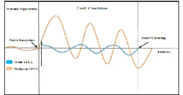
Fig .3.The Current Waveform With and Without SFCL during A Fault.
III.FAULT CURRENT LIMITER
Fig. 5 shows the circuit topology of the proposed FCL which is composed of the two following parts:
1) Bridge part that includes a diode rectifier bridge, a small dc limiting reactor. (Note that its resistance is involved too.), a semiconductor switch (IGBT or GTO), and a freewheeling diode.
2) Shunt branch as a compensator that consists of a resistor and an inductor.
Fig.5. Proposed FCL topology
The total power losses of the proposed structure become a very small percentage of the feeder’s transmitted power.
1) It is possible to placing a small reactor in series with the self turn off switch at dc side. This reactor plays two roles; Snubber for self turn off switch to protect it and current limiter at first moments of fault that will be discussed in detail.
2)In normal operation of power system, self turn off switch is ON and small dc reactor is charged to the peak of line current and behaves as short circuit. Neglecting small voltage drop on diodes and self turn off switch, total voltage drop on FCL becomes almost zero and therefore, FCL does not affect normal operation of power system. As fault occurs, dc reactor limits increasing rate of short circuit current and starts to charge. When the line current reaches to the pre-defined value that can be set by system operator, control system turns off the self turn off switch. So, the bridge retreats from utility. At this moment, free wheeling diode turns on and provides free path for discharging the dc reactor. When the bridge turns off, fault current passes through the resonance part of the proposed FCL.
current path. As will be shown in analytical analysis section, in such condition, fault current will has increasing variations. But, by using arrester fault current can be limited to a constant value. In addition, it is possible to protect the capacitor from over voltages that can be harmful
By removal of fault, self turn off switch turns on again and system returns to the normal state
IV. MATLAB/SIMULINK RESULTS Case 1: Active type SFCL
Fig.6.Matlab/Simulink Model of Proposed Distribution System with Distributed Generation Units without any compensation scheme using Active SFCL methodology, using Matlab/Simulink platform.
Fig.7.Voltage characteristics of the Bus-A under different locations of DG without SFCL.
Fig.8.Voltage characteristics of the Bus-A under different locations of DG with SFCL.
Fig.9. Line current waveforms when the three-phase short-circuit occur at k3 point without SFCL.
Fig.10. Line current waveforms when the three-phase short-circuit occur at k3 point with SFCL.
Fig.12. Active SFCL’s current-limiting performances under different fault locations at k2 point. Case 2: Active type FCL
Fig.13.Matlab/Simulink Model of Proposed Distribution System with Distributed Generation Units without any compensation scheme using Active
FCL methodology, using Matlab/Simulink platform.
Fig.14. Line current waveforms when the three-phase short-circuit occur at k3 point with FCL.
V.CONCLUSION
This paper is the quick review of Distributed Generation in India, its need, importance in near future. This paper provides how Traditional Generation is differing from Distributed Generation. In this paper, the application of the active SFCL and FCL into in a power distribution network with DG units is investigated. For the power frequency overvoltage caused by on the same problem using a
DG based operation to enhance the power quality concerns at bus levels using a supportive source with active SFCL and FCL topologies. A single-phase grounded fault, compare to the active type SFCL and active type FCL. Active type FCL is reduces the overvoltage’s amplitude and avoids damaging the relevant distribution equipment. The active FCL can as well suppress the short-circuit current induced by a three-phase grounded fault effectively, and the power system’s safety and reliability can be improved.
REFERENCES
[1] S. Conti, “Analysis of distribution network protection issues in presence of dispersed generation,” Elect. Power Syst. Res., vol. 79, no. 1, pp. 49–56, Jan. 2009.
[2] S.-Y. Kim and J.-O. Kim, “Reliability evaluation of distribution network with DG considering the reliability of protective devices affected by SFCL,”
IEEE Trans. Appl. Supercond., vol. 21, no. 5, pp. 3561–3569, Oct. 2011.
[3] S. A. A. Shahriari, A. Yazdian, and M. R. Haghifam, “Fault current limiter allocation and sizing in distribution system in presence of distributed generation,” in Proc. IEEE Power Energy Soc. Gen. Meet., Calgary, AB, Canada, Jul. 2009, pp. 1–6. [4] S.-H. Lim, J.-S. Kim, M.-H. Kim, and J.-C. Kim, “Improvement of protection coordination of protective devices through application of a SFCL in a power distribution system with a dispersed generation,” IEEE Trans. Appl. Supercond., vol. 22, no. 3, p. 5601004, Jun. 2012.
[5] L. Chen, Y. Tang, J. Shi, and Z. Sun, “Simulations and experimental analyses of the active superconducting fault current limiter,” Phys. C, vol. 459, no. 1/2, pp. 27–32, Aug. 2007.
[6] L. Chen, Y. Tang, J. Shi, Z. Li, L. Ren, and S. Cheng, “Control strategy
for three-phase four-wire PWM converter of integrated voltage compensation type active SFCL,”
Phys. C, vol. 470, no. 3, pp. 231–235, Feb. 2010. [7] L. Chen, Y. J. Tang, J. Shi, L. Ren, M. Song, S. J. Cheng, Y. Hu, and X. S. Chen, “Effects of a voltage compensation type active superconducting fault current limiter on distance relay protection,” Phys. C, vol. 470, no. 20, pp. 1662–1665, Nov. 2010.