ISSUE 3 STOCK # 0233085
Wireless System Manual
The information contained in this document is specific to Dterm Series E only.
Minimum firmware may be required. Contact NEC Engineering for additional information.
NEC America, Inc. reserves the right to change the specifications, functions, or features, at any time, without notice.
NEC America, Inc. has prepared this document for use by its employees and customers. The information contained herein is the property of NEC America, Inc. and shall not be reproduced without prior written approval from NEC America, Inc.
NEAX and Dterm are registered trademarks of NEC Corporation.
Copyright 1998, 1999, 2000
NEC America, Inc.
ISSUE 1 ISSUE 2 ISSUE 3 ISSUE 4 DATE NOVEMBER, 1998 DATE JULY, 1999 DATE AUGUST, 2000 DATE
ISSUE 5 ISSUE 6 ISSUE 7 ISSUE 8
DATE DATE DATE DATE
NEAX2400 IMX
1 2 3 4 5 6 7 8
i 1 2 3
ii 1 2 3
iii 1 2 3
iv 1 2 3
v 1 2 3
vi 1 2 3
vii 1 2 3
viii 1 2 3
ix 1 2 3
x 1 2 3
1 1 2 3
2 1 2 3
3 1 2 3
4 1 2 3
5 1 2 3
6 1 2 3
7 1 2 3
8 1 2 3
9 1 2 3
10 1 2 3
11 1 2 3
12 1 2 3
13 1 2 3
14 1 2 3
15 1 2 3
16 1 2 3
17 1 2 3
18 1 2 3
19 1 2 3
20 1 2 3
21 1 2 3
22 1 2 3
23 1 2 3
24 1 2 3
25 1 2 3
26 1 2 3
27 1 2 3
28 1 2 3
29 1 2 3
30 1 2 3
31 1 2 3
32 1 2 3
33 1 2 3
34 1 2 3
35 1 2 3
36 1 2 3
37 1 2 3
38 1 2 3
39 1 2 3
40 1 2 3
41 1 2 3
42 1 2 3
43 1 2 3
44 1 2 3
45 1 2 3
46 1 2 3
47 1 2 3
48 1 2 3
49 1 2 3
50 1 2 3
51 1 2 3
52 1 2 3
53 1 2 3
54 1 2 3
55 1 2 3
56 1 2 3
57 1 2 3
58 1 2 3
59 1 2 3
60 1 2 3
61 1 2 3
62 1 2 3
63 1 2 3
64 1 2 3
65 1 2 3
66 1 2 3
67 1 2 3
68 1 2 3
69 1 2 3
70 1 2 3
71 1 2 3
72 1 2 3
73 1 2 3
74 1 2 3
75 1 2 3
76 1 2 3
77 1 2 3
78 1 2 3
79 1 2 3
80 1 2 3
81 1 2 3
82 1 2 3
83 1 2 3
84 1 2 3
85 1 2 3
86 1 2 3
87 1 2 3
88 1 2 3
89 1 2 3
90 1 2 3
91 1 2 3
92 1 2 3
93 1 2 3
94 1 2 3
95 1 2 3
96 1 2 3
97 1 2 3
98 1 2 3
99 1 2 3
100 1 2 3
101 1 2 3
1 2 3 4 5 6 7 8
105 1 2 3
106 1 2 3
107 1 2 3
108 1 2 3
109 1 2 3
110 1 2 3
111 1 2 3
112 1 2 3
113 1 2 3
114 1 2 3
115 1 2 3
116 1 2 3
117 1 2 3
118 1 2 3
119 1 2 3
120 1 2 3
121 1 2 3
122 1 2 3
123 1 2 3
124 1 2 3
125 1 2 3
126 1 2 3
127 1 2 3
128 1 2 3
129 1 2 3
130 1 2 3
131 1 2 3
132 1 2 3
133 1 2 3
134 1 2 3
135 1 2 3
136 1 2 3
137 1 2 3
138 1 2 3
139 1 2 3
ISSUE 1 ISSUE 2 ISSUE 3 ISSUE 4 DATE NOVEMBER, 1998 DATE JULY, 1999 DATE AUGUST, 2000 DATE
ISSUE 5 ISSUE 6 ISSUE 7 ISSUE 8
DATE DATE DATE DATE
NEAX2400 IMX
143 1 2 3
144 1 2 3
145 1 2 3
146 1 2 3
147 1 2 3
148 1 2 3
149 1 2 3
150 1 2 3
151 1 2 3
152 1 2 3
153 1 2 3
154 1 2 3
155 1 2 3
156 1 2 3
157 1 2 3
158 1 2 3
159 1 2 3
160 1 2 3
161 1 2 3
162 1 2 3
163 1 2 3
164 1 2 3
165 1 2 3
166 1 2 3
167 1 2 3
168 1 2 3
169 1 2 3
170 1 2 3
171 1 2 3
172 1 2 3
173 1 2 3
174 1 2 3
175 1 2 3
176 1 2 3
177 1 2 3
178 1 2 3
179 1 2 3
180 1 2 3
1 2 3 4 5 6 7 8
181 1 2 3
182 1 2 3
183 1 2 3
184 1 2 3
185 1 2 3
186 1 2 3
187 1 2 3
188 1 2 3
189 1 2 3
190 1 2 3
191 1 2 3
192 1 2 3
193 1 2 3
194 1 2 3
195 1 2 3
196 1 2 3
197 1 2 3
198 1 2 3
199 1 2 3
200 1 2 3
201 1 2 3
202 1 2 3
203 1 2 3
204 1 2 3
205 1 2 3
206 1 2 3
207 1 2 3
208 1 2 3
209 1 2 3
210 1 2 3
211 1 2 3
212 1 2 3
213 1 2 3
214 1 2 3
215 1 2 3
216 1 2 3
217 1 2 3
218 1 2 3
219 1 2 3
220 1 2 3
221 1 2 3
222 1 2 3
223 1 2 3
224 1 2 3
225 1 2 3
226 1 2 3
227 1 2 3
228 1 2 3
229 1 2 3
230 1 2 3
231 2 3
232 2 3
233 2 3
234 2 3
235 2 3
236 2 3
237 2 3
238 2 3
239 2 3
240 2 3
241 2 3
242 2 3
243 2 3
244 2 3
245 2 3
246 2 3
247 2 3
248 2 3
249 2 3
250 2 3
251 2 3
252 2 3
253 2 3
1 2 3 4 5 6 7 8
257 2 3
258 2 3
259 2 3
260 2 3
261 2 3
262 2 3
263 2 3
264 2 3
265 2 3
266 2 3
267 3 268 3 269 3 270 3 271 3 272 3 273 3 274 3 275 3 276 3 277 3 278 3 279 3 280 3 281 3 282 3 283 3 284 3 285 3 286 3 287 3 288 3 289 3 290 3 291 3
ISSUE 1 ISSUE 2 ISSUE 3 ISSUE 4 DATE NOVEMBER, 1998 DATE JULY, 1999 DATE AUGUST, 2000 DATE
ISSUE 5 ISSUE 6 ISSUE 7 ISSUE 8
DATE DATE DATE DATE
NEAX2400 IMX
295 3
296 3
297 3
298 3
299 3
300 3
301 3
302 3
303 3
304 3
305 3
306 3
307 3
308 3
309 3
310 3
311 3
312 3
313 3
314 3
315 3
316 3
317 3
318 3
319 3
320 3
321 3
322 3
323 3
324 3
325 3
326 3
ISSUE 3 AUGUST, 2000
NEAX2400 IMX
Wireless System Manual
TABLE OF CONTENTS
Page
LIST OF FIGURES . . . v
LIST OF TABLES . . . vii
CHAPTER 1 GENERAL DESCRIPTION . . . 1
1. GENERAL DESCRIPTION OF SYSTEM. . . 1
2. CONNECTION BETWEEN CSINT AND ZT . . . 3
3. MOVEMENT OF PS IN NEAX2400 IMX. . . 4
4. SYSTEM CAPACITY . . . 6
5. MOUNTING LOCATION OF CSINT CIRCUIT CARD . . . 6
6. FUNCTIONS/MOUNTING CONDITIONS OF CIRCUIT CARDS . . . 7
7. SERVICE CONDITIONS. . . 9
8. LIST OF SERVICE FEATURES . . . 10
CHAPTER 2 INSTALLATION DESIGN . . . 23
1. INSTALLATION. . . 23
1.1 ZT (ZONE TRANSCEIVER) AND ITS CONNECTION WITH S INTERFACE . . . 23
1.2 ZT (ZONE TRANSCEIVER) AND ITS CONNECTION WITH U INTERFACE . . . 28
1.3 BASIC KNOWLEDGE ON ZT INSTALLATION. . . 30
2. INSTALLATION PROCEDURE OF ZONE TRANSCEIVER (ZT) . . . 35
3. SYSTEM START-UP . . . 42
CHAPTER 3 CIRCUIT CARDS . . . 43
PA-4CSIC (CSINT): ZT (ZONE TRANSCEIVER) INTERFACE . . . 44
PA-4CSID (CSINT): ZT (ZONE TRANSCEIVER) INTERFACE . . . 55
PA-4CSIE (CSINT): ZT (ZONE TRANSCEIVER) INTERFACE . . . 65
PA-4CSIF (CSINT): ZT (ZONE TRANSCEIVER) INTERFACE . . . 74
PA-CK16 (WCS): SYNCHRONOUS SIGNAL TRANSMISSION CIRCUIT FOR CS/ZT . . . 84
Page
AUTOMATIC ANNOUNCEMENT-PS OUT OF ZONE/C.F.-PS INCOMING INCOMPLETE . . . 108
AUTOMATIC ANNOUNCEMENT-DISCONNECTED PS OUT OF ZONE . . . 113
NAME DISPLAY . . . . . 116
NAME DISPLAY - CCIS . . . 119
NUMBER SHARING . . . 122
PCS ROAMING. . . . . . 125
TTC Q.931A PROTOCOL TIE LINE WITH PCS ROAMING . . . 132
TWO-LINE OPERATION . . . 156
VOICE MAIL INDICATION (VMI) . . . 158
ZT PROGRAM DOWNLOAD . . . 159
CALL FORWARDING - DROPPED CALLS . . . 161
DATA COMMUNICATIONS - 32 KBPS . . . 165
BEARER CAPABILITY . . . 166
AUTHORIZATION CODE . . . 168
CALL PARK . . . . . . 172
GROUP CALL-AUTOMATIC CONFERENCE (20-PARTY) . . . 175
SHORT TEXT MESSAGE SERVICE . . . 185
CHAPTER 5 COMMANDS . . . 187
1. COMMAND DESCRIPTION AND DATA SHEET FOR ASSIGNMENT . . . 189
ACSDL : ASSIGNMENT OF CS/ZT DATA FOR LOCAL DATA MEMORY . . . 190
ACSDN : ASSIGNMENT OF CS/ZT DATA FOR NETWORK DATA MEMORY . . . 192
ACSEL : ASSIGNMENT OF EXPANSION CS/ZT SYSTEM DATA FOR LOCAL DATA MEMORY . . . 195
ACSEN : ASSIGNMENT OF EXPANSION CS/ZT SYSTEM DATA FOR NETWORK DATA MEMORY . . . 197
ACSPL : ASSIGNMENT OF CS/ZT PEG COUNT DATA FOR LOCAL DATA MEMORY . . . 199
AHRTL : ASSIGNMENT OF HOME PBX ROUTING NUMBER DATA FOR LOCAL DATA MEMORY . . . 200
ALVPL : ASSIGNMENT OF LVP CODE FOR LOCAL DATA MEMORY. . . 202
ALVPN : ASSIGNMENT OF LVP CODE FOR NETWORK DATA MEMORY . . . 206
APCNL : ASSIGNMENT OF PHS COMMUNITY NUMBER DATA FOR LOCAL DATA MEMORY . . . 208
APCNN : ASSIGNMENT OF PHS COMMUNITY NUMBER DATA FOR NETWORK DATA MEMORY . . . 211
APDLL : DOWNLOAD OF PS OPERATION DATA FOR LOCAL DATA MEMORY . . . 216
APDLN : DOWNLOAD OF PS OPERATION DATA FOR NETWORK DATA MEMORY . . . 221
APSD : ASSIGNMENT OF PS OPERATION DATA FOR DM . . . 225
ARODL : ASSIGNMENT OF ROAMING SELF PBX NUMBER FOR LOCAL DATA MEMORY. . . 233
AVPD : ASSIGNMENT OF VISITOR PS DATA . . . 235
AVPDL : ASSIGNMENT OF TELEPHONE NUMBER FOR VISITOR PS FOR LOCAL DATA MEMORY . . . 237
AVPDN : ASSIGNMENT OF TELEPHONE NUMBER FOR VISITOR PS FOR NETWORK DATA MEMORY . . . 239
ASFC : ASSIGNMENT OF SERVICE FEATURE RESTRICTION CLASS . . . 241
ASPA : ASSIGNMENT OF SPECIAL ACCESS CODE . . . 244
ASYD : ASSIGNMENT OF SYSTEM DATA. . . 248
Page
ALGNL : ASSIGNMENT OF TELEPHONE NUMBER DATA FOR LOCAL DATA MEMORY . . . . 256
ALGNN : ASSIGNMENT OF TELEPHONE NUMBER DATA FOR NETWORK DATA MEMORY. 258 ALGSL : ASSIGNMENT OF TELEPHONE NUMBER DATA FOR LOCAL DATA MEMORY . . . . 260
ALGSN : ASSIGNMENT OF TELEPHONE NUMBER DATA FOR NETWORK DATA MEMORY. 264 ALRTN : ASSIGNMENT OF LOGICAL ROUTE FOR NETWORK DATA MEMORY . . . 268
ANSDL : ASSIGNMENT OF NUMBER SHARING DATA FOR LOCAL DATA MEMORY . . . 270
ANSDN : ASSIGNMENT OF NUMBER SHARING DATA FOR NETWORK DATA MEMORY. . . . 273
APMD : ASSIGNMENT OF TRUNK LINE APPEARANCE MAXIMUM NECESSARY DIGIT FOR DM . . . 276
APMLL : ASSIGNMENT OF PS MULTILINE DATA FOR LOCAL DATA MEMORY . . . 278
APMLN : ASSIGNMENT OF PS MULTILINE DATA FOR NETWORK DATA MEMORY. . . 280
APSP : ASSIGNMENT OF TRUNK LINE APPEARANCE FOR DM . . . 282
AZDL : ZT PROGRAM DOWNLOAD. . . 284
AHLG : ASSIGNMENT OF CFT HOT LINE GROUP . . . 286
AHLGL : ASSIGNMENT OF CFT HOT LINE GROUP FOR LDM . . . 288
AHLGN : ASSIGNMENT OF CFT HOT LINE GROUP FOR NDM . . . 290
2. COMMANDS FOR OPERATION AND MAINTENANCE . . . 292
ATRF : ASSIGNMENT OF TRAFFIC MEASUREMENT ORDER . . . 293
AZARL : ASSIGNMENT OF ZT AREA INFORMATION FOR LOCAL DATA MEMORY . . . 294
AZARN : ASSIGNMENT OF ZT AREA INFORMATION FOR NETWORK DATA MEMORY. . . 295
COCS1L : CONTROL OF CS/ZT STATUS READ FOR LOCAL DATA MEMORY . . . 296
COCS1N : CONTROL OF CS/ZT STATUS READ FOR NETWORK DATA MEMORY . . . 297
COCS2L : CHANGE OF CS/ZT OPERATION PARAMETER FOR LOCAL DATA MEMORY . . . 298
COCS2N : CHANGE OF CS/ZT OPERATION PARAMETER FOR NETWORK DATA MEMORY. . 299
COCS3L : CHANGE OF CS/ZT RESET FOR LOCAL DATA MEMORY . . . 300
COCS3N : CONTROL OF CS/ZT RESET FOR NETWORK DATA MEMORY . . . 301
DLIN : DISPLAY OF A LIST OF ROAMING PS . . . 302
DPSN : DISPLAY OF PS STATION DATA. . . 303
DRPS : DISPLAY FOR REVERSE DEVELOP PS DATA . . . 305
DTFP : DISPLAY OF CS/ZT PEG COUNT DATA . . . 306
DPSN : DISPLAY OF PS STATION DATA. . . 307
DTFP : DISPLAY OF CS/ZT PEG COUNT DATA . . . 309
MBCSL : MAKE BUSY OF CS/ZT FOR LOCAL DATA MEMORY . . . 310
MBCSN : MAKE BUSY OF CS/ZT FOR NETWORK DATA MEMORY. . . 311
CHAPTER 6 SYSTEM OPERATION AND MAINTENANCE . . . 313
1. CSINT CIRCUIT CARD MAKE-BUSY SET/CANCEL . . . 313
2. ZT PEG COUNT FOR TRAFFIC CONTROL . . . 315
3. DISPLAY OF PS STATION DATA . . . 318
Figure Title Page
Figure 1-1 Route Connecting Diagram : Built-in PCS System . . . 1
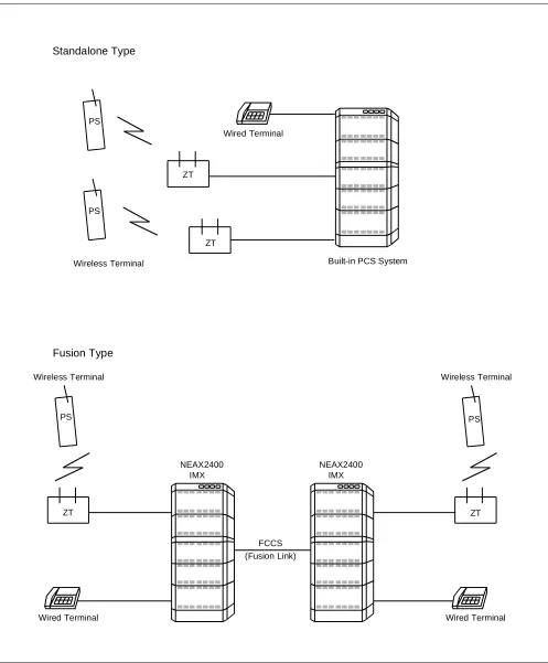
Figure 1-2 Comparison : Standalone Type and Fusion Type . . . 2
Figure 1-3 Power Supply from the Built-in PCS System . . . 3
Figure 1-4 Local Power Supply . . . 3
Figure 1-5 Route Connection Diagram : U Interface (When NT1 is used) . . . 3
Figure 2-1 Related Equipment for Built-in PCS System (When using PA-4CSIC) . . . 24
Figure 2-2 Related Equipment for Built-in PCS System (When using PA-4CSIE) . . . 26
Figure 2-3 Standard Installation Image . . . 30
Figure 2-4 High Traffic Installation Image . . . 30
Figure 2-5 Image of ZT Installation . . . 31
Figure 2-6 Example of Inappropriate Mounting . . . 35
Figure 2-7 Dimension Drawing for ZT Installation (1/2) . . . 36
Figure 2-8 Dimension Drawing for ZT Installation (2/2) . . . 37
Figure 2-9 Mounting of the ZT . . . 38
Figure 2-10 Local Power Feeding . . . 38
Figure 2-11 LEDs on the Zone Transceiver . . . 40
Figure 2-12 Adjustment of Antenna . . . 41
Figure 3-1 Location of Card in System . . . 44
Figure 3-2 Lamp, Key and Connectors : PA-4CSIC . . . 45
Figure 3-3 LT Connector Leads Accommodation of PIM : PA-4CSIC . . . 53
Figure 3-4 Connecting Route Diagram . . . 54
Figure 3-5 Location of Card in System . . . 55
Figure 3-6 Lamp, Key and Connectors : PA-4CSID . . . 56
Figure 3-7 LT Connector Leads Accommodation of PIM : PA-4CSID . . . 63
Figure 3-8 Connecting Route Diagram . . . 64
Figure 3-9 Location of Card in System . . . 65
Figure 3-10 Lamp, Key and Connectors : PA-4CSIE . . . 66
Figure 3-11 LT Connector Leads Accommodation of PIM : PA-4CSIE . . . 72
Figure 3-12 Connecting Route Diagram . . . 73
Figure 3-13 Location of Card in System . . . 74
Figure 3-14 Lamp, Key and Connectors : PA-4CSIF . . . 75
Figure 3-15 LT Connector Leads Accommodation of PIM : PA-4CSIF . . . 82
Figure 3-16 Connecting Route Diagram . . . 83
Figure 3-17 Location of PA-CK16 [SYNC (WCS)] Card in the System . . . 84
Figure 3-18 Face Layout of PA-CK16 . . . 85
Figure 3-19 LT Connector Lead Accommodation (1/2) . . . 88
Figure 3-19 LT Connector Lead Accommodation (2/2) . . . 89
Figure 3-20 Connecting Route Diagram . . . 90
Figure 3-21 Example of Clock Network Using PA-CK16 [SYNC (WCS)] . . . 91
Figure Title Page
Table Title Page
Table 1-1 System Capacity. . . . 6
Table 1-2 List of PCS Features . . . 10
Table 1-3 List of OG Call Features . . . 12
Table 1-4 List of IC Call Features . . . 12
Table 1-5 List of Station Service Features . . . 14
Table 1-6 List of Other Service Features . . . 16
Table 1-7 List of Attendant Console Service Features . . . 17
Table 1-8 List of Network Service Features . . . 19
Table 1-9 List of Operation/Maintenance Service Features . . . 19
Table 1-10 List of ISDN Service Features . . . 20
Table 1-11 List of CCIS Features . . . 21
Table 2-1 Meaning of LED Indications . . . 39
Table 3-1 Switch Setting Table . . . 52
Table 3-2 PA-CK16 Lamp Indications Reference . . . 86
Table 3-3 Standard Switch Settings . . . 87
Table 4-1 Roaming Class Data List . . . 130
Table 4-1 Roaming Class Data List (Continued) . . . 131
Table 4-2 List of OG Call Features for Q.931a . . . 134
Table 4-3 List of IC Call Features for Q.931a. . . 134
Table 4-4 List of Station Service Features for Q.931a . . . 136
Table 4-5 List of Other Service Features for Q.931a . . . 140
Table 4-6 List of Attendant Console Service Features for Q.931a . . . 141
Table 4-7 List of Network Service Features for Q.931a . . . 143
Table 4-8 List of Operation/Maintenance Service Features for Q.931a . . . 143
Table 4-9 List of ISDN Service Features for Q.931a . . . 144
Table 4-10 List of CCIS Service Features for Q.931a . . . 145
Table 4-11 Route Class Data Assignment Table for Q.931a . . . 149
Table 5-1 List of Commands. . . 187
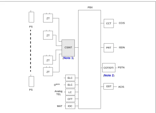
1. GENERAL DESCRIPTION OF SYSTEM
The Built-in PCS System has its CSINT, which interfaces the ZT with the system, mounted in the Port Interface Module (PIM). The Control Processor Rack (CPR) exclusively designed for the PCS is necessary in the PBX. Figure 1-1 shows the entire route connecting diagram of this system.
Module structures of the Built-in PCS System are identical to that of the PBX. For more details, see the “Installation Design Manual”.
ZT
ZT
ZT
ZT
PRT
ODT PBX
PS
PS
Analog TEL
MAT
ISDN CCT CCIS
PSTN CSINT
ELC ELC
LC
CFT
IOC
ACIS COT/DTI
Dterm
(Note 1)
Figure 1-2 Comparison : Standalone Type and Fusion Type
Wired Terminal
Standalone Type
Wired Terminal
Built-in PCS System Wireless Terminal
Wireless Terminal
Wired Terminal Wireless Terminal
NEAX2400 IMX
FCCS (Fusion Link) Fusion Type
NEAX2400 IMX PS
ZT PS
ZT
ZT ZT
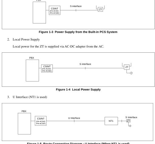
2. CONNECTION BETWEEN CSINT AND ZT
Figures 1-3 through 1-5 illustrate connection methods between the CSINT and the ZT. The CSINT and the ZTs can be connected with two pairs of twisted cable using the following two connection methods - one, line voltage from the Built-in PCS System and the other, the local power supply.
1. PBX line power from Built-in PCS System.
Line Power from the PCS System is power to the ZT supplied from the PBX.
Figure 1-3 Power Supply from the Built-in PCS System 2. Local Power Supply
Local power for the ZT is supplied via AC-DC adapter from the AC.
Figure 1-4 Local Power Supply 3. U Interface (NT1 is used)
S interface PBX
CSINT
(PA-4CSIC ZT
/PA-4CSIE)
S interface PBX
CSINT
(PA-4CSIC ZT
/PA-4CSIE)
3. MOVEMENT OF PS IN NEAX2400 IMX
PCS COMMUNITY
The SYS-ID is a unique ID which was given to manage the PCS system. The area where the SYS-ID is effective is called PCS Community. Every PCS Community in a Fusion network is given a unique PHS Community Number (PCN). Each PCN has its own SYS-ID. The PCN is used in stead of the SYS-ID for MAT command, and this can reduce the effect upon changing the SYS-ID to some measure. The habitual operation of the SYS-ID, which reaches to nine digits for the management purpose, is not needed; therefore easy maintenance can be provided. A single PCS Community can be assigned in multiple nodes, and a single node can belong to multiple PCS Communities by using the Tenant service.
PS movement in the system is classified into three kinds as described below:
1. Stand-by condition movement
Movement of an idle PS within the home PCN area in the home Fusion network (in the Fusion network accommodating the home node). The event of PS Location Registration occurs only when the PS moves over the Calling area. Even if a PS is in Roaming status, movement of the PS within the current visitor node is also stand-by condition movement. In the system, the home PCN can be assigned over the node, however the Calling Area cannot. Because of this, the event of PS Location Registration occurs whenever an idle PS moves over the node.
2. Hand-Over
Movement of a PS engaged in communication within the home PCN area in the home Fusion network. The event of Hand-Over occurs regardless of the Calling Area.
Even if a PS is in the Roaming status, movement of the PS engaged in communication within the current visitor node is also Hand-Over. In the system, the call engaged in communication is supported even in the case of Hand-Over over the node.
3. Roaming
Fusion-I A B C D Home PCN-a Home PCN-b Fusion-II E F Visit PCN-c Visit PCN-d G
Node-W Node-X Node-Y Node-Z
FCCS Q. 931a or IS-11572 Note
FCCS A, B Home Node Home PCN C, D Visit Node Home PCN E Visit Fusion Visit Node Visit PCN F Visit Fusion Other Node Visit PCN G Yet Other Fusion A, B Home Node Home PCN Stand-by condition Movement H-O Stand-by condition Movement H-O
Roaming Cannot move Cannot move
C, D Visit Node Home PCN Stand-by condition Movement H-O Stand-by condition Movement H-O
Cannot move Cannot move Cannot move
E Visit Fusion
Visit Node Visit PCN
Roaming Cannot move Stand-by condition
Movement H-O Stand-by condition Movement H-O Cannot move F Visit Fusion
Cannot move Cannot move Stand-by condition
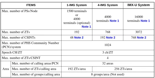
4. SYSTEM CAPACITY
The following explains the capacity of the System.
Note 1: Depending on capacity of NDM/LDM.
When upgrading from ICS and re-using Data Memory, Maximum 2000 terminals/Node.
Note 2: A maximum of 12 circuit cards can be mounted in a PIM. 5. MOUNTING LOCATION OF CSINT CIRCUIT CARD
CSINT circuit card can be mounted in any universal slot in the PIM. Table 1-1 System Capacity
ITEMS 1-IMG System 4-IMG System IMX-U System
Max. number of PSs/Node 1500 terminals or 4000 terminals (optional)
Note 1
4000 terminals Note 1
16000 terminals Note 1
Max. number of ZTs 192 768 3072
Max. number of CSINTs 48 Note 2 192 Note 2 768 Note 2
Max. number of PHS Community Number
(PCN)/system 1024
Speech CH/ZT 3 ch/ZT
Max. number of ZTs/CSINT 4
Area
Max. number of calling areas/PCN 32 areas
Max. number of ZTs/calling area 192 ZTs/area 256 ZTs/area
6. FUNCTIONS/MOUNTING CONDITIONS OF CIRCUIT CARDS
The following circuit cards are necessary when using the system.
1. Universal LC/TRK circuit cards
ABBREVIATION CIRCUIT
CARD NAME FUNCTIONS AND MOUNTING CONDITIONS
RST PA-8RSTJ/
PA-8RSTM
Register-Sender
As is the case with the RST functions in the normal stations, the RST is used virtually, and estimating how many lines are needed is as important as considering the number of terminals.
Refer to the “Circuit Card Manual” for SW setting.
DAT PA-4DATA/
PA-4DATB
Announcement Trunk
Used for ANNOUNCEMENT-PS OUT OF ZONE. Refer to the “Circuit Card Manual” for SW setting.
TSW PH-SW10
(1-IMG System)
Synchronized with the digital circuit cards such as PRT/DTI in a variety of combinations. (Standard precision clock oscillator) This card is
synchronized with clocks generated from the PRT/DTI, thus supplying the necessary clock signal to the system.
Number of clock input route: DTI: 4, DCS: 2
Functions: Burst Cyclic Generator of 5ms which supplies clock signaling to ZT.
Refer to the “Circuit Card Manual” for SW setting and wiring.
OSC PA-CK14
(1-IMG System)
Synchronized with the digital circuit cards such as PRT/DTI in a variety of combinations. (High precision clock oscillator) This is synchronized with clocks generated from the PRT/DTI, thus supplying the necessary clock signal to the system.
Number of clock input route: DTI: 4, DCS: 2
Functions: Burst Cyclic Generator of 5ms which supplies clock signaling to ZT.
Refer to the “Circuit Card Manual” for SW setting.
PLO PH-CK16/
PH-CK16-A (Other than 1-IMG System)
Synchronized with the digital circuit cards such as PRT/DTI in a variety of combinations. (Standard precision clock oscillator) This card is
synchronized with clocks generated from the PRT/DTI, thus supplying the necessary clock signal to the system.
Number of clock input route: DTI: 4, DCS: 2
CLK PH-CK18 (IMX-U System)
This card is used for the Local Node of the IMX-U system. This card receives clock signals from the Phase Lock Oscillator (PLO) accommodated in TSWM0 of IMG1, distributing the following signals to Time Division Switch (TSW) accommodated in TSWM1 of IMG2.
• 32.768 MHz CLK • 8 KHz FH
• 5 msecדn” FH
CSINT PA-4CSIC This is an LC circuit card which provides interface with the Zone Transceiver (ZT). A maximum of four ZTs can be connected to one circuit card. Interface of the ZT corresponds to ISDN standards, but multi-point connection with the ZTs is not available.
• I.430, Q. 921 interface
• B channel is used for two channels of 32 kbps each with a total speed of 64 kbps in the 2B+D.
PA-4CSID This is an LC circuit card which provides interface with the Zone Transceiver (ZT). A maximum of four ZTs can be accommodated to one circuit card. NT1 is used in connecting the ZTs. Interface with NT1 corresponds to U Reference point of ISDN standards of the Echo canceller method.
• ANSI T1.601 interface is used
• B channel is used for two channels, each with a transmission speed of 32 kbps, with a total of 64 kbps. (2B+D)
• Functions as a Sealing Currency supplier to the NT1 (Maximum 15 mA to protect cables from rusting)
PA-4CSIE This is an LC circuit card which provides interface with the Zone Transceiver (ZT). A maximum of four ZTs can be connected to one circuit card. Interface of the ZT corresponds to ISDN standards, but multi-point connection with the ZTs is not available.
• I.430, Q. 921 interface
• B channel is used for two channels of 32 kbps each with a total speed of 64 kbps in the 2B+D.
PA-4CSIF This is an LC circuit card which provides interface with the Zone Transceiver (ZT). A maximum of four ZTs can be connected to one circuit card. Interface with NT1 corresponds to U Reference point of ISDN standards of the Echo canceller method.
• ANSI T1.601 interface is used
• B channel is used for two channels of 32 kbps each with a total of 64 kbps in the 2B+D.
• Functions as a Sealing Currency supplier to the NT1 (Maximum 15 mA to protect cables from rusting) CFT PA-CFTB 8-Party Conference Trunk
Used SP388 (firmware) for GROUP CALL-AUTOMATIC CONFERENCE Used SP1141 (firmware) for GROUP CALL-AUTOMATIC
CONFERENCE (20-party).
Refer to the “Circuit Card Manual” for SW setting. ABBREVIATION CIRCUIT
7. SERVICE CONDITIONS
Below are some of the conditions for using the System.
1. The system is available in the Business/Hotel System.
2. ACD/OAI services are incompatible with the system.
3. The following software is necessary for system operation.
Basic software: Series 7300 or later
Optional software: Service (Application) software including PCS service. Note
Note: When using PCS in Fusion Network, this software must be installed in all nodes. Even if no PSs are ac-commodated in a node, this software must be installed in the node.
4. SMDR equipment can be used for billing.
5. The following billing services are available in the system.
6. PS is not connected to the data terminal equipment.
7. PS station number cannot be programmed on the feature key of Dterm (as a Multi-Line).
8. SID TO TERMINATING USER-DISPLAY/ANALOG CALLER ID service features are not available for PS.
9. Service conditions for CCIS features are as follows:
(a) When a call is originated from or terminated to a PS via CCIS, the calling number sent to the called
FEATURE NAME REMARKS
SMDR for outgoing C.O. line
SMDR for incoming C.O. line
SMDR for outgoing Tie line
SMDR for incoming Tie line
SMDR for incoming DID
SMDR for DIT
8. LIST OF SERVICE FEATURES
1. PCS Feature
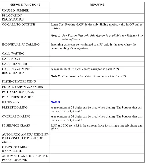
Table 1-2 List of PCS Features
SERVICE FUNCTIONS REMARKS
UNUSED NUMBER
PS LOCATION REGISTRATION
OG CALL TO OUTSIDE Least Cost Routing (LCR) is the only dialing method valid in OG call to outside.
Note 1: For Fusion Network, this feature is available for Release 3 or later software.
INDIVIDUAL PS CALLING Incoming calls can be terminated to a PS only in the area where the corresponding PS is registered.
CALL WAITING
CALL HOLD
CALL TRANSFER
CALLING ZT ZONE REGISTRATION
A maximum of 32 areas can be assigned in each PCN.
Note 2: One Fusion Link Network can have PCN 1 ~ 1024. DISTINCTIVE RINGING
PB (DTMF) SIGNAL SENDER
PS-TO-STATION CALL
PS AUTHENTICATION
HANDOVER Note 3
PRESET DIALING A maximum of 24 digits can be used when dialing. The buttons that can be used are: 0-9, # and *.
OVERLAP DIALING A maximum of 24 digits can be used when dialing. The buttons that can be used are: 0-9, # and *.
PS SERVICE CLASS RSC and SFC for a PS is the same as those for a single line telephone and Dterm.
AUTOMATIC ANNOUNCEMENT-DISCONNECTED PS OUT OF ZONE
C.F.-PS INCOMING INCOMPLETE
Note 3: Handover
1) If a PS user moves to another zone that has all speech channels busy, the PS remains connected to the original ZT.
2) Speech is temporarily interrupted during handover.
3) PS is unable to hand over in the following cases:
• When digits are being sent (BT is heard.)
• When a PS user attempts to hand over while connected to an operator (Attendant Console). BT is heard.
• When user C who has set Call Waiting to user A attempts to hand over while users A and B are talking. For details, see the following table.
• When a PS user is calling.
4) When using Fusion Link Network, PS can hand-over to another node as long as the destination node uses the same PCN.
2. PBX functions are available in the Built-in PCS System.
Tables 1-3 through 1-11 show functions available in the Built-in PCS System. Some of the following functions not available in this system are:
• Dterm function • OAI-ACD functions • OAI functions • Data functions
PS TERMINAL A PS TERMINAL B PS TERMINAL C
PS terminal A Call Waiting Tone (CWT)
Released (BT) Ring Back Tone (RBT)
PS terminal B Talking with PS C Released (BT) Talking with PS A
PS terminal C Talking with PS B Talking with PS A Released (BT) STATUS
Table 1-3 List of OG Call Features
×: Available : Conditionally available –: Not available/Not used
NAME OF SERVICE FEATURES
Standalone Fusion
REMARKS From PS To PS From PS To PS
ALTERNATE ROUTING/ROUTE
ADVANCE × – – –
SPEED CALLING-STATION/
GROUP – – – –
To be substituted for the memory dial of PS
SPEED CALLING-SYSTEM – – – –
TOLL CALL RESTRICTION × – – –
PUSH-BUTTON TO ROTARY
CONVERSION – – – –
PRIMARY CODE RESTRICTION × – – –
OG TRUNK QUEUING – – – –
OFF HOOK QUEUING – – – –
MISCELLANEOUS TRUNK RESTRICTION/ RESTRICTION FROM OG CALL
× – – –
Table 1-4 List of IC Call Features
×: Available : Conditionally available –: Not available/Not used
NAME OF SERVICE FEATURES Standalone Fusion REMARKS From PS To PS From PS To PS
EXTERNAL MUSIC-ON-HOLD – – – –
ATTENDANT CONSOLE × × × ×
DIT – × – × Note 1
SLUMBER TIME - DO NOT
DISTURB – – – –
POWER FAILURE TRANSFER
– – – – PS cannot be used for the Night station
DISTINCTIVE RINGING
– × – × Available in the D
term PS or
Dterm PSII Note 2
REMOTE ACCESS TO SYSTEM/
AUTOMATED ATTENDANT – × – ×
Note 3
TENANT SERVICE × × – –
Note 1: When a PS is assigned as the target station of DIRECT IN TERMINATION (DIT).
1) When the PS is Out of Zone (Out of Zone or in a state of POWER OFF), RBT is heard by the calling party.
If AUTOMATIC ANNOUNCEMENT-PS OUT OF ZONE is assigned by the PS, the calling party does not hear the Out of Zone Announcement, and instead hears RBT.
2) If a PS user moves Out of Zone while connected to an outside party, AUTOMATIC ANNOUNCEMENT-DISCONNECTED PS OUT OF ZONE cannot be heard by the outside party, but instead BT is heard.
3) When a PS is engaged and an outside call attempts CALL WAITING, the caller will hear RBT.
4) When a DIT call is transferred to a PS or a station that has set C.F.-PS INCOMING INCOMPLETE, the calling party hears RBT if the target PS or station is Out of Zone or in the state of lock-out.
5) PS is unable to hand over when it is ringing. When the PS hands over, the called PS stops ringing, and the calling party hears RBT.
6) In Fusion Network, PS must be called with Physical Station Number.
Note 2: A call from an incoming Tie Line gives the same ringing as a station call. Note 3: Remote Access to System/Automated Attendant: Terminating side is PS.
1) When the PS is Out of Zone (Out of Area or in a state of POWER OFF), the calling party wwill hear BT.
If the AUTOMATIC ANNOUNCEMENT-PS OUT OF ZONE is set by the PS, the calling party does not hear Out of Zone Announcement. The calling party hears BT.
2) If a PS user moves Out of Zone while connected to an outside line, AUTOMATIC ANNOUNCEMENT-DISCONNECTED PS OUT OF ZONE cannot be heard by the subscriber outside. BT is heard.
3) When a REMOTE ACCESS TO SYSTEM/AUTOMATED ATTENDANT call is transferred to a PS or a station with C.F.-INCOMING INCOMPLETE set and when the transferred party is Out of Zone or in the state of lock-out, the calling party hears RBT.
Table 1-5 List of Station Service Features
×: Available : Conditionally available –: Not available/Not used
NAME OF SERVICE FEATURES
Standalone Fusion
REMARKS From PS To PS From PS To PS
OFF HOOK ALARM – – – –
8-PARTY CONFERENCE – – – –
C.F.-A-OUTSIDE × × × × Note 1
C.F.-D-OUTSIDE × × × ×
C.F.-B-OUTSIDE × × × ×
C.F.-A × × × × Note 6
C.F.-A CANCEL BY A ROUTINE
DIAGNOSIS – – – –
CALL TRANSFER - ALL CALLS × × × × Note 2
EMERGENCY CALL – – – –
DAY/NIGHT CLASS OF SERVICE – – – –
CALL WAITING × × × × Note 3
CALL PICK UP - GROUP × ×
– – Not available to do “Pick Up” from another node
CALL HOLD – – – –
THREE-WAY CALLING × × × ×
TIMED REMINDER – – – –
CALL PICK UP - DIRECT ×
– – – Not available to do “Pick Up” from another node
STEP CALL × × × × Note 4
SPLIT C.F. – – – –
HOT LINE × × – –
PERIODICAL INDICATION TONE × – – –
AUTOMATIC CALL BACK
CANCEL – – – –
CLASS OF SERVICE - INDIVIDUAL × × × ×
STATION-TO-STATION CALLING × × × ×
STATION-TO-STATION CALL
RESTRICTION × × × ×
EXECUTIVE RIGHT OF WAY – – – –
STATION HUNTING – – – –
Note 1: C.F.-D-Outside is not applicable by way of CALL TRANSFER-ALL CALLS.
Note 2: Recall service can be activated to the transferred station when the PS, with C.F.-PS INCOMING CALL INCOMPLETE in service, moves Out of Zone, after placing a call on hold.
Note 3: Call Waiting
1) This service is valid in the two party call when a call is terminated – from station-to-station, to PS, to Central Office line, or to Tie line call – but invalid when other services using switch hook flash are executed to the PS or when the PS is connected to the Attendant Console.
2) To set CALL WAITING, it is necessary that the Service Restriction Class data (ASFC) be assigned in the office data assignment.
Call Waiting service is provided according to each service feature restriction class.
3) There is no limitation of the number of CALL WAITING services such as the number of simultaneous settings/the number of occurrence of answers.
FLEXIBLE NUMBERING OF
STATION × × × ×
AUTOMATIC HOWLER TONE
SENDING – – – –
STATION 5 DB PAD × × × ×
BOSS/SECRETARY – – – –
C.F.-D × × × × Note 6
PUSH-BUTTON CALLING – – – –
PRIORITY CALL × – × – Note 5
LINE LOCK-OUT – – – –
RECALL × – × –
C.F.-B × × × × Note 6
PRIVACY – – – –
ONE DIGIT HOOKING – – – –
Table 1-5 List of Station Service Features (Continued)
×: Available : Conditionally available –: Not available/Not used
NAME OF SERVICE FEATURES
Standalone Fusion
Table 1-6 List of Other Service Features
×: Available : Conditionally available –: Not available/Not used
NAME OF SERVICE FEATURES
Standalone Fusion
REMARKS From PS To PS From PS To PS
AUTHORIZATION CODE – – – –
ACCOUNT CODE – – – –
C.F.-INTERCEPT/
ANNOUNCEMENT × – – –
CALL PARK – – – –
DISTRIBUTION ACCESS UNIT
(DAU) – – – –
DSS CONSOLE – – – –
ANNOUNCEMENT SERVICE × – – –
OG CALL RESTRICTION
ANNOUNCEMENT × – – –
PAGING – – – –
PAGING TRANSFER – – – –
RADIO PAGING – – – –
UNIFORM CALL DISTRIBUTION
(UCD) – – – –
UCD-DELAY ANNOUNCEMENT – – – –
LAST NUMBER CALL
– – – – Substituted for the LAST
Table 1-7 List of Attendant Console Service Features
×: Available : Conditionally available –: Not available/Not used
NAME OF SERVICE FEATURES
Standalone Fusion
REMARKS From PS To PS From PS To PS
AUTOMATIC RECALL – × – ×
ATTENDANT LOOP RELEASE – – – –
CALL TRANSFER-ATTENDANT – × – × Note 1
SUPERVISORY CALL – × – ×
DIGITAL DISPLAY-TRUNK – – – –
CALL PROCESSING INDICATION × × × ×
SERIAL CALL – – – –
CALL WAITING LAMP DISPLAY × – × –
ATTENDANT CAMP-ON – – – –
NON-DELAY OPERATION × – × – Note 3
INTER-POSITION TRANSFER – – – –
DELAY OPERATION × – × – Note 3
DIAL MONITOR – × – ×
SPLIT CALL FORWARDING – – – –
TRUNK GROUP BUSY LAMP – – – –
SPEED CALLING-STATION/
GROUP – – – –
SPEED CALLING-SYSTEM – – – –
INDIVIDUAL ATTENDANT
ACCESS × – × –
ATTENDANT OVERRIDE – – – –
STEP CALL – × – ×
ATTENDANT MONITOR
SERVICE – – – –
Note 1: Upon receiving an incoming call, the Attendant Console transfers the call to a PS, then it ends up with the PS connected to the outside.
If, in this situation, the PS user moves to a place Out of Zone, the caller from the outside line will hear BT.
Note 2: While the Attendant Console is calling a PS, the services associated with Out of Zone such as C.F.-PS INCOMING INCOMPLETE, AUTOMATIC ANNOUNCEMENT-PS OUT OF ZONE and AUTOMATIC ANNOUNCEMENT-DISCONNECTED PS OUT OF ZONE are not available.
When an Attendant calls a PS, the individual attendant number can be displayed on the LCD of the PS. However “OPR” cannot be displayed on the LCD of the PS.
Table 1-8 List of Network Service Features
×: Available : Conditionally available –: Not available/Not used
NAME OF SERVICE FEATURES
Standalone Fusion
REMARKS From
PS To PS From PS To PS AUTOMATIC CIRCUIT
ASSURANCE × – × –
CENTREX COMPATIBILITY – × – ×
DELUXE TRAVEL CLASS MARK – – – –
LCR - AUTOMATIC OVERFLOW × – × –
LCR-3/6-DIGIT × – × – Note 1
TANDEM CONNECTION – – – –
TANDEM TRUNK QUEUING – – – –
TANDEM PAD CONTROL – – – –
TIE LINE ACCESS × × × ×
OUTGOING TRUNK BUSY
-ANNOUNCEMENT × – – –
HOT LINE - OUTSIDE × – – –
DIGITAL TRUNK INTERFACE × × × ×
LCR - SPECIAL LINE WARNING × – – –
UNIFORM NUMBERING PLAN × × × ×
LCR - TIME OF DAY ROUTING – – – –
LCR - CLOCKED MANUAL
OVERRIDE – – – –
ATTENDANT MANUAL
OVERRIDE – – – –
Table 1-9 List of Operation/Maintenance Service Features
×: Available : Conditionally available –: Not available/Not used
NAME OF SERVICE FEATURES
Standalone Fusion
REMARKS From PS To PS From PS To PS
Note 1: Automatic Announcement - PS Out of Zone/C.F. PS Incoming Incomplete may not be available. It depends on Public ISDN Network.
Note 2: The ISDN terminal cannot transfer the call to a PS or provide the 3-party conference feature including a PS.
Note 3: A PS can transfer the call to ISDN terminal and provide the 3-party conference feature including the ISDN terminal.
×: Available : Conditionally available –: Not available/Not used
NAME OF SERVICE FEATURES
Standalone Fusion
REMARKS From PS To PS From
PS To PS
DIRECT INWARD DIALING – × – × Note 1
SUB ADDRESS - PRESENT × – – –
SUB ADDRESS - ADDRESSING – × – × Note 1
CALLING PARTY NUMBER -
PRESENT × – – –
CALLING PARTY NUMBER -
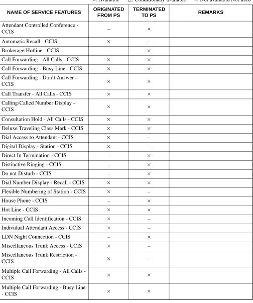
Table 1-11 List of CCIS Features
×: Available : Conditionally available –: Not available/Not used
NAME OF SERVICE FEATURES ORIGINATED FROM PS
TERMINATED
TO PS REMARKS
Attendant Controlled Conference -
CCIS – ×
Automatic Recall - CCIS × –
Brokerage Hotline - CCIS – ×
Call Forwarding - All Calls - CCIS × ×
Call Forwarding - Busy Line - CCIS × ×
Call Forwarding - Don’t Answer -
CCIS × ×
Call Transfer - All Calls - CCIS × ×
Calling/Called Number Display -
CCIS × ×
Consultation Hold - All Calls - CCIS × ×
Deluxe Traveling Class Mark - CCIS × ×
Dial Access to Attendant - CCIS × –
Digital Display - Station - CCIS × –
Direct In Termination - CCIS – ×
Distinctive Ringing - CCIS – ×
Do not Disturb - CCIS – ×
Dial Number Display - Recall - CCIS × ×
Flexible Numbering of Station - CCIS × –
House Phone - CCIS – ×
Hot Line - CCIS × ×
Incoming Call Identification - CCIS × –
Individual Attendant Access - CCIS × –
LDN Night Connection - CCIS – ×
Multiple Call Forwarding - Don’t
Answer - CCIS × ×
Night Connection - Fixed - CCIS – ×
Night Connection - Flexible - CCIS – ×
Off-Hook Queuing - CCIS × –
Single Digit Station Calling - CCIS × –
Station Controlled Conference - CCIS – ×
Step Call - CCIS – ×
Supervisory Call - CCIS – ×
Table 1-11 List of CCIS Features (Continued)
×: Available : Conditionally available –: Not available/Not used
NAME OF SERVICE FEATURES ORIGINATED FROM PS
TERMINATED
This chapter describes the installation for the Built-in PCS system.
1. INSTALLATION
This section explains how to connect the Built-in PCS system and its related equipment. Refer to the “Installation Manual” to learn the installation method of the PBX and its related equipment that is included here.
• ZT (Zone Transceiver) : Connection with S interface
• ZT (Zone Transceiver) : Connection with U interface
1.1 ZT (ZONE TRANSCEIVER) AND ITS CONNECTION WITH S INTERFACE 1. General
This part explains how to connect the Zone Transceiver (ZT).
2. Circuit Card
NAME OF CIRCUIT CARD 2W/4W REMARKS
PA-4CSIC 4W
3. Cable Connection
Figure 2-1 Related Equipment for Built-in PCS System (When using PA-4CSIC)
ATTENTION Contents Static Sensitive Handling Precautions Required PIM LT Back-board P Installation cable (SWVP50 lead) MDF No.1 No.3 No.0 26 27 28 29 30 31 32 33 34 35 36 37 38 39 40 41 42 43 44 45 46 47 48 49 50 1 2 3 4 5 6 7 8 9 10 11 12 13 14 15 16 17 18 19 20 21 22 23 24 25 No.0 No.1 No.2 No.3 RB0 TB0 RB1 TB1 RB2 TB2 RB3 TB3 RA0 TA0 RA1 TA1 RA2 TA2 RA3 TA3 TB RB TB RB TA RA Modular rosette (eg. RJ-45) Modular plug ZT
CSINT (LT cable) Champ connector lead
RA TA
MDF
ZT
Note: Confirm that the electric potential be-tween TA/TB and RA/RB (feed polari-ty) is normal before connecting ZT to modular rosette.
TA/TB minus RA/RB plus a. When using PA-4CSIC
Note 1: Maximum length of the cable to each ZT depends on the kind of cable (diameter) and the way of power supply (Power supply from Built-in PCS system/Local power supply).
Power supply from Built-in PCS system (Without arrestor, when feed output is 48V)
Local power supply
Note 2: Connection of the connector lead depends on the mounting location of CSINT circuit card. For more detail, refer to Chapter 3, "Circuit Cards".
Note 3: Below is the specification of modular plug that is used for the connection to ZT. • RJ-45 modular plug
Diameter 26 AWG 24 AWG 22 AWG 19 AWG
Distance (No arrestor)
762 m 1219 m 1676 m 2438 m
2500 ft 4000 ft 5500 ft 8000 ft
Diameter 26 AWG 24 AWG 22 AWG 19 AWG
Distance (No arrestor)
1189 m 1341 m 1676 m 2438 m
3900 ft 4400 ft 5500 ft 8000 ft
TERMINAL NUMBER
TERMINAL NUMBER
FUNCTION POLARITY
CSINT TERMINAL TERMINAL
EQUIPMENT CSINT SIGNAL FEED
1
2
a
b
Not used
Not used
Not used
Not used (8) (1)
Side view Front view
Figure 2-2 Related Equipment for Built-in PCS System (When using PA-4CSIE) ATTENTION Contents Static Sensitive Handling Precautions Required
a. When using PA-4CSIE
PIM Installation cable Back-board LT P MDF No.1 No.3 No.0 26 27 28 29 30 31 32 33 34 35 36 37 38 39 40 41 42 43 44 45 46 47 48 49 50 1 2 3 4 5 6 7 8 9 10 11 12 13 14 15 16 17 18 19 20 21 22 23 24 25 No.0 No.1 No.2 No.3 RB0 TB0 RB1 TB1 RB2 TB2 RB3 TB3 RA0 TA0 RA1 TA1 RA2 TA2 RA3 TA3 TB RB RA TA MDF ZT TB RB TA RA Modular rosette (eg. RJ-45) Modular plug ZT
Note: Confirm that the electric potential between TA/TB and RA/RB (feed polarity) is normal before connecting ZT to modular rosette.
TA/TB minus RA/RB plus
(Note 1)
Note 1: Maximum length of the cable to each ZT depends on the kind of cable (diameter) and the way of power supply (Power supply from Built-in PCS system/Local power supply).
Power supply from Built-In PCS system (Without arrestor)
Local power supply (Without arrestor)
Power supply (With arrestor)
Local power supply (With arrestor)
Note 2: Connection of the connector lead depends on the mounting location of CSINT circuit card. For more detail, refer to Chapter 3, "Circuit Cards".
Diameter 26 AWG(0.4Φ) 24 AWG(0.5Φ) 22 AWG(0.65Φ) 19 AWG(0.9Φ)
Distance 762 m 1219 m 1676 m 2438 m
2500 ft 4000 ft 5500 ft 8000 ft
Diameter 26 AWG(0.4Φ) 24 AWG(0.5Φ) 22 AWG(0.65Φ) 19 AWG(0.9Φ)
Distance 1189 m 1341 m 1676 m 2438 m
3900 ft 4400 ft 5500 ft 8000 ft
Diameter 26 AWG(0.4Φ) 24 AWG(0.5Φ) 22 AWG(0.65Φ) 19 AWG(0.9Φ)
Distance 300 m 500 m 800 m 1300 m
984 ft 1640 ft 2624 ft 4265 ft
Diameter 26 AWG(0.4Φ) 24 AWG(0.5Φ) 22 AWG(0.65Φ) 19 AWG(0.9Φ)
Distance 350 m 600 m 800 m 1300 m
1.2 ZT (ZONE TRANSCEIVER) AND ITS CONNECTION WITH U INTERFACE 1. General
This part explains how to connect the Zone Transceiver (ZT) when using the NT1.
2. Circuit Card
NAME OF CIRCUIT CARD 2W/4W REMARKS
PA-4CSID 2W
3. Cable Connection
ATTENTION Contents Static Sensitive Handling Precautions Required
PIM LT Back-board P
Installation cable (SWVP50 lead)
MDF
No.1
No.3 No.0
ZT DSU
Note 1: Maximum length of the cable to the DSU depends on the kind of cable (diameter) .
Note 2: Connection of the connector lead depends on the mounting location of CSINT circuit card. For more detail, refer to Chapter 3, "Circuit Cards".
Note 3: Maximum length of the cable to each ZT depends on the kind (diameter) of cable.
(Note 1)
1.3 BASIC KNOWLEDGE ON ZT INSTALLATION 1. Hypothetical Range of Radio Zone
When designing the image of a radio zone provided by a ZT, the radio zone can be drawn by using a specific prefixed distance characteristics value. Provided that a ZT is installed on a wall, the hypothetical distance characteristics range of the radio zone are as follows:
Indoor (General) : Radius of 49 ft (15 m) approximately Indoor (floor and corridor with unobstructed view): Radius of 65 ft (20 m) approximately
Outdoor: Radius of 164 to 196 ft (50 to 60 m) approximately
The range shown represent model values. Adjustment of the radio zone should be needed to design the final drawings as the radio wave fluctuates unpredictably. It is fundamental that each radio zone be assigned to ensure sufficient overlap as shown below.
Figure 2-3 Standard Installation Image
2. Image of ZT installation
Assuming a ZT is installed in a general office environment, one ZT can rarely cover the entire service area. So, a general service area is composed of multiple ZTs. The diagrams below show the image of ZT installation.
a. Single Floor Installation
ZTs are ideally installed at right angles or zigzag like spots on a dice.
b. Vertical Successive Floor Installation
It would be ideal to install ZTs at zigzag position alternately by even-number and odd-number floors so that transparent radio waves penetrating floors or ceilings are sufficient enough to receive electric field to be a radio zone and transparent radio wave between floors is sensed.
3. Radio Wave Propagation
Although radio waves used by the Built-in PCS System employ a digital signal of service frequency of approximately 1.9 GHz band, types of radio waves and types of propagation involved with basic radio wave propagation are considered to be the same as other analog radio waves.
• Types of radio waves
a. Direct waves: Radio waves that are propagated directly and linearly.
b. Reflected waves/ diffracted waves (indirect waves):
Radio waves that are propagated by being reflected or diffracted from an obstacle, such as a wall and ceiling.
c. Transmitted waves: Radio waves that travel through a wall, floor, partition, etc.
d. Propagating corridor waves:
Radio waves that travel along a corridor. (One type of reflected waves.)
e. Re-entering building waves:
Radio waves that go out of a building through a window, etc. and enter the building again.
FLOOR
CEILING
CEILING
WALL
WALL WALL
CORRIDOR
ANOTHER BUILDING
• Types of propagation
There are two major types of radio wave propagation: the line-of-sight propagation and the propagation beyond the horizon. As opposed to a cellular phone, consideration must be given to the line-of-sight propagation characteristics, where a ZT can be seen directly; as well as the propagation beyond the horizon, where radio waves travel through walls, ceilings, partition on the same floor, or another floor for a wireless system used on private premises with a very small service area.
Line-of-sight propagation
a. Free space propagation: • When a distance doubles, propagation loss increases by 6 dB.
• When a wavelength is halved, propagation loss increases by 6 dB.
Plane earth propagation: When a distance doubles,
propagation loss increases by 12 dB. (It is wavelength-independent.)
b. Propagation beyond the horizon
4. Installation of the ZT (Zone Transceiver)
Explained below is how to install the ZT and precautions to be made when mounting it.
a. The ZT is a communication device that sends a weak signal as radio waves, it should not be installed near and around equipment or an environment listed below to ensure the speech quality and various kinds of control operations – care must be taken.
[Indoor Installation]
Do not install around equipment capable of emitting noise (high frequency electric waves) such as wireless apparatus, television set, radio set, fluorescent lightening, and microwave oven.
[Outdoor Installation]
Avoid places easily affected by radio disturbances from cars, etc. (e.g., near a principal road). When installing by the sea, protect the ZT from salt using the outdoor mounting box and other protection if necessary.
Avoid places where there is a possibility to cause malfunction by radio waves.
When installing by the sea, protect the ZT from salt using the outdoor mounting box and other protection if necessary.
Besides, abnormal places with a fear of an explosion, subjected to malfunction by radio waves or to a strong electromagnetic field.
b. Avoid installing on a clay wall or plasterboard.
c. Ensure the wall or pillar to be used is strong enough to support the weight of the ZT, so that it does not shake, and has very little vibration.
d. If a possible installation wall contains reinforcing steel, etc., keep the antenna away from the wall by slightly tilting it.
2. INSTALLATION PROCEDURE OF ZONE TRANSCEIVER (ZT)
STEP 1: When mounting a ZT on a wall/ceiling, observe the following instructions.
i Do not mount a ZT on a wall/ceiling which cannot sustain the weight of ZT (e.g. a plaster wall, plywood wall).
ii Make a sufficient space so that the antenna can be placed at any angle.
iii When mounting a ZT on a wall which contains a reinforcing bar near the mounting location, place the antenna at an angle with the wall so as to make a space between the antenna and the reinforcing bar.
Figure 2-6 Example of Inappropriate Mounting
(i) (ii) (iii)
plaster wall
Re
in
fo
rc
in
g
B
a
STEP 2: Post the attached dimension drawing on the mounting location so as to mark the locations of screw holes. As shown Figure 2-7, two screw holes are provided as the lower mounting position. Depending on the mounting location, select either of the two mounting position.
Figure 2-7 Dimension Drawing for ZT Installation (1/2)
STEP 3: Secure the furnished screws to the marked locations. In this instance, for the lower mounting screw hole select either of mounting options depending on the mounting location.
Leave a space [more than 4.3 in (110 (mm)] for the antenna.
4.
2
(
1
07
)
Screw of the mounting tag
Screw of ZT
4.9 (1 24.4)
Mounting tag ZT
1.6 (40 )
6.3 (1 60)
5.
4
(
1
38
)
3.
2
(
8
0)
4.
0 (
1
0
0
)
Figure 2-8 Dimension Drawing for ZT Installation (2/2)
0.2 (5) 0.5 (12)
2.4 (60) 0.08 (2)
0.3 (8)
0.
2
(
5
)
Front
0.9 (22.5)
4.9 (124.4)
2
.2
(5
4)
0.
5
(
1
3.
5)
0.
4
(
1
0)
3.
1 (
7
8
.75
)
0.
8 (
2
1
)
0.08 (2) 0.3 (8)
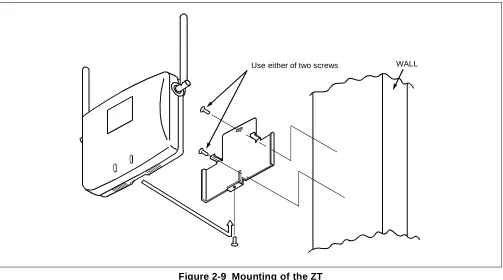
STEP 4: Mount the ZT on the wall and slide it so that the heads of screws may fix the ZT tightly.
Figure 2-9 Mounting of the ZT
STEP 5: If power feeding from the PCS is impossible, use the “AC adapter” for local power feeding. The “AC adapter” is connected to the ZT as shown below.
Figure 2-10 Local Power Feeding
Use either of two screws WALL
Screw
Connector cover Rear
Modular jack
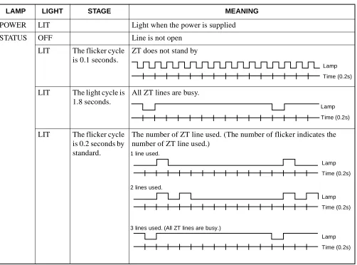
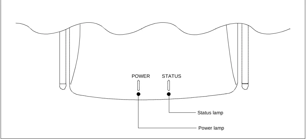
STEP 6: Turn ON the power to the ZT to confirm the lamp indications are normal. Refer to Table 2-1 and Figure 2-11.
* One cycle is 2 second
Table 2-1 Meaning of LED Indications
LAMP LIGHT STAGE MEANING
POWER LIT Light when the power is supplied
STATUS OFF Line is not open
LIT The flicker cycle is 0.1 seconds.
ZT does not stand by
LIT The light cycle is 1.8 seconds.
All ZT lines are busy.
LIT The flicker cycle is 0.2 seconds by standard.
The number of ZT line used. (The number of flicker indicates the number of ZT line used.)
Lamp Time (0.2s)
Lamp Time (0.2s)
Lamp Time (0.2s)
Lamp Time (0.2s) Lamp 1 line used.
2 lines used.
3 lines used. (All ZT lines are busy.)
Figure 2-11 LEDs on the Zone Transceiver
POWER STATUS
STEP 7: The angle of the antenna is variable between 0º and 180º as shown below. In a wall-mount installation, normally the antenna is set at an angle of 0º so that the antenna may be vertical with the radio zone.
Note: Since the antenna is easily broken, handle it with care.
Figure 2-12 Adjustment of Antenna
90 90
3. SYSTEM START-UP
After finishing the installation of the PBX (installation of the PBX, confirmation of the switch-setting of every circuit card and cable connection), start up the system. This diagram outlines the procedure to start up the system. For more details, refer to the “Installation Manual.”
START
Insulation test
Heat-run
Power on
Program Install
Program load
Assignment of Office Data
Office Data Back-up
Confirmation of Lamp, display and System message
Initialization
This chapter describes the circuit cards related to the Built-in PCS system.
Refer to the “Circuit Card Manual” to check other circuit cards that are introduced here.
• PA-4CSIC (CSINT) : ZT (Zone Transceiver) Interface Note 1
• PA-4CSID (CSINT) : ZT (Zone Transceiver) Interface Note 2
• PA-4CSIE (CSINT) : ZT (Zone Transceiver) Interface Note 1
• PA-4CSIF (CSINT) : ZT (Zone Transceiver) Interface Note 2
• PA-CK16 (WCS) : Synchronous Signal Transmission Circuit for CS/ZT
PA-4CSIC (CSINT) : ZT (Zone Transceiver) Interface
1. General Functions
This circuit card is designed to provide the ISDN S interface to the Zone Transceiver (ZT).
Specifications and functions of this circuit card are shown below.
• A maximum of four ZTs can be accommodated in one 4CSIC circuit card.
• Interface with ZTs is based on the ISDN standard interface, though the multi-point connection of the ZTs is not available.
• I.430, Q.921 Interface
[Each B Channel of 32 kbps in the 2B+D (B=64 kbps) can be used as two channels.] • Feed functions to ZT: 48 Vtyp, maximum of 250 mA, feed polarity: reverse
• Equipped with 32k ADPCM (TSW: 64 kbps, ZT: 32 kbps) • Burst synchronization function of 5 ms (multi-frame) to ZT • Provided with 16 channels of PB (DTMF) sender
Figure 3-1 Location of Card in System 2. Mounting Location of Circuit Card and Its Conditions
• Mounting location of circuit card: Universal slot of the PIM Conditions: 12 CSINT circuit cards can be mounted in one PIM.
ZT PS
PS
TSW
PLO PA-4CSIC
Equivalent to I.430
3. Lamp, Key, Connector and Their Location
The following diagram shows the location of Lamp, Key and Connectors.
Figure 3-2 Lamp, Key and Connectors : PA-4CSIC
OPE
MB
SW10
NOPE
MODE SWL3 SWL2 SWL1 SWL0
L3 L2 L1 L0 BL34 BL33 BL32 BL31 LYR3 PWR3 BL24
BL23 BL22 BL21 LYR2 PWR2 BL14 BL13 BL12 BL11 LYR1 PWR1
SYNC BL04 BL03 BL02 BL01 LYR0 PWR0
4. Lamp Indication
Shown below are the contents of lamp indication on this circuit card.
n=0~3
Note 1: B1 through B4 channels represent channel names of 32k ADPCM.
LAMP NAME COLOR MEANING
OPE Green Remains lit when this card is operating normally.
NOPE Red Remains lit when this card is in make-busy state.
BLn4 Green Remains lit when B4 channel of the line #n is communicating Note 1
Flashing Flashes while the corresponding circuit is in make-busy state (60 IPM).
OFF Remains off when the corresponding circuit is idle.
BLn3 Green Remains lit when B3 channel of the line #n is communicating Note 1
Flashing Flashes while the corresponding circuit is in make-busy state (60 IPM).
OFF Remains off when the corresponding circuit is idle.
BLn2 Green Remains lit when B2 channel of line #n is communicating Note 1
Flashing Flashes while the corresponding circuit is in make-busy state (60 IPM).
OFF Remains off when the corresponding circuit is idle.
BLn1 Green Remains lit when B1 channel of the line #n is communicating Note 1
Flashing Flashes while the corresponding circuit is in make-busy state (60 IPM).
OFF Remains off when the corresponding circuit is idle.
LYRn Green Remains lit when the layer 2 link of line #n is established
Flashing Flashes when layer 1 of the line #n is synchronized (120 IPM).
OFF Layer 1 and Layer 2 have not been established.
PWRn Red Lights when the power supply of the line #n fails.
5. Switch Settings
Standard settings of switches on this circuit card are shown in the table below.
SWITCH NAME SWITCH NUMBER
SWITCH SETTING
STANDARD
SETTING MEANING
MB
(Toggle Switch)
Up Circuit card make-busy set
Down
Circuit card make-busy cancel
MBR
(Piano-Key Switch)
0 ON Line 0 make-busy request
OFF × Line 0 make-busy request cancel
1 ON Line 1 make-busy request
OFF × Line 1 make-busy request cancel
2 ON Line 2 make-busy request
OFF × Line 2 make-busy request cancel
3 ON Line 3 make-busy request
OFF × Line 3 make-busy request cancel
MODE
(Rotary Switch)
0 Echo Canceller is not effective
1 Not used
2 Echo Canceller is effective
3~F Not used
SW10
(DIP Switch)
1 OFF × Fixed
2 ON × Fixed
3 ON × Fixed
4 ON × Fixed
ON (MB) OFF
No. 3 No. 2 No. 1 No. 0 OFF
ON
ON
SWITCH NAME SWITCH NUMBER
SWITCH SETTING
STANDARD
SETTING MEANING
SW11
1
PAD on TSW side
2
3
PAD on LINE side
4
5
PB Sender Mode (Law/Level) Selection
Note: µ/A-law can be selected on the TSW side PAD. µ-law Standard =High: -7.0 dBm
Low: -9.0 dBm A-law Standard =High: -8.0 dBm
Low: -10.0 dBm 6
7 ON × Fixed
8 ON × Fixed
(DIP Switch) ON
1 2 3 4 5 6 7 8 SWITCH 1 SWITCH 2 PAD
OFF OFF Not used
ON OFF A-Law
OFF ON µ (PS)-A (TSW) Conversion
ON ON µ-Law (Standard Setting)
SWITCH 3 SWITCH 4 PAD
OFF OFF Not used
ON OFF A-Law
OFF ON µ (PS)-A (TSW) Conversion
ON ON µ-Law (Standard Setting)
SWITCH 5 SWITCH 6 LAW/LEVEL
OFF OFF Not used
ON OFF
OFF ON
ON ON µ-law Standard
Note 1: The following diagram shows the PAD control method. [Firmware: SW-329]
SWITCH NAME SWITCH NUMBER
SWITCH SETTING
STANDARD
SETTING MEANING
SW12
(DIP Switch)
1~3
PAD control (PAD value of the TSW side) Note 1
4~6
PAD control (PAD value of the line side) Note 1
7 OFF × Fixed
8 OFF × Fixed
ON
1 2 3 4 5 6 7 8 SWITCH 1 SWITCH 2 SWITCH 3 PAD VALUE OF THE TSW SIDE
OFF OFF OFF Not used
ON OFF OFF PAD 2=0 dB, PAD 1=–5 dB
OFF ON OFF PAD 2=0 dB, PAD 1=–3 dB
ON ON OFF PAD 2=0 dB, PAD 1=0 dB
OFF OFF ON Not used
ON OFF ON PAD 2=0 dB, PAD 1=5 dB
(Standard setting)
OFF ON ON PAD 2=0 dB, PAD 1=3 dB
ON ON ON PAD 2=0 dB, PAD 1=0 dB
SWITCH 4 SWITCH 5 SWITCH 6 PAD VALUE OF THE LINE SIDE
OFF OFF OFF Not used
ON OFF OFF PAD 4=0 dB, PAD 3=–5 dB
OFF ON OFF PAD 4=0 dB, PAD 3=–3 dB
ON ON OFF PAD 4=0 dB, PAD 3=0 dB
OFF OFF ON Not used
ON OFF ON PAD 4=0 dB, PAD 3=5 dB
OFF ON ON PAD 4=0 dB, PAD 3=3 dB
ON ON ON PAD 4=0 dB, PAD 3=0 dB
(Standard setting)
Echo Canceller (If MODE=0)