Installation Instructions and
Release Notes for Versions 1.08,
1.08.02, and 1.20
This manual has been developed by Nitsuko America. It is intended for the use of its customers and service personnel, and should be read in its entirety before attempting to install or program the system. Any comments or suggestions for improving this manual would be appreciated. Forward your remarks to:
Nitsuko America, Telecom Division 4 Forest Parkway
Shelton, CT 06484
Attention: Manager, Technical Publications
Nothing contained in this manual shall be deemed to be, and this manual does not constitute, a warranty of, or representation with respect to, any of the equipment covered. This manual is subject to change without notice and Nitsuko America has no obligation to provide any updates or corrections to this manual. Further, Nitsuko America also reserves the right, without prior notice, to make changes in equipment design or components as it deems appropriate. No representation is made that this manual is complete or accurate in all respects and Nitsuko America shall not be liable for any errors or omissions. In no event shall Nitsuko America be liable for any incidental or consequential damages in connection with the use of this manual. This document contains proprietary information that is protected by copyright. All rights are reserved. No part of this document may be photocopied or reproduced without prior written consent of Nitsuko America.
©2000 by Nitsuko America. All Rights Reserved
About NVM-2e... 1
About This Supplement... 2
Installation Instructions... 3
Voice Mail Specifications ... 7
Site Requirements... 7
Install NVM-2e... 8
Connect a Laptop to the NVM-2e... 9
Connect a Phone System to NVM-2e ... 11
Program NVM-2e for the Correct Phone System... 14
Program Your Phone System for Voice Mail... 14
Program NVM-2e ... 14
Start Up the System Configuration Management Program:... 15
Release Notes for Software Version 1.08... 17
Version 1.08 Feature Availability... 21
Changes and Additions in the System Configuration Management Program ... 21
Changing Ranges of Mailboxes in the Numbering Plan ... 21
Port Options for Lamping and Message Notification... 25
System Options ... 27
¾ Lamp On string ... 28
¾ Lamp Off string ... 28
¾ Silence limit during recording (secs) ... 29
¾ Eliminate silence during recording? ... 29
Channel Parameters... 30
¾ DTMF detection time (10 ms) during playback - Default is 5 ... 31
¾ DTMF detection time (10 ms) during record - Default is 6... 31
Call Processing Parameters ... 32
¾ CmdInputTimeout (sec) Time limit for dialing commands (for call routing)... 34
¾ DtmfTimeout (sec) time allowed user between dialing digits (for call routing) ... 34
¾ NoAnswerRings Number of ringback seconds before regarding call not answered... 35
¾ NormalGain Default volume setting for recorded messages (Min: -10 Max: 10) ... 35
¾ PromptAtten Volume setting for Voice Prompts (Min: -10 Max: 10) ... 35
Changes in Drive Letters Displayed... 36
Actions Added to the Dial Action Table (CR,27 and HU, 48) ... 36
Immediate Recording of Message for Subscriber ... 36
Pressing SA or E While Listening to Messages ... 36
Message Notification... 37
Release Notes for Software Version 1.08.02... 39
Version 1.08.02 Feature Availability... 43
Changes and Additions in the System Configuration Management Program ... 43
Dial Strings... 43
Revisions to the Names of Various Parameters ... 43
Release Notes for Software Version 1.20... 45
Version 1.20 Feature Availability... 49
Table of Contents
ii Issue 1-0
Expanded Phone System Compatibility ... 49
Changes and Additions in the System Configuration Management Program ... 50
System Options ... 50
¾ Flash timer ... 50
¾ Wait after last protocol digit (0-99 sec) ... 50
¾ Operator’s extension number (2 to 7 digits, N-None) ... 50
¾ Temporarily disable the system administrator password ... 50
Global Parameters... 50
¾ s_bnc(10ms)minimum duration of silence to detect change... 50
Call Processing Parameters ... 51
¾ ReadyToneStr... 51
¾ ReadyToneTimeout ... 51
¾ ReadyToneDuration minimum length of ready tone ... 51
¾ ConversationLength (sec) time allowed for record coversation function ... 52
¾ SoundCutoff ... 52
¾ DTMFCutoff ... 52
Changed Format for the Tone Table... 53
English Prompt Set and Voice Coder... 53
Appendix A ... 54
User’s Menu... 54
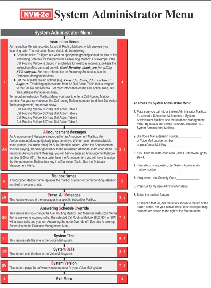
System Administrator Menu... 55
About NVM-2e
Your NVM-2e generally operates and is programmed as described in the NVM-2 Setup Guide (P/N 17690SET02 or higher), NVM-2 Programming Guide (P/N 17690INS02 or higher) and NVM-2 Release Notes for Version 1.05.07 (P/N 17690UPG01 or higher).
The NVM-2e cabinet is different from the NVM-2. (The NVM-2 is the unit shown in the documentation mentioned above.) See Figures 1 and 2 for different views of the NVM-2e.
NVM-2e is flash-RAM based. Batteries are not required to back up system memory.
Note: You should ignore the battery installation instructions in the NVM-2 documentation.
NVM-2e is available as a 2 port, 3 hour unit (P/N 17780-2P) or as a 4 port, 3 hour unit (P/N 17780-4P). NVM-2e has all of the features of an NVM-2 as well as all of the changes and enhancements described in this supplement.
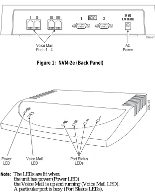
Figure 1: NVM-2e (Back Panel)
Note: The LEDs are lit when:
the unit has power (Power LED)
the Voice Mail is up and running (Voice Mail LED). A particular port is busy (Port Status LEDs).
NVM-2ex Installation Instructions and Software Release Notes
2 Issue 1-0
About This Supplement
This supplement is divided into two sections: Installation Instructions and Software Release Notes.
The Installation Instructions tell you how to install the NVM-2e. The Software Release Notes describe any new or enhanced features that are available in software release 1.08, 1.08.02 and 1.10
Voice Mail Specifications ... 7
Site Requirements... 7
Install NVM-2e... 8
Connect a Laptop to the NVM-2e... 9
Connect a Phone System to NVM-2e ... 11
Program NVM-2e for the Correct Phone System... 14
Program Your Phone System for Voice Mail... 14
Program NVM-2e ... 14
Voice Mail Specifications
Number of Ports: 2 or 4
Voice Storage Capacity: 3 hours
Subscriber Mailboxes: Up to 50 Subscriber Mailboxes
Trunk Mailboxes Up to 8, depending on phone
system
Telephone System A Phone System Single Line
Programming Interface: Extension
Electrical Requirements: 120V, 60 Hz
Environmental Requirements: 50-104 deg F, 10-40 deg C
Site Requirements
„ Do not expose this product to rain or any type of moisture.
„ Do not locate the unit near heating appliances.
„ Do not expose the unit to direct sunlight.
„ Locate the unit away from devices that generate electrical noise
like fluorescent lamps and motors.
„ Protect the unit from dust, high temperatures, and vibration.
„ Do not place any covering over the unit while it is in operation.
„ Do not obstruct the ventilation holes on the sides of the unit.
„ Allow at least two inches of clearance from any adjacent surface.
„ Keep the environment at a temperature of 50 to 104 deg F (10 to
NVM-2e Installation Instructions
8 Issue 1-0
Install NVM-2e
Use the following instructions to install your NVM-2e.
To Install the NVM-2e:
1. Place the Voice Mail on any sturdy flat surface.
OR
Mount the Voice Mail on a wall, using the screw slots located on the bottom of the cabinet. Make sure that the ventilation slots are not blocked. Position the cabinet so that the LEDs can be seen.
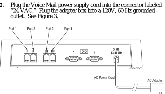
2. Plug the Voice Mail power supply cord into the connector labeled
“24 VAC.” Plug the adapter box into a 120V, 60 Hz grounded outlet. See Figure 3.
1 IOIOI 2 0.7A 50-60Hz24 VAC
NVM2exVB-C1
Port 2 Port 4 Port 1 Port 3
AC Adapter AC Power Cord
Note: Your unit may have only two ports available.
Connect a Laptop to the NVM-2e
A laptop is required for certain programming and is also used as a tool for diagnostics.
You will need to connect a laptop computer to NVM-2e so that you can access a program called “The System Configuration Management Program.” This program allows you to configure certain parameters in the Voice Mail which you cannot access through a System
Administrator’s Mailbox.
The System Configuration Management Program is described in detail in the NVM-2 Release Notes for Version 1.05.07 (P/N 17690UPG01 or higher) and in this supplement beginning on page 17.
Connecting a laptop to the NVM-2e is different than as described in the Release Notes for an NVM-2. Use the following instructions to connect a laptop to the NVM-2e.
To connect a laptop to NVM-2e:
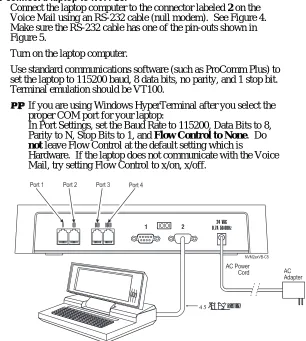
1. Connect the laptop computer to the connector labeled 2 on the
Voice Mail using an RS-232 cable (null modem). See Figure 4. Make sure the RS-232 cable has one of the pin-outs shown in Figure 5.
2. Turn on the laptop computer.
3. Use standard communications software (such as ProComm Plus) to
set the laptop to 115200 baud, 8 data bits, no parity, and 1 stop bit. Terminal emulation should be VT100.
• If you are using Windows HyperTerminal after you select the
proper COM port for your laptop:
In Port Settings, set the Baud Rate to 115200, Data Bits to 8, Parity to N, Stop Bits to 1, and Flow Control to None. Do
not leave Flow Control at the default setting which is
Hardware. If the laptop does not communicate with the Voice Mail, try setting Flow Control to x/on, x/off.
1 IOIOI 2 0.7A 50-60Hz24 VAC
NVM2exVB-C5
AC Adapter AC Power
Cord Port 2 Port 4
Port 1 Port 3
RS-232 Cable
NVM-2e Installation Instructions
10 Issue 1-0
Connect a Laptop to the NVM-2e (cont’d)
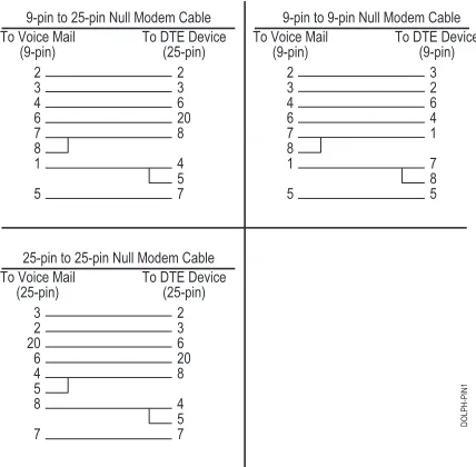
Figure 5: Required Pin-outs for the RS-232 Cable
4. When the laptop is communicating with the Voice Mail, you will
see a menu screen and the prompt, Main Menu - > .
Connect a Phone System to NVM-2e
You can connect a Portrait, 28i, 124i, Onyx VS or Businesscom DS01 phone system to the NVM-2e. For specific equipment that you need for each phone system, see the NVM-2 Setup Guide (P/N 17690SET02 or higher).
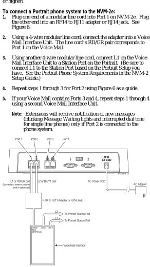
To connect a Portrait phone system to the NVM-2e:
1. Plug one end of a modular line cord into Port 1 on NVM-2e. Plug
the other end into an RF14 to RJ11 adapter or RJ14 jack. See Figure 6.
2. Using a 4-wire modular line cord, connect the adapter into a Voice
Mail Interface Unit. The line cord’s RD/GR pair corresponds to Port 1 on the Voice Mail.
3. Using another 4-wire modular line cord, connect L1 on the Voice
Mail Interface Unit to a Station Port on the Portrait. (Be sure to connect L1 to the Station Port based on the Portrait Setup you have. See the Portrait Phone System Requirements in the NVM-2 Setup Guide.)
4. Repeat steps 1 through 3 for Port 2 using Figure 6 as a guide.
5. If your Voice Mail contains Ports 3 and 4, repeat steps 1 through 4
using a second Voice Mail Interface Unit.
Note: Extensions will receive notification of new messages (blinking Message Waiting lights and interrupted dial tone for single line phones) only if Port 2 is connected to the phone system.
1 IOIOI 2 0.7A 50-60Hz24 VAC
NVM2exVB-C4
AC Adapter AC Power Cord
Port 2 Port 4 Port 1 Port 3
RJ14 to RJ11 Adapter or RJ14 Jack
To Portrait Station Port L1
L2
To Portrait Station Port
Voice Mail Interface VOICE
MAIL INTERFACE
LINE 2 LINE 1 L2 or BK/Y1 pair L1 or RD/GR pair
(connects to lower-numbered
port in connector)
NVM-2e Installation Instructions
12 Issue 1-0
Connect a Phone System to NVM-2e (cont’d)
Note: An alternate method for installing the 28i/124i is on the following page.
To connect NVM-2e to a 28i, 124i, Onyx VS or Businesscom DS01
phone system:
1. Plug one end of a modular line cord into Port 1 on the NVM-2e.
Plug the other end into an ASI or Dual ASI.
2. Connect the ASI or Dual ASI to the phone system. Figure 7 shows
connecting to a Dual ASI.
3. Repeat steps 1 and 2 for Port 2.
4. Repeat steps 1 and 2 for Ports 3 and 4 if your Voice Mail contains
four ports.
Note: Extensions will receive notification of new messages (blinking Message Waiting lights and interrupted dial tone for single line phones) only if Port 2 is connected to the phone system.
1 IOIOI 2 0.7A 50-60Hz24 VAC
NVM2exVB-C3
AC Adapter AC Power Cord
Port 2 Port 4 Port 1 Port 3
Dual ASI
To Phone System
Connect a Phone System to NVM-2e (cont’d)
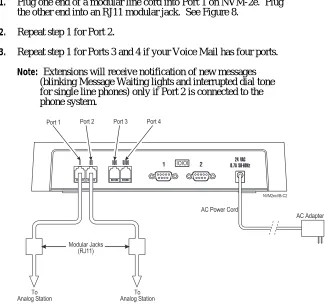
Note: The following is an alternate method for connecting the 28i or 124i to the Voice Mail.
To connect NVM-2e to a 28i or 124i Phone System:
1. Plug one end of a modular line cord into Port 1 on NVM-2e. Plug
the other end into an RJ11 modular jack. See Figure 8.
2. Repeat step 1 for Port 2.
3. Repeat step 1 for Ports 3 and 4 if your Voice Mail has four ports.
Note: Extensions will receive notification of new messages (blinking Message Waiting lights and interrupted dial tone for single line phones) only if Port 2 is connected to the phone system.
1 IOIOI 2 0.7A 50-60Hz24 VAC
NVM2exVB-C2
AC Adapter AC Power Cord
Port 2 Port 4 Port 1 Port 3
Modular Jacks (RJ11)
To Analog Station To
Analog Station
NVM-2e Installation Instructions
14 Issue 1-0
Program NVM-2e for the Correct Phone System
The default phone system that the Voice Mail recognizes as installed is the Portrait. If you connected a 28i, 124i, Onyx VS or Businesscom DS01 to NVM-2e, you will need to change the default setup in programming so that the Voice Mail recognizes your phone system.
To change the phone system that NVM-2e recognizes as installed:
1. Log onto the System Administrator Mailbox (extension 10 in the
Portrait). From any extension:
• Get intercom dial tone.
• Dial NVM-2e Master Number.
• Dial 9*.
• Wait for Main Greeting, then press #.
• When you are requested to enter a mailbox number, dial 10.
2. At the Main Menu, press DM for the Database Management Menu.
3. Press SI for System Initialization.
4. Press 3 to initialize the Voice Mail database for a particular phone system.
5. Enter the code for the phone system you installed. Valid codes are
listed below: 1 - Portrait 2 - 28i/124i
3 - Onyx VS or Businesscom DS01
4 - DS-2000 (available in software version 1.10)
6. Press #. Follow the voice prompts.
Program Your Phone System for Voice Mail
Certain programs in your phone system require specific entries when you integrate with NVM-2e. See the NVM-2 Setup Guide (P/N 17690SET02 or higher) for specific programs that you need to set up in your phone system so that it integrates with the Voice Mail.
Program NVM-2e
Follow the instructions in the NVM-2 Programming Guide (P/N 17690INS02 or higher) and NVM-2 Release Notes for Version 1.05.07 (P/N 17690UPG01 or higher) to customize your NVM-2e. However
before you program the NVM-2e, be sure to read the information in the Release Notes portion of this supplement.
The Release Notes section provides information about the new and enhanced features that are available on the NVM-2e. This information
Start Up the System Configuration Management Program:
The System Configuration Management Program allows you to configure certain parameters in the Voice Mail which you cannot access through a System Administrator’s Mailbox.
The System Configuration Management Program is described in detail in the NVM-2 Release Notes for Version 1.05.07 (P/N 17690UPG01 or higher).
To use The System Configuration Management Program, you need to connect a laptop computer to the NVM-2e as explained on page 9.
To start up The System Configuration Management Program:
1. Connect a laptop to the Voice Mail. For instructions, see page 9.2. At the prompt, Main Menu - > type exit and press <Enter>. You will exit the Voice Mail System and go to DOS.
3. At the DOS prompt, type sysedit and press <Enter>.
The System Configuration Management Program Main Menu appears and lists the phone system that you have installed with the Voice Mail System. For example:
Selected system Type: PORTRAIT
Enter To view / modify O ... system Options R …poRt Options G ... Global parameters C ... Channel parameters P ... call Processing parameters T ... Tone table
M …Mailbox Range Q ... Quit
>:
See Part II: The System Configuration Management Program in the NVM-2 Release Notes (P/N 17690UPG01 or higher) for more information on this program and the Release Notes in this supplement (beginning on page 17).
Note: The Learn Tone Procedure described in the NVM-2 Release Notes (P/N 17690UPG01 or higher) is not currently available on the NVM-2e.
To exit the System Configuration Management Program:
1. From the System Configuration Management Program Main Menu
(see above), enter Q and press <Enter>.
2. You return to the DOS prompt.
Release Notes for
Version 1.08
New and Enhanced
Version 1.08 Feature Availability... 21 Changes and Additions in the System Configuration Management Program ... 21 Changing Ranges of Mailboxes in the Numbering Plan ... 21 Port Options for Lamping and Message Notification... 25 System Options ... 27
¾ Lamp On string ... 28
¾ Lamp Off string ... 28
¾ Silence limit during recording (secs) ... 29
¾ Eliminate silence during recording? ... 29 Channel Parameters... 30
¾ DTMF detection time (10 ms) during playback - Default is 5 ... 31
¾ DTMF detection time (10 ms) during record - Default is 6... 31 Call Processing Parameters ... 32
¾ CmdInputTimeout (sec) Time limit for dialing commands (for call routing)... 34
¾ DtmfTimeout (sec) time allowed user between dialing digits
(for call routing) ... 34
¾ NoAnswerRings Number of ringback seconds before regarding call not answered... 35
¾ NormalGain Default volume setting for recorded messages (Min: -10 Max: 10) ... 35
Version 1.08 Feature Availability
This section of the supplement describes the new and enhanced features available with Software Version 1.08.
Changes and Additions in the System Configuration Management
Program
The System Configuration Management Program in the NVM-2e has several changes and additions from the program described in the NVM-2 documentation. These changes and additions are described on the following pages.
For information on starting up this program, see page 15 in this supplement. See Part II: The System Configuration Management
Program in the NVM-2 Release Notes (P/N 17690UPG01 or higher)
for more information.
Changing Ranges of Mailboxes in the Numbering Plan
(New for the NVM-2e)
When you select a phone system for integration, the Voice Mail automatically assigns numbers to Subscriber Mailboxes. Generally, these numbers start at the lowest numbered extension and continue in sequence until the total number of Subscriber Mailboxes reaches 50.
However, some phone systems have fewer than 50 extensions. For these systems, the Voice Mail provides Subscriber Mailbox numbers that correspond to the current phone system numbering plan. Since the total number of Subscriber Mailboxes in the Voice Mail always equals 50, the remaining mailboxes should be equal to the differences between 50 and the actual number of extensions in your system. In most cases, these mailboxes are placed in the 800 range, starting with extension 810.
You can modify the default numbering plan by changing the range of numbers for your Subscriber Mailboxes. For example, the default numbering for Subscriber Mailboxes in the Onyx VS phone system is 300 to 347 and 810, 811. You can change this numbering plan if you want your mailboxes to be numbered differently.
To create or change the mailbox ranges, you use the System Configuration Management Program, which is a program in the Voice Mail. To access this program, you need a laptop computer connected to the Voice Mail. For instructions on accessing the System Configuration Management Program, see page 15. For additional information on using the System Configuration Management Program, see Part II: The System Configuration Management Program in the NVM-2 Release Notes (P/N 17690UPG01 or higher).
Release Notes for Software Version 1.08
22 Issue 1-0
Changes and Additions in the System Configuration Management
Program (cont’d)
Changing Ranges of Mailboxes in the Numbering Plan (cont’d)
IMPORTANT
You need to set up all your ranges before you perform any other Voice Mail programming. If you add a mailbox range at a later date, you will have to re-initialize the Voice mail System. After the re-initialization, you must re-program the entire system, and users must re-record their personal Mailbox Greetings.
The following table shows the default numbering of the Subscriber Mailboxes for each phone system. It is recommended that you do not change the first Trunk Mailbox number, unless the trunks in your phone system start with a different number.
Phone System Default
Subscriber Mailbox Numbering
Default First Trunk Mailbox Number
Portrait 308/824 10-59 01
28i/124i 301-359 001
Onyx VS 300-347, 810-811 348
To change the mailbox range:
1. Connect a laptop to the Voice Mail. For instructions, see page 9. Start up the System Configuration Management Program. For instructions, see page 15.
The Main Menu will appear for your phone system. The following is an example of the Main Menu:
Selected system Type: XX
Enter To view / modify O ... system Options R …poRt Options G ... Global parameters C ... Channel parameters P ... call Processing parameters T ... Tone table
M …Mailbox Range Q ... Quit
>:
Changes and Additions in the System Configuration Management
Program (cont’d)
Changing Ranges of Mailboxes in the Numbering Plan (cont’d)
You will see the table for setting up Mailbox Ranges. For example:
Mailbox Ranges for XX
Seq. Starting Mailbox Mailbox
# Mailbox # Count Type
1 ... ... 0 ... Undef
2 ... ... 0 ... Undef 3 ... ... 0 ... Undef 4 ... ... 0 ... Undef 5 ... ... 0 ... Undef 6 ... ... 0 ... Undef 7 ... ... 0 ... Undef 8 ... ... 0 ... Undef 9 ... ... 0 ... Undef 10 ... ... 0 ... Undef
P ... Print/display the mailbox range table
E ... Edit a mailbox range by sequence # C ... Clear a mailbox range by sequence # Q ... Quit and return to main menu
3. Enter E to edit the mailbox range and press <Enter>.
4. At the prompt, Enter the sequence number >:, enter an available sequence number (e.g., 1), and press <Enter>.
5. At the prompt, Starting mailbox number (2 to 7 digits), enter the
number you want as the first mailbox in your numbering plan. This number may be from two to seven digits in length. Be sure to enter the number exactly as it will be dialed. Press <Enter>.
6. Enter the number of mailboxes that will be in this range at the
Number of consecutive mailboxes: prompt, and press <Enter>.
You will see:
Mailbox type: U-Undefined E-Extension T-Trunk
7. Enter the letter corresponding to the type of mailbox you want to
assign to the range. Press <Enter>. You should only assign Trunk Mailboxes if your phone system sends trunk ID information (and you could not disable the phone system from sending it). The phone system uses Trunk Mailboxes for this information. You cannot program any parameters for Trunk Mailboxes.
8. Repeat steps 3 through 7 for each range of consecutive mailboxes
in your numbering plan.
Notes: The total number of extensions (Subscriber Mailboxes) is 50. As a result, the total number of mailboxes when the ranges are added together must not exceed 50.
You can have up to eight trunk mailboxes.
If you want to change system numbering plan, be sure you do so before you perform any other programming.
Release Notes for Software Version 1.08
24 Issue 1-0
Changes and Additions in the System Configuration Management
Program (cont’d)
Changing Ranges of Mailboxes in the Numbering Plan (cont’d)
9. When finished, press Q and then press <Enter>.
10. At the System Configuration Main Menu, press Q then <Enter>.
11. At the DOS prompt, type VM and press <Enter> to start up the Voice Mail.
12. Logon to a System Administrator’s Mailbox, and re-initialize the
Voice Mail Database.
For instructions, see the NVM-2 Programming Guide, Chapter 5.
Example: A sample Mailbox Range Table is shown below Mailbox Ranges for XX
Seq. Starting Mailbox Mailbox
# Mailbox # Count Type
1 ... 10 ... 6 ... Extension
2 ... 20 ... 6 ... Extension 3 ... 30 ... 6 ... Extension 4 ... 71 ... 2 ... Trunk 5 ... ... 0 ... Undef 6 ... ... 0 ... Undef 7 ... ... 0 ... Undef 8 ... ... 0 ... Undef 9 ... ... 0 ... Undef 10 ... ... 0 ... Undef
P ... Print/display the mailbox range table
E ... Edit a mailbox range by sequence # C ... Clear a mailbox range by sequence # Q ... Quit and return to main menu
Explanation:
In this example, the Mailbox/Extension Range consists of 4 sequences. Each sequence is numbered consecutively and contains the following entries:
• Sequence 1 (10 through 15)
A 10 is entered for the Starting Mailbox #. Since there are a total of 6 mailboxes in this sequence, a 6 is entered for the Mailbox
Count. Because they are all Subscriber Mailboxes, the entry is
Extension for the Mailbox Type.
• Sequence 2 (20 through 25)
A 20 is entered as the Starting Mailbox #. Since there are a total of 6 mailboxes in this sequence, a 6 is entered for the Mailbox
Count. Because they are all Subscriber Mailboxes, the entry is
Extension for the Mailbox Type.
• Sequence 3 (30 through 35)
A 30 is entered for the Starting Mailbox #. Since there are a total of 6 mailboxes in this sequence, a 6 is entered for the Mailbox
Count. Because they are all Subscriber Mailboxes, the entry is
Extension for the Mailbox Type.
• Sequence 4 (71 and 72)
A 71 is entered for the Starting Mailbox #. Since there are only two mailboxes in this sequence, a 2 is entered for the Mailbox
Count. Because they are both Trunk Mailboxes, the entry is
Changes and Additions in the System Configuration Management
Program (cont’d)
Port Options for Lamping and Message Notification
The System Configuration Management Program provides you with the ability to change the Voice Mail ports that allow or do not allow Lamping callouts and Message Notification callouts.
You can enable (allow) either or both features on one, some, or all Voice Mail ports. The Voice Mail will then use a port you enabled to inform Subscribers that they received new messages. How the Voice Mail informs a Subscriber with a new message depends on the feature or features enabled:
„ When Lamping is enabled, the Voice Mail will inform the
Subscriber by turning on the Msg Waiting Lamp at the Subscriber’s extension.
„ When Message Notification is enabled, the Voice Mail will call the
Subscriber at an extension, outside number, or digital pager.
If you enable more than one Voice Mail port for either Lamping or Message Notification (or both), several Subscribers can be informed about the arrival of their new messages at the same time. The number of Subscribers that can be so informed always matches the number of ports you enabled.
By default, only Port 2 on your Voice Mail system is enabled for Lamping and all ports are enabled for Message Notification. But you can change these default port settings.
To change the port settings for Lamping and/or Message
Notification:
1. Connect a laptop to the Voice Mail. For instructions, see page 9. Start up the System Configuration Management Program. For instructions, see page 15.
The Main Menu for your phone system will be displayed. The following is an example of the Main Menu:
Selected system Type: Portrait Enter To view / modify O ... system Options R ... poRt Options G ... Global parameters C ... Channel parameters P ... call Processing parameters T ... Tone table
M ... Mailbox Range Setup Q ... Quit
>:
2. Press R (poRt Options) from the Main Menu, and then press
<Enter>.
Release Notes for Software Version 1.08
26 Issue 1-0
Changes and Additions in the System Configuration Management
Program (cont’d)
Port Options for Lamping and Message Notification (cont’d)
Port 1 Options
Allow Lamp callouts (Y/N) No >:
Allow Msg Notification callouts (Y/N) Yes >:
Port 2 Options
Allow Lamp callouts (Y/N) Yes >:
Allow Msg Notification callouts (Y/N) Yes >:
Port 3 Options
Allow Lamp callouts (Y/N) No >:
Allow Msg Notification callouts (Y/N) Yes >:
Port 4 Options
Allow Lamp callouts (Y/N) No >:
Allow Msg Notification callouts (Y/N) Yes >:
3. Change the ports for Lamping and Message Notification, as
desired.
As each prompt is displayed, press Y to enable the port option or press N to disable the port option. Then press <Enter>.
The next prompt in the sequence will be displayed.
When you finish programming the last prompt and press <Enter>, you return to the Main Menu for the System Configuration Management Program.
4. If you are finished programming the System Configuration
Management:
• Press Q and <Enter>.
Changes and Additions in the System Configuration Management
Program (cont’d)
System Options
The following descriptions are changes and additions to the System Options portion of the System Configuration Management Program.
Instructions are provided for accessing the System Options. After these instructions, each new or changed System Option is listed and
described. The description for the changed System Options includes only an explanation of the revision. Complete details for the field is found in Part II: The System Configuration Management Program in the NVM-2 Release Notes (P/N 17690UPG01 or higher).
In addition, each description for the new or changed System Option includes the default value and possible entries that you can make.
To change System Options in the System Configuration
Management Program:
1. Connect a laptop to the Voice Mail. For instructions, see page 9. Start up the System Configuration Management Program. For instructions, see page 15.
The Main Menu for your phone system will be displayed. The following is an example of the Main Menu:
Selected system Type: Portrait Enter To view / modify O ... system Options R ... poRt Options G ... Global parameters C ... Channel parameters P ... call Processing parameters T ... Tone table
M ... Mailbox Range Setup Q ... Quit
>:
2. Press O (system Options) from the Main Menu, and then press
<Enter>.
3. You see the field for each System Option. Press <Enter> until you see the desired field you wish to edit.
4. Enter the desired value (changes/additions are described in the following paragraphs). Press <Enter>.
When you reach the last field and press <Enter>, you return to the Main Menu for the System Configuration Management Program.
5. If you are finished programming the System Configuration
Management Program:
• Press Q and <Enter>.
Release Notes for Software Version 1.08
28 Issue 1-0
Changes and Additions in the System Configuration Management
Program (cont’d)
System Options (cont’d)
➤
➤
➤
➤
Lamp On string (up to 20 digits, N-none)
(Changed field)
This is the string that tells the Voice Mail how to turn on the Message Lamp at a particular extension.
In the NVM-2e you have two more possible entries for these strings:
N - None
Use this code for those phone systems that do not require Message Lamps.
H - Hang up
An “H” at the end of this string tells the Voice Mail to go off hook and then back on hook.
Every 15 minutes the Voice Mail performs a check on all
Subscriber Mailboxes to see if they have new messages. If so, the Voice Mail re-lights the lamp.
Some phone systems do not allow for multiple lamping to occur. An “H” at the end of this string indicates that after checking a Subscriber Mailbox and finding new messages, the Voice Mail will go off hook, dial the lamp on string, and then hang up. The Voice Mail then proceeds to the next Mailbox to perform the check.
DEFAULT: Depends on the phone system that is installed.
ENTRIES: Up to 20 digits, N-None Special Codes:
F - flash P - pause
M - Monitor pause
X - extension
W - wait for dial tone
G - number of messages
A - analyzed pause
S - Wait for sound
H - Hang up (If you use the “H,” be sure to place the “H”
at the end of the string.)
➤
➤
➤
➤
Lamp Off string (up to 20 digits, N-none)
(Changed field)
This is the string that tells the Voice Mail how to turn off the Message Lamp at a particular extension.
In the NVM-2e you have two more possible entries for these strings:
N - None
Use this code for those phone systems that do not require Message Lamps.
H - Hang up
Changes and Additions in the System Configuration Management
Program (cont’d)
System Options (cont’d)
➤
➤
➤
➤
Lamp Off string (up to 20 digits, N-none) (cont’d)
Every 15 minutes the Voice Mail performs a check on all
Subscriber Mailboxes to see if they have new messages. If not, the Voice Mail turns off the lamp.
Some phone systems do not allow for multiple lamping to occur. An “H” in this string indicates that after checking a Subscriber Mailbox and finding no new messages, the Voice Mail will go off hook, dial the lamp on string, and then hang up. The Voice Mail then proceeds to the next Mailbox to perform the check.
DEFAULT: Depends on the phone system that is installed.
ENTRIES: Up to 20 digits, N-None Special Codes:
F - flash P - pause
M - Monitor pause
X - extension
W - wait for dial tone
G - number of messages
A - analyzed pause
S - Wait for sound
H - Hang up (If you use the “H,” be sure to place the “H”
at the end of the string.)
➤
➤
➤
➤
Silence limit during recording (secs)
(New field)
This is the amount of silence that may be present in a recording. The silence is measured in seconds.
If the silence is greater than the value for this field, the Voice Mail erases the remaining silence as long as the field Eliminate silence
during recording is enabled. DEFAULT: 5 (seconds)
ENTRIES: 1 - 25 (seconds)
➤
➤
➤
➤
Eliminate silence during recording?
(New field)
Callers may record silence at the end of a message they are recording. This option allows the Voice Mail to erase (eliminate) this silence.
DEFAULT: N
Release Notes for Software Version 1.08
30 Issue 1-0
Changes and Additions in the System Configuration Management
Program (cont’d)
Channel Parameters
The following descriptions are changes and additions to the Channel Parameters portion of the System Configuration Management Program.
Instructions are provided for accessing the Channel Parameters. After these instructions, each new or changed Channel Parameter is listed and described. The description for the changed Channel Parameter includes only an explanation of the revision. Complete details for the field is found in Part II: The System Configuration Management
Program in the NVM-2 Release Notes (P/N 17690UPG01 or higher).
In addition, each description for the new or changed Channel Parameter includes the default value and possible entries that you can make.
To change Channel Parameters in the System Configuration
Management Program:
1. Connect a laptop to the Voice Mail. For instructions, see page 9. Start up the System Configuration Management Program. For instructions, see page 15.
The Main Menu for your phone system will be displayed. The following is an example of the Main Menu:
Selected system Type: Portrait Enter To view / modify O ... system Options R ... poRt Options G ... Global parameters C ... Channel parameters P ... call Processing parameters T ... Tone table
M ... Mailbox Range Setup Q ... Quit
>:
2. Press C (Channel parameters) from the Main Menu, and then press
<Enter>.
3. You see the field for each Channel Parameter. Press <Enter> until you see the desired field you wish to edit.
4. Enter the desired value (changes/additions are described in the following paragraphs).
When you reach the last field and press <Enter>, you return to the Main Menu for the System Configuration Management Program.
5. If you are finished programming the System Configuration
Management Program:
• Press Q and <Enter>.
Changes and Additions in the System Configuration Management
Program (cont’d)
Channel Parameters (cont’d)
➤
➤
➤
➤
DTMF detection time (10 ms) during playback - Default is 5
(New field)
The value that you enter for this parameter lets you create the proper balance between the level of immunity to talkoff and the level of the voice card’s DTMF tone recognition capability during playback. Talkoff is speech that is misinterpreted as DTMF tones by the Voice Mail. DTMF tone recognition capability refers to the Voice Mail’s sensitivity in recognizing DTMF tones. Due to its greater sensitivity in recognizing these DTMF tones, the Voice Mail will then be able to detect tones with a shorter duration that may be sent from some phone systems, cordless phones, or cell phones.
How you need to adjust this value depends on the type of problem that your Voice Mail is experiencing during the playback of greetings and other messages:
„ If you are experiencing a problem with the Voice Mail’s
misinterpreting DTMF tones, then you need to make the Voice Mail more sensitive to these tones by lowering this value.
„ But if you are experiencing a problem with the Voice Mail’s
hearing talkoff, you need to increase the DTMF tone recognition capability by raising this value.
DEFAULT: 5 (where 1 = 10 ms. So, 5 = 50 ms)
ENTRIES: Optimal range is 4 (40 ms) to 8 (80 ms).
➤
➤
➤
➤
DTMF detection time (10 ms) during record - Default is 6
(New field)
The value that you enter for this parameter lets you create the proper balance between the level of immunity to talkoff and the level of the voice card’s DTMF tone recognition capability during recording. Talkoff is speech that is misinterpreted as DTMF tones by the Voice Mail. DTMF tone recognition capability refers to the Voice Mail’s sensitivity in recognizing DTMF tones. Due to its greater sensitivity in recognizing these DTMF tones, the Voice Mail will then be able to detect tones with a shorter duration that may be sent from some phone systems, cordless phones, or cell phones.
How you need to adjust this value depends on the type of problem your Voice Mail is experiencing during the recording of greetings and other messages:
„ If you are experiencing a problem with the Voice Mail’s
misinterpreting DTMF tones, then you need to make the Voice Mail more sensitive to these tones by lowering this value.
„ But if you are experiencing a problem with the Voice Mail’s
hearing talkoff, you need to increase the DTMF tone recognition capability by raising this value.
DEFAULT: 6 (where 1 = 10 ms. So 5 = 60 ms.)
Release Notes for Software Version 1.08
32 Issue 1-0
Changes and Additions in the System Configuration Management
Program (cont’d)
Call Processing Parameters
The following descriptions are changes and additions to the Call Processing Parameters portion of the System Configuration Management Program.
Instructions are provided for accessing the Call Processing Parameters. After these instructions, each new or changed Call Processing
Parameter is listed and described. The description for the changed Call Processing Parameter includes only an explanation of the revision. Complete details for the field is found in Part II: The System
Configuration Management Program in the NVM-2 Release Notes
(P/N 17690UPG01 or higher).
Changes and Additions in the System Configuration Management
Program (cont’d)
Call Processing Parameters (cont’d)
To change Call Processing Parameters in the System
Configuration Management Program:
1. Connect a laptop to the Voice Mail. For instructions, see page 9. Start up the System Configuration Management Program. For instructions, see page 15.
The Main Menu for your phone system will be displayed. The following is an example of the Main Menu:
Selected system Type: Portrait Enter To view / modify O ... system Options R ... poRt Options G ... Global parameters C ... Channel parameters P ... call Processing parameters T ... Tone table
M ... Mailbox Range Setup Q ... Quit
>:
2. Press P (call Processing parameters) from the Main Menu, and
then press <Enter>.
3. You see the field for each Call Processing Parameter. Press
<Enter> until you see the desired field you wish to edit.
4. Enter the desired value (changes/additions are described in the following paragraphs).
When you reach the last field and press <Enter>, you return to the Main Menu for the System Configuration Management Program.
5. If you are finished programming the System Configuration
Management Program:
• Press Q and <Enter>.
Release Notes for Software Version 1.08
34 Issue 1-0
Changes and Additions in the System Configuration Management
Program (cont’d)
Call Processing Parameters (cont’d)
➤
➤
➤
➤
CmdInputTimeout (sec) Time limit for dialing commands (for
call routing)
(Changed field)
This field sets the number of seconds of silence that elapse after the Instruction Menu finishes playing before the Voice Mail performs the Timeout function.
If you are using the FAX-detect dial string, you must increase this value from 4 (the current default value) to 7. A value of 7 allows the Voice Mail to detect the 100 Hz CNG tone that a FAX machine generates when it calls into the system.
DEFAULT: 4 (seconds) ENTRIES: 1 - 100 (seconds)
Note: In the NVM-2, the default value is 7.
➤
➤
➤
➤
DtmfTimeout (sec) time allowed user between
dialing digits (for call routing)
(New field)
This new field sets the value in seconds of the time interval between the caller’s dialing a digit and the Voice Mail’s prompt to the caller to try again. Once this value is set, the Voice Mail will use it for inter-digit dialing when directing a call.
DEFAULT: 5 (seconds) ENTRIES: 1 - 100 (seconds)
Changes and Additions in the System Configuration Management
Program (cont’d)
Call Processing Parameters (cont’d)
➤
➤
➤
➤
NoAnswerRings Number of ringback seconds before
regarding call not answered
(Changed field)
This field determines how long an Automated Attendant call should ring at an extension before the Voice Mail retrieves the call.
If the system is set up for supervised transfers, this parameter determines how long the call rings at any extension before the Voice Mail retrieves the call. The Voice Mail then routes the call to the extension’s mailbox, and the caller hears the personal greeting recorded for that mailbox.
If the system is set up for unsupervised transfers, this parameter has no affect on how the call is handled.
DEFAULT: 10 (seconds) ENTRIES: 1 - 100 (seconds)
➤
➤
➤
➤
NormalGain Default volume setting for recorded messages
(Min: -10 Max: 10)
(Changed field)
This field now represents the setting for the volume level of the recorded messages in the Voice Mail.
DEFAULT: 0 (0 represents the middle of the range.)
ENTRIES: -10 (minimum value that can be entered, which represents the lowest volume level)
+10 (maximum value that can be entered, which represents the highest volume level)
➤
➤
➤
➤
PromptAtten Volume setting for Voice Prompts (Min: -10
Max: 10)
(New field)
This field represents the setting for the volume level of the prompts in the Voice Mail.
DEFAULT: 7 (0 represents the middle of the range.)
ENTRIES: -10 (minimum value that can be entered, which represents the lowest volume level)
Release Notes for Software Version 1.08
36 Issue 1-0
Changes in Drive Letters Displayed
Due to changes in the BIOS startup program, the drive letter you will see displayed in the prompt on your screen may be one of the following: A, B, or C.
Actions Added to the Dial Action Table (CR,27 and HU, 48)
You can program the following actions, which have been added to the Dial Action Table (also referred to as a Dialing Options Menu) for the NVM-2e:
„ Message Recording2 For a Pre-Defined Subscriber Mailbox (CR, 27)
This feature lets the caller press one key to leave a message in a specific Subscriber Mailbox. The number for this action is the desired Subscriber Mailbox number.
When assigning this key action, you will not hear any voice prompt. However, a caller will hear Recording followed by a beep
tone, after pressing a key with this assignment.
„ Hang up (HU, 48)
This feature lets the caller press one key to terminate the call. You do not assign a number to the HU action.
When assigning this key action, you will not hear any voice prompt.
Each action on a Dial Action Table is associated with a code that you use when programming the action. The programming code is
represented by the letters or numbers in parentheses next to the name of the action. For example, the programming code for the Hang up action is either HU or 48. When you are programming a Dial Action Table, you must enter the letter or number code for the desired action from your telephone in order to assign the action to a key.
For more information about these actions, see Dial Action Table
Programming on the second page of the Database Management Menu
in Appendix A. (See page 57).
Immediate Recording of Message for Subscriber
By pressing
**
during the Subscriber Mailbox Greeting, a caller can now skip the greeting and go directly into the Record Mode. As a result, the caller can immediately record a message for the Subscriber, without first listening to the greeting.Pressing SA or E While Listening to Messages
If you press SA (72) or E (3) while listening to a message, NVM-2e pauses the message. Press * to resume listening, or press L to skip to the next message.
Message Notification
Message Notification now operates as described in the following paragraphs:
Once you enable Message Notification, the Voice Mail will call you as soon as you receive your first message. If you accept the call at a telephone, or if the paging service gets through to you and you log onto your mailbox to listen to the message, the Voice Mail will not notify you again until you receive new messages.
Once you log off of your Mailbox, the Voice Mail will notify you
immediately of any new messages.
Ring-No-Answer and Busy Locations
However, if the Voice Mail calls the number and gets no answer (after 5 rings), it will try again after 30 minutes. The Voice Mail will attempt to call a ring-no-answer location for a total of 3 times.
If the Voice Mail calls the number and gets a busy tone, it will try the number again after 10 minutes.
If the Voice Mail is calling a paging number, it waits 8 seconds for the paging service to answer before calling the callback number (which is the mailbox number and #). See the note below if your paging service takes longer than the allowed 8 seconds to answer.
If the number is busy or if a reorder tone is received, the Voice Mail will try the paging number again after 10 minutes. The Voice Mail will try calling the number for a total of 3 times before giving up.
NOTE: If your paging service takes longer than the allowed 8 seconds
to answer, you will need to enter a short pause at the end of the paging number in order to give your service more time to answer before the Voice Mail calls back. You enter the *p key combination to represent the pause. Each pause that you enter will add 2 seconds to the response interval. Keep adding *p until the interval you set matches the actual response interval of your paging service.
Trunk Access Codes
If the Voice Mail must dial a trunk access code to get an outside line for making a notification call, the System Administrator/technician must enter these codes in the System Configuration Management Program. (To access this program, you must connect a laptop computer to the Voice Mail. See page 9 for details).
The required field you need to program is Access digits before
callout in System Options. Enter the required digit(s) up to 30 including the following codes. The default digit is 9:
F - Flash
S - Wait for any type of sound
P - Pause (Pauses 2 seconds, dials next digit)
M - Monitored pause (Pauses 2 seconds, dials next digit if no busy/reorder tone; otherwise ends call).
A - Analyzed pause (Pauses 2 seconds, dials next digit if no
busy/reorder tone; otherwise ends call).
If you enter a W or S for this field, make sure this is the same code (W
Release Notes for Software Version 1.08
Release Notes for
Version 1.08.02
New and Enhanced
Version 1.08.02 Feature Availability... 43
Changes and Additions in the System Configuration Management Program ... 43
Dial Strings... 43
Version 1.08.02 Feature Availability
This section of the supplement describes the new and enhanced features available with Software Version 1.08.02.
Changes and Additions in the System Configuration Management
Program
Dial Strings
The W entry (wait for dial tone) in all dial strings has changed to S
(Wait for Sound).
This change is found in the following parameters in the System
Configuration Managment Program: System Options: Transfer
String (up to 20 digits) and Access digits before callout (up to 20 digits)
The change may also apply to the following parameters if your phone system uses a code for wait for tone in the dial string.
➤
➤
➤
➤
System Options
Ringdown String (up to 10 digits)
RNA, Hold retrieval string (up to 20 digits) Busy, Hold retrieval string (up to 20 digits) Lamp On string (up to 20 digits, N-none) Lamp off string (up to 20 digits, N-none)
➤
➤
➤
➤
Call Processing Parameters
DialToneStr dial string to wait for dial tone
Note: If you decide that you wish to use the W entry in the DialToneStr field, be sure to change all of the S entries that appear in the fields shown above to a W.
Revisions to the Names of Various Parameters
The names of the following parameters are changed so that their function is more clear.
➤
➤
➤
➤
Call Processing Parameters
UseSoundAsDialTone is changed to the following:
UseSoundAsDialTone - when testing if the line is ready for dialing
➤
➤
➤
➤
Tone Table
The following field was changed in the Edit Options:
CPA -Call progress Analysis result code
was changed to:
CPA -Call progress Analysis result code
Call Progress Tones: Ringback/NoAnswer = 8, Busy =7 Termination Tones: Reorder=12, Dial tone=13, Incoming fax
Release Notes for
Version 1.20
New and Enhanced
Version 1.20 Feature Availability... 49
Menu Trees... 49
Expanded Phone System Compatibility ... 49
Changes and Additions in the System Configuration Management Program ... 50
System Options ... 50
¾ Flash timer ... 50
¾ Wait after last protocol digit (0-99 sec) ... 50
¾ Operator’s extension number (2 to 7 digits, N-None) ... 50
¾ Temporarily disable the system administrator password ... 50
Global Parameters... 50
¾ s_bnc(10ms)minimum duration of silence to detect change... 50
Call Processing Parameters ... 51
¾ ReadyToneStr... 51
¾ ReadyToneTimeout ... 51
¾ ReadyToneDuration minimum length of ready tone ... 51
¾ ConversationLength (sec) time allowed for record coversation function ... 52
¾ SoundCutoff ... 52
¾ DTMFCutoff ... 52
Changed Format for the Tone Table... 53
Version 1.20 Feature Availability
This section of the supplement describes the new and enhanced features available with Software Version 1.20.
Menu Trees
For your convenience, menu trees are included at the end of this supplement in Appendix A. The menu trees should help you when programming and/or using the Voice Mail system.
The table below shows these menu trees and provides a page number where you can find each menu tree.
Menu Tree Name
Page Number
User’s Menu Tree Page 54
System Administrator Menu Tree Page 55
Database Management Tree Page 56
Enhanced Phone System Compatibility
Software Version 1.20 has an additional phone system on the Install Menu. You can now integrate with the DS-2000. When you integrate with the DS-2000, Subscriber Mailboxes are numbered 300 - 331 and 810 - 827. Trunk Mailboxes are numbered 401 - 408.
The default phone system that the Voice Mail recognizes as installed is the Portrait. If you connected any other phone system, you will need to change the default setup in programming so that the Voice Mail recognizes your phone system.
To change the phone system that NVM-2e recognizes as installed:
1. Log onto the System Administrator Mailbox (extension 10 in the
Portrait). From any extension:
• Get intercom dial tone.
• Dial NVM-2e Master Number.
• Dial 9*.
• Wait for Main Greeting, then press #.
• When you are requested to enter a mailbox number, dial 10.
2. At the Main Menu, press DM for the Database Management Menu.
3. Press SI for System Initialization.
4. Press 3 to initialize the Voice Mail database for a particular phone system.
5. Enter the code for the phone system you installed. Valid codes are
listed below: 1 - Portrait 2 - 28i/124i 3 - Onyx VS 4 - DS-2000
6. Press #. Follow the voice prompts.
Release Notes for Software Version 1.20
50 Issue 1-0
Changes and Additions in the System Configuration Management
Program
System Options
The following descriptions are changes and additions to the System Options portion of the System Configuration Management Program.
➤
➤
➤
➤
Flash timer
(Deleted field)
In software version 1.20, this field has been deleted from System Options since it is already in Global Parameters.
➤
➤
➤
➤
Wait after last protocol digit (0-99 sec)
(Changed field)
The default value of this string was changed from 1 (one second) to 0 (seconds). With a zero entry, the Voice Mail will not pause one second before performing the action designated by the remaining portion of the digit string.
DEFAULT
:
0ENTRIES
:
0–99 (1=1 second)➤
➤
➤
➤
Operator’s extension number (2 to 7 digits, N-None)
(New field)
If the operator’s extension number is entered for this parameter, a call containing the operator’s number in the integration string is routed to the operator extension. The call is routed in this manner regardless of the rest of the integration string. If N is entered, for this parameter and the integration string contains the Operator’s extension number, then the Operator’s number will be ignored.
DEFAULT: None
ENTRIES: 2 to 7 digits N – None
➤
➤
➤
➤
Temporarily disable the system administrator password (Y/N)
(One time access only - after which the password protection
will automatically be enabled)
(New field)
This field temporarily disables the password from any system administrator’s mailbox. After you set this field to Y, you may only access the system administrator’s mailbox once without the password. After accessing the mailbox one time, the password requirement is reinstated. This field is useful if the system administrator forgets or does not know the password.
DEFAULT: N
ENTRIES: Y - Yes to enable N – No to disable
Global Parameters
The following descriptions are changes to the Global Parameters portion of the System Configuration Management Program.
➤
➤
➤
➤
s_bnc (10ms) minimum duration of silence to detect change
(Changed field)
Changes and Additions in the System Configuration Management
Program (cont’d)
Call Processing Parameters
The following descriptions are changes and additions to the Call Processing Parameters portion of the System Configuration Management Program.
➤
➤
➤
➤
ReadyToneStr dial string to wait for ready tone
(Changed field)
The name of this field was changed from DialToneStr to
ReadyToneStr.
The value of this field defines what the Voice Mail should detect as ready tone or if it should simply pause instead of detecting ready tone. The Voice Mail manufacturer recommends keeping the default entry of
S. However, if you want to change the entry to W, test the Voice Mail to be sure that it recognizes your phone system’s dial tone.
DEFAULT
:
SENTRIES
:
W – Wait for dial toneS – Wait for any sound P – Pause
NOTES
:
1) Entries for other parameters must match the entry made forReadyToneStr. So, if you change the entry to a W, be sure to enter a W in the System Options: Tnsfer Str and
Access digits before callout System Options as well:
2) You should also change any string in which your phone system uses a code for a ready tone (examples are:
Ringdown String
RNA, Hold retrieval string Busy, Hold retrieval string Lamp On string
Lamp Off string
➤
➤
➤
➤
ReadyToneTimeout (sec) Duration to wait for ready tone
(Changed field)
The name of this field was changed from DialToneTimeout to
ReadyToneTimeout.
After ReadyToneStr (above) has been set to “W” or “S,” this parameter value determines how many seconds the Voice Mail will wait for this tone.
DEFAULT
:
3ENTRIES
:
1–9999 (1=1 second)➤
➤
➤
➤
ReadyToneDuration (55ms) minimum length of ready tone
(Applicable only when sound is used as ready tone)
(New field)
After ReadyToneStr (above) has been set to S, this parameter value determines the minimum length of the sound as a ready tone.
DEFAULT: 3
ENTRIES: 1 - 9999(1=55ms)
NOTES: 1)This field only applies when sound is used as ready tone. 2) The entry is multiplied by 55 (ms) to determine the length
Release Notes for Software Version 1.20
52 Issue 1-0
Changes and Additions in the System Configuration Management
Program (cont’d)
Call Processing Parameters (cont’d)
➤
➤
➤
➤
ConversationLength (sec) time allowed for record
conversation function
(New field)
This field determines the length of time that a conversation is recorded.
DEFAULT
:
3600 (1 = 1 second; 3600 = one hour)ENTRIES
:
1 through 3600NOTES
:
1) If you set the field to 0 (zero), the Voice Mail sets it tothe default (which is 3600). So, if you do not want the conversation recorded, set the field to 1 (one). This setting means that the message is one second, which is too short to be recorded.
2) In previous software versions, the recording length was fixed and limited to 10 minutes.
➤
➤
➤
➤
SoundCutoff (sec) Duration of sound or dialtone to truncate
from recording
(Changed field)
This parameter value determines how many seconds of sound will be truncated from the end of the recording, whenever the recording terminates due to the condition described in maxnsil parameter (The setting for maxnsil determines how many seconds of sound must be present before the Voice Mail will terminate record and play.) This parameter now also determines how many seconds of recorded tone will be removed from a recording that was stopped because the Voice Mail detected a termination tone (such as dial tone). Recording a termination tone may occur if your phone system does not have lines with open loop disconnect supervision from the central office.
DEFAULT
:
1 (1 = 1 second)ENTRIES
:
1–9999 sec➤
➤
➤
➤
DTMFCutoff (10ms) amount to truncate from recording when
terminated by DTMF
(New field)
This parameter value determines how many seconds will be truncated from the end of the recording, whenever the recording terminates due to DTMF tones.
For example, this conditions may occur, if a user records a message and sends it using Quick Message. When the user presses # to send the message, the DTMF tone for the # is recorded. The setting for this parameter ensures that the DTMF tone is removed from the recording.
DEFAULT