NUMERICAL SIMULATION OF THE IMPACT
OF FLUID-FILLED PROJECTILES USING
REALISTIC MATERIAL MODELS
Ferdinand Borschnek1, Nico Herrmann2, Harald S. Müller3
1 Research Engineer, Materials Testing and Research Institute (MPA Karlsruhe), Karlsruhe Institute of Technology (KIT), Karlsruhe, Germany ([email protected])
2 Vice-President, Materials Testing and Research Institute (MPA Karlsruhe), Karlsruhe Institute of Technology (KIT), Karlsruhe, Germany
3 President, Materials Testing and Research Institute (MPA Karlsruhe), Karlsruhe Institute of Technology (KIT), Karlsruhe, Germany
ABSTRACT
Based on small-scale experimental impact tests conducted at the Materials Testing and Research Institute (MPA Karlsruhe) of the Karlsruhe Institute of Technology (KIT), the behaviour of structural models under impact loading is investigated by using numerical calculations. The projectile impact is modelled using the explicit finite element code LS-DYNA. According to earlier experiments, the projectiles are made of aluminium with an optional possibility to place a fluid-filled tank inside them. For the aluminium alloy the material and failure model of Johnson Cook is used. The modelling of the tank-filling is realised by a numerical method, known as Smooth Particles Hydrodynamics (SPH). Additionally, the material of the target (concrete) is modelled by means of a realistic constitutive law. The numerical results are compared to the impact load-time-functions measured in experiments. Thus, a numerical model experimentally validated has been developed in order to provide an enhanced confidence level for future calculations of real impact scenarios.
INTRODUCTION
The threat scenario of safety related structures has changed with the events of September 11, 2001. Therefore, a check-up of current security measures for nuclear power plants was necessary. Until today, according to the German building codes for (nuclear) power plants only the load-time-diagram of a relatively small fast-flying military aircraft has to be considered [KTA (1980), KTA (1983)]. So the increased damage potential of huge masses (e.g. the impact of a large airplane) requires detailed investigation. Based on this background, small-scale tests with aluminium projectiles were performed at the Materials Testing and Research Institute (MPA Karlsruhe) of the Karlsruhe Institute of Technology (KIT). The geometry of the projectiles and their stiffness and mass distribution along the longitudinal axis were adapted to the real proportions of a commercial aircraft (Airbus A 340-600 [Kreuser et al. (2003)]. The focus of the studies was placed on the influence of the aircraft’s speed and impact angle on the resulting impact load-time-function. Also different levels of the tank-filling were examined. A detailed overview about the investigated parameters is given in [Kreuser et al. (2003), Herrmann et al. (2005), Hyvärinen et al. (2007), Ruch et al. (2009), Ruch et al. (2010), Ruch (2010) ].
MODELLING
Fundamentals
For a realistic modelling of an impact scenario some simplifications and assumptions are necessary. Figure 1 shows the changeover from reality of the passenger airplane and a showcase target building to the experimental projectiles and experimental set-up according to Kreuser et al. (2003) and Ruch et al. (2010). Some experimental specifications are also mentioned in figure 1. First, the shown wide-body passenger airplane can be divided into four different sections with varying mass and stiffness distribution: the tip of the aircraft (section 1), subsequently a long cylindrical part (section 2), the stiff middle area where the wings (with fuel tank) are attached (section 3) and the tail of the aircraft (section 4). According to Kreuser et al. (2003) and Herrmann et al. (2005) section 4 of the airplane has only a minor influence on the impact load-time-function. Therefore, a separate modelling of the aircraft’s tail in the experimental and numerical investigations was omitted. In the simplification the aircraft is represented by an aluminium projectile consisting of the aforementioned sections 1 to 3. In section 3 of the projectile a cylindrical container simulating the additional mass of the tank-filling of the airplane can be added.
wide-body passenger jet
target according to Kreuser et al. (2003) (top) and Ruch et al. (2010) (bottom)
construction
520 mm
74 mm 2
3
4 1
2
3 1
2
3 1
projectiles according to Kreuser et al. (2003) (top) and Ruch et al. (2010) (bottom)
74 mm
force measurement
Materials: approx. 80% aluminium, 15% steel, 3% titanium,
1% composites and 1% other
Tank-filling: jet fuel
Reality:
Experiment:
Impact angle: 0°, 30°, 60°
Impact velocity: 100 - 180 m/s
Materials: aluminium AA2024 tubes and
teflon rings
Tank-filling: expanded clay, water
Simplific
at
ion
concrete target
steel target
Numerical Models
For the numerical modelling the explicit finite element program LS-DYNA was used [LS-DYNA (2009)]. The calculations were performed on the distributed memory parallel computer HP XC3000 (hc3) with 356 eight-way compute nodes of the Steinbuch Centre for Computing (SCC) of the Karlsruhe Institute of Technology (KIT). The contact-impact problem was modelled on a common PC and solved on the HP XC3000 using the LS-DYNA version R4.2.1 ls971d respectively R5.1.1 ls971d with double precision.
The program Hypermesh was used to model the aluminium projectiles and to generate the finite element mesh. Illustrations of the generated geometries are shown in figure 2. All components of the projectiles are modelled: these are the sections 1-3, a pressed-in stiffener in the transition section between section 2 and 3, a closing cover plate and three teflon rings. These serve as guidance in the acceleration phase of the experiments. As in the experiment asymmetrical folds were observed it was decided to model the whole geometry of the projectiles instead of using the typical symmetry simplifications for FE-models. A water-filled tank is placed inside section 3.
The FE-model consists of four-node fully integrated shell elements with five integration points distributed over the thickness. To model the material behaviour and fracture, an appropriate deformation and failure model for the aluminium material is necessary. The *MAT_JOHNSON_COOK, which is based on the deformation and failure model of Johnson and Cook (1983) was selected. Therefore, the input material parameters and the deformation and failure parameters according to Ruch et al. (2010) were chosen. For the material properties of the teflon rings the *MAT_PLASTIC_KINEMATIC model with a failure criterion is utilized. In like materials such as the tank-filling, great deformations and fluid-structure coupling problems can occur. These problems may lead to numerical instabilities in the mesh and therefore special approaches are necessary in order to deal with these problems which are described in the following.
vacuum
water (ALE-mesh)
water (SPH-nodes) projectile design K (SPH) projectile design K (ALE) teflon rings
projectile design P (SPH)
Teflon: elastic-plastic material model Aluminium: Johnson-Cook material model
tank-filling (water):
Smoothed Particle Hydrodynamics (SPH) or
Arbitrary Lagrangian-Eulerian (ALE) deformation behavior:
adaption to the data from tensile tests failure behavior:
adaption to the testdata and literature data
failure strain: 236%
1 2
3
1 2
3
1 2
3
teflon rings
Figure 2. Numerical model of the projectile; left: projectile design P according to Kreuser et al. (2003); right: projectile design K according to Ruch et al. (2010); in addition the two different methods for the tank-filling SPH and ALE are shown.
formulation, the so-called Arbitrary Lagrangian-Eulerian method (ALE). In this method the advantages of both approaches (Lagrangian and Eulerian) are combined. Therefore the mesh is discretised in Lagrangian form and is considered as fixed in space. In case an unfavourable geometry appears in some areas of the mesh, the nodes of the mesh are moved to avoid the incidence of a numerically unstable mesh.
The second method is the Smoothed Particle Hydrodynamics (SPH) method, a mesh-free method. Hereby the simulated fluid is separated in a multitude of discrete particles which have no geometric connection to each other. Each of the particles is associated with physical parameters such as mass, density and pressure. In a particle, the field functions such as mechanical deformation or pressure are approximated as the summation over nearest neighbouring particles through a smoothing function, a so-called kernel function. This function establishes a relation between several discrete particles which allows the individual particles to act as a continuous material (fluid). For the material properties of the tank-filling, i. e. the water, values from literature were used. *MAT_NULL is selected in LS-DYNA to specify an ideal fluid in order to avoid computation of deviatoric stresses. Additionally an equation of state (EOS) is required to simulate the water. An EOS determines the relation between pressure, density and energy. In this case *EOS_LINEAR_POLYNOMIAL was selected.
The target is modelled as a volumetric cuboid with rigid steel material properties and eight-node solid (brick) elements with one integration point in the centre of each solid element. The acceleration phase of the projectile is not shown in the numerical simulations. Before the impact a constant velocity was assigned to all projectile nodes.
In the simulation a contact/impact interaction is necessary. For contact between the projectile and the target *CONTACT_AUTOMATIC_SINGLE_SURFACE with the option SOFT=1 was chosen. Also self-contact is considered between the individual parts by this contact formulation. Contact between the SPH part, the projectile parts and the target respectively, was adjusted by using *CONTACT_NODES_TO_SURFACE.
RESULTS
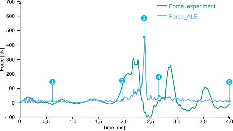
In figure 3 an example of the experimentally determined impact load-time-function is shown as well as the simulated function.
Time [ms]
0,5 1,0 1,5 2,0 2,5 3,0 3,5 4,0
Force
[k
N
]
-100 100 400 500 700
200
0 0 300 600
Force_experiment
Force_ALE
1 2
3
4
5
It can be observed that the peak load of the experiment is smaller than the numerically calculated force. This discrepancy results only from the fact that the experimental values were cut-off at approximately 250 kN caused by the limit of the transmitter.
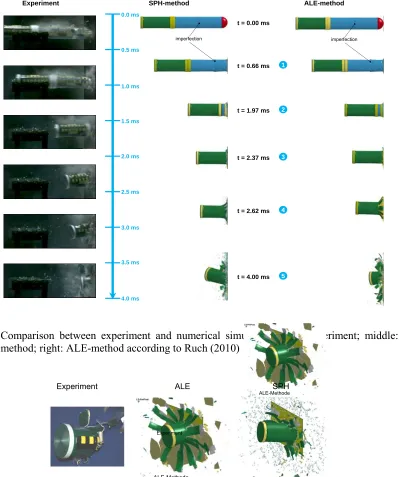
The data which are published in Ruch (2010) show a characteristic curve progression. The first contact of the projectile with the measuring platform (t = 0 ms) leads to inversion of the hemisphere (section 1) and continuous bursting of the cylinder (section 2). Then a load drop at about t = 0.66 ms is registered which is explained by the failure of a production-related imperfection (see figure 4). Furthermore, a continuous bursting of the projectile is observed until the stiff section 3 with the tank-filling reaches the target (approximately at t = 1.7 ms). This phase of the projectile impact leads to the maximal load-entry to the target.
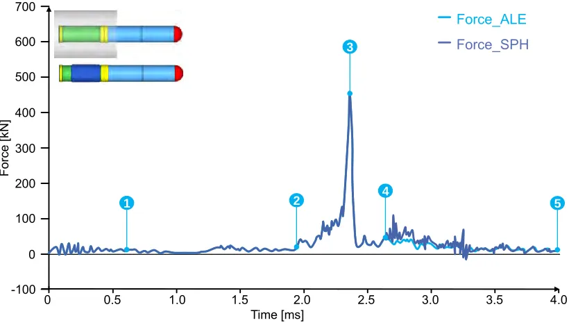
The numerically determined load-time-functions of the impact of water-filled projectiles can be seen in figure 4. It is shown for the ALE-model as well as for the SPH-model. There is no significant difference between the two simulated curves but for the moment of the bursting of the water-filled tank. From this moment the two curves deviates from each other.
Time [ms]
0.5 1.0 1.5 2.0 2.5 3.0 3.5 4.0
Force
[k
N
]
-100 100 400 500 700
200
0 0 300 600
Force_ALE Force_SPH
1 2
3
4
5
Figure 4. Comparison of the two approaches ALE and SPH (projectile design K)
asymmetric. This method allows in contrast to the ALE-method for a droplet or mist formation of the fluid.
imperfection
t = 0.66 ms
t = 1.97 ms
t = 2.37 ms t = 0.00 ms
t = 2.62 ms
t = 4.00 ms
3.5 ms
4.0 ms 3.0 ms 2.5 ms 2.0 ms 1.5 ms 1.0 ms 0.5 ms 0.0 ms
1
2
3
4
5
imperfection
Experiment SPH-method ALE-method
Figure 5. Comparison between experiment and numerical simulations; left: experiment; middle: SPH-method; right: ALE-method according to Ruch (2010)
ALE-Methode
SPH-Methode Experiment
ALE-Methode
SPH-Methode Experiment
SPH
Experiment ALE
Additionally a comparison of the water dispersion of the experiment and the simulated impact is shown in figure 7. On the left hand the water dispersion after an impact experiment with projectile design P is shown. The water dispersion is visible as wet locations on the cardboard. In figure 7 (right), short-takes of the simulated water dispersion of the two different methods ALE and SPH are pictured. It can be seen that the water simulation based on the SPH-method delivers broader water dispersion compared to the ALE-method. This is founded in the meshless character of the SPH formulation. Since the SPH-method is a mesh-free method, a finer dispersal of simulated tank-filling is possible and visible, which is more reflecting the reality.
Figure 7. Water dispersion after projectile impact; left: experiment; middle: ALE-simulation, right: SPH-simulation
Oblique impact (impact angle)
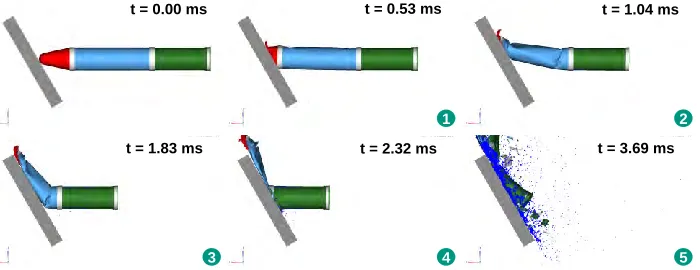
In addition to the modelling of the tank-filling, the variation of the impact angle of 0°, 30° and 60° and a varying impact velocity from 100 m/s to 180 m/s are of particular importance. The impact event with an impact angle of 30° and a velocity of 160 m/s is shown in figure 8 at different time steps.
t = 1.04 ms
2 1
t = 0.53 ms
3 t = 1.83 ms
4 t = 2.32 ms
5 t = 3.69 ms
t = 0.00 ms t = 1.04 ms
2 1
t = 0.53 ms
3 t = 1.83 ms
4 t = 2.32 ms
5 t = 3.69 ms t = 0.00 ms
t = 0.00 ms
Figure 8. Impact of projectile design P at different time steps according to Kreuser et al. (2003), impact angle 30°
The associated time steps of the impact event (figure 8) are marked in the load-time-diagram (figure 9). Here the experimentally measured and the simulated load-time-functions are displayed. The first significant load increase in the simulation can be recognized with the arriving of the first teflon ring
(t = 0.53 ms). With the formation of instability (buckle) in the structure of the first cylindrical part (section 2) the load is decreasing until the stiff section 3 with the tank filling arrives at the measuring platform (t = 1.83 - 2.32 ms). At this moment the maximum force of the event is registered. The load peak at time step 5 arises from the impact of the bulky closure plate of section 3. It is visible that the calculated curve shows a good accordance to the experimentally observed curve of the impact event.
Time [ms]
0.5 1.0 1.5 2.0 2.5 3.0 3.5 4.0 4.5 5.0 5.5 6.0
Forc
e
[k
N
]
-100 100 400 500 700
200
0 0 300 600
V49_Force_z_30 _160 m/s
Force_30 _160 m/s_1mm_SAE10
1
2 3
4
5
Figure 9. Experimental and numerical results of the impact with water filling under an impact angle of 30° (experiment V49 according to Kreuser)
By comparing the load-time-diagrams of an impact angle of 30° (figure 9) with an impact angle of 0° (figure 3), it can be seen that the recorded force is much lower for 30° at nearly equal mass and velocity of the missile. Additionally a less significant single load peak is registered, which is reasonably related to the hydrodynamic effect of the impacting fluid (water).
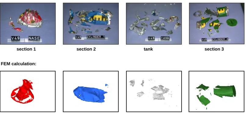
section 1 section 2 tank section 3 Experiment:
FEM calculation:
Figure 10. Fragments after impact; top: experiment V49 according to Kreuser et al. (2003); bottom: simulation SPH
SUMMARY AND CONCLUSIONS
In this work numerical models to analyse the impact of fluid-filled projectiles onto a target have been developed by using LS-DYNA. The key aspects of the work are the detailed investigation of the numerical model with different velocities and/or impact angles and the simulation of the tank-filling with different feasible numerical methods. Within this context, projectile impacts were simulated with the methods ALE and SPH. Some work steps are not yet completed and will be supplemented further with the influence of the effects of the target structure. This is necessary to obtain an effective numerical model able to describe the different influences on the load-time-function of a wide-body aircraft impact. The extended simulation of a concrete target structure with reinforcement and failure behaviour is in progress but not finished yet.
So far, reasonable quantitative correlation between numerical predictions and experimental results were obtained. Nevertheless, it has to be kept in mind that the performance of such a complex computational model depends on the knowledge of the properties and failure phenomena of the individual materials. Furthermore the correct treatment of contact has an influence on the quality of the numerical results. Despite these complexities the obtained results are quite promising.
ACKNOWLEDGEMENT
REFERENCES
Herrmann, N.; Kreuser, K.; Stempniewski, L. (2005). “An experimental Approach to determine Load-Functions for the Impact of Fluid-Filled Projectiles”; 76th Shock and Vibration Symposium, October 30 – November 3, Destin, FL, USA.
Hyvärinen, J.; Hakola, I.; Saarenheimo, A.; Ruch, D.; Herrmann, N.; Schimpfke, T.; Sievers, J. (2007). “Structure Mechanics Simulation of Phenomena during High Energetic Impact”; EUROSAFE 2007 – Towards Convergence of Technical Nuclear Safety Practices in Europe, Berlin, Germany.
Johnson, G.R.; Cook, W. H. (1983). “A Constitutive Model and Data for Metals Subjected to Large Strains, High Strain Rates and High Temperatures”. In: Proceedings of the 7th International Symposium on Ballistics, The Hague, Netherlands, page 541-547.
Kreuser, K., Herrmann, N., Stempniewski, L. (2003). Flugzeugabsturz – Experimentelle Entwicklung von LAST-Zeit-Funktionen – Abschlussbericht zum Unterauftrag des BMWi-Vorhabens RS 1146 73 3060/02 VA-2240.
Kerntechnischer Ausschuss (KTA), KTA 2202 (1980). „Schutz von Kernkraftwerken gegen Flugzeugabsturz und äußere Explosionen, Grundsätze und Lastannahmen“, Regelentwurfsvorlagen 8/80.
Kerntechnischer Ausschuss (KTA), KTA 2203 (1983). „Schutz von Kernkraftwerken gegen Flugzeugabsturz; Auslegung der baulichen Anlagen (bei vorgegebenen Lastannahmen)“, Regelentwurfsvorschlag Dezember 1983.
LS-DYNA (2009). “Keyword User’s Manual”, Volume I, June 2009, Version 971 / release 4 Beta, Livermore Software Technology Corporation (LSTC).
Ruch, D.; Herrmann, N.; Müller, H. S. (2010). “Abschlussbericht zum Vorhaben 1501310 Simulation des mechanischen Verhaltens von steifen Strukturen beim Anprall flüssigkeitsgefüllter Stoßkörper“, Karlsruher Institut für Technologie (KIT), Materialprüfungs- und Forschungsanstalt, MPA Karlsruhe, Karlsruhe, Germany.
Ruch, D.; Herrmann, N.; Müller, H. S. (2009). “Evaluation of Load-Time Functions due to Impact of soft Missiles”; Proceedings of the 17th International Conference on Nuclear Engineering; ICONE17, July 12-16, Brussels, Belgium.