Ductility Behaviour of External SFRSCC
Beam Column Joint- An Experimental Study
Manjunatha K1, Nambiyanna B2, R.Prabhakara3
P.G. Student, Department of Civil Engineering, M.S.Ramaiah Institute of Technology, Bangalore, Karnataka, India1
Assistant Professor, Department of Civil Engineering, M.S.Ramaiah Institute of Technology, Bangalore, Karnataka,
India2
Professor and Head, Department of Civil Engineering, M.S.Ramaiah Institute of Technology, Bangalore, Karnataka,
India3
ABSTRACT:The behaviour of reinforced concrete framed structures in recent earthquakes has alerts poor performances of beam column joints. Beam column joints have a crucial role in the structural integrity of the building. For this reason they must be provided with adequate stiffness and strength to sustain the loads transmitted from beam and columns. Pertaining to these areas, a high percentage of transverse hoops in the core of joints was recommended, which leads congested reinforcement in joints. These difficulties can be overcome by using self-compacting concrete and steel fibres. In the present experimental study an attempt has been made to study the performance of exterior beam column joint by adding fibre content and varying the aspect ratio of fibre in SCC under static load.Various aspects such as load-deflection behaviour, crack width, and ductility have been studied.
KEYWORDS: Exterior Joint, Steel Fibre, Self-Compacting Concrete, Crack Width, Ductility.
I. INTRODUCTION
Normal convectional concrete has been widely used in construction field. Concrete loses its tensile resistance after the formation of multiple cracks, so addition of fibres to concrete has been shown to increase in ductility and energy absorption capacity. Beam column joint is a typical lateral and vertical load resisting member in reinforced concrete structure. The joint should have adequate strength and stiffness to resist the internal force by the framing members. For adequate ductility of beam column joints, use of closely spaced hoops as transverse reinforcement was recommended. Beam column joint plays a crucial role in a multi-storey reinforced concrete framed structure to maintain integrity of structure. Tensile strength in conventional concrete is less which leads formation of multiple cracks. Due to its specific properties, self-compacting concrete (SCC) may contribute to a significant improvement of the quality of concrete structures. SCC gets dense and compacted due to its own self weight in congestion reinforcement of beam column joints.
II. LITERATURE REVIEW
It has been observed from past, many experimental researchers have been carried out an exterior beam column joint to study its exact behaviour under various parameters. Some of the literature review are enlisted below.
1) Conducted a behaviour of steel fiber reinforced high strength concrete beam-column joint. A five bay seven storey RCC moment resisting frame for a general building has been analysed and designed in STAAD PRO as per IS 1893-2002 code procedures and detailed as SP-66(ACI) recommendations. Steel fibres were added in different volume fraction.
It was observed that specimens of beam-column joint by increasing in percentage of steel fiber leads to increase in load carrying capacity, ductility and stiffness. This permits to reduce the anchorage value of reinforcement in the joint region, hence limiting steel congestion in steel joints [6].
2) An experimental investigation was conducted on exterior beam column joint subjected to cyclic loading to study the effect of steel fiber reinforced high performance concrete (SFRHPC). High performance concrete (HPC) of grade M50 with 10% silica fume was used in which steel fibres were added in volume fraction of 0.5%, 1% and 1.5%.
It was found that SFRHPC specimens performed better compared to HPC specimens. It was found that the optimum percentage of steel fiber was 1%. SFRHPC specimens having more load carrying capacity, energy absorption capacity, and displacement ductility factor and curvature ductility factor when compared to HPC specimens. Stiffness degradation of SFRHPC specimens was less for first four cycles and was more for that last cycle [7].
III.OBJECTIVES
The following are the objectives carved from the literature review and gap analysis a) To study the behaviour of exterior beam column joint with or without fibers.
b) To investigate the load deflection characteristics, ductility factor and crack width of sub-assemblies of steel fiber reinforced self-compacting concrete beam column joint under static load through experimental study.
c) To compare the behaviour of all the specimens with the effect of steel fibers in the beam column joint under monotonic load and also to compare the various parameters like ductility factor and crack width.
IV.DETAILS OF EXPERIMENTAL PROGRAMME
During experimental investigation the total 14 of specimens were casted by adding fibre content and varying aspect ratio of fibre in NSC and SCC. Standard test procedure has been adopted in the research laboratory department of civil engineering, M.S.Ramaiah institute of technology, Bangalore.
a)Materials- Ordinary Portland cement 43 grade confirming to IS: 12269 (1987) was used. The fine aggregate used was manufacture sand passing through 4.75 mm IS sieve and having a fineness modulus of 2.43 and specific gravity of 2.39. The coarse aggregate passing through 12.5 mm and retained on 4.75 mm IS sieve having a fineness modulus of 6.25 and specific gravity of 2.79. CLASS F fly ash used as replacement of cement in reasonable quantity. GLENIUM STREAM 2 was used as viscosity modifying agent and GLENIUM B233 used as super plasticizer.
b) Mix proportions for M30 grade- Normal Strength Concrete was obtained based on the IS: 10262-2009, the details of mix proportion thus obtained are given in table 1. The proportion used was 1:2.1:2.46 with W/C ratio of 0.55.
Cement Fine aggregate
Coarse
aggregate Water fiber 380
Kg/m3
802.323 Kg/m3
936.6 Kg/m3
202.5 lit/m3
0.50% 0.75%
c) Mix proportions of SCC concrete for M30 grade,Nan-su method was used. The main consideration in the Nan-su method is that voids present in loose aggregates are filled with paste, and that the packing of the aggregates is minimized. Here it was investigated how maximum packing achieved for different percentages and finally volume ratio of fine aggregates to total aggregates (S/a) was 53% with a packing factor of 1.14.
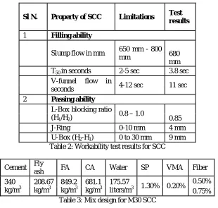
In the present study, various tests like filling ability test, passing ability test and segregation resistance test etc. on fresh SCC were conducted. Trial mixes were conducted from slump flow test, J-ring test, V-funnel test, L-box and U-box test. After passing these tests, successful SCC mixes were arrived. From such successful mixes, choose final mix of proportion after the cubes were cast and tested after 7 days and 28 days. The details of workability test results and mix proportion thus obtained are given in table 2 and table 3 respectively.
Sl N. Property of SCC Limitations Test results
1 Filling ability
Slump flow in mm 650 mm - 800 mm
680 mm T50 in seconds 2-5 sec 3.8 sec
V-funnel flow in
seconds 4-12 sec 11 sec 2 Passing ability
L-Box blocking ratio (H1/H2)
0.8 – 1.0 0.85
J-Ring 0-10 mm 4 mm
U-Box (H2-H1) 0 to 30 mm 9 mm
Table 2: Workability test results for SCC
Cement Fly
ash FA CA Water SP VMA Fiber 340 kg/m3 208.67 kg/m3 849.2 kg/m3 681.1 kg/m3 175.57
liters/m3 1.30% 0.20%
0.50% 0.75% Table 3: Mix design for M30 SCC
d) Designing and detailing of beam column joint specimen- G+5 storey building has been modelled in STAAD PRO software. Dead load and live load combination has been taken into consideration. M30 grade concrete and fe500 grade steel was used. The axial loads, shear forces & moments coming on to the structure has been noted. Critical exterior joint on which maximum load, moment and Shear force are acting have been selected and scaled down to 1/8th of actual forces and moments.
(a) (b)
Fig 1: (a) Reinforcement details of beam column joint, (b) Reinforcement cage for corresponding details
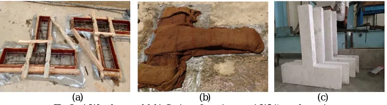
e) Preparation of formwork- The wooden moulds was arranged properly and placed over a smooth surface as shown in fig.2 (a). The inside portion and corners of the moulds were properly greased for easy detachment of formwork from specimen. The Reinforcement cages were placed in the moulds and cover between cage and form kept as 15mm.
f) Mixing of concrete and casting specimen- Mix details are shown in Table 2 and Table 4. The concrete constituents such as cement, fly ash, fine aggregates, coarse aggregates, water, super plasticizer, viscosity modifying agent and steel fibres were weighed accurately and mixed. Mixing was done in pan mixer and mixing was continued until a homogeneous mixture obtained. The concrete was placed into the mould immediately after mixing. Control cubes and cylinders were casted for all the mixes. The test specimens were demoulded from mould at the end of 24 hours and cured under wet gunny bags for 28 days as shown in fig. 2(b). After curing specimens were painted with white colour for proper visualization of crack pattern as shown in fig. 2(c). This procedure was followed for all the 14 specimens.
(a) (b) (c) Fig 2: a) Wooden mould, b) Curing of specimens, c) Whitewash specimens
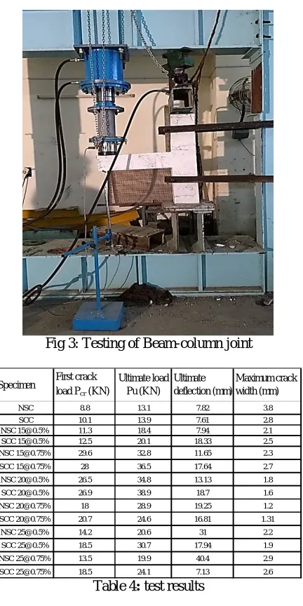
with which type of concrete, fibers aspect ratio and fiber quantity. For an example, specimen SCC [email protected]% denotes, SCC type concrete in which fibres of aspect ratio 20 and 0.5% of fibre quantity were added. A typical loading arrangement is shown in the Fig. 3.
Fig 3: Testing of Beam-column joint
Table 4: test results
V. RESULTS
A)LOAD-DEFLECTION BEHAVIOUR AND CRACK WIDTH
All the specimen results were obtained from the test on beam column joint at 28 days. Table 4 shows first crack load, ultimate load, ultimate deflection and maximum crack width of all specimens. From all the NSC specimens, ultimate load and corresponding deflection of specimens were found to increase as the fibres aspect ratio and content increased, which ensure that ductility enhanced but specimens NSC [email protected]% and [email protected]% failed at early load when compared to other specimens which ensures that providing of percentage and aspect ratio of steel fibre is limited. From all the SCC specimens, specimens with fibres having better results when compared to specimen without fibres. SCC
Specimen First crack load Pcr (KN)
Ultimate load Pu (KN)
Ultimate deflection (mm)
Maximum crack width (mm)
NSC 8.8 13.1 7.82 3.8
SCC 10.1 13.9 7.61 2.8
NSC [email protected]% 11.3 18.4 7.94 2.1
SCC [email protected]% 12.5 20.1 18.33 2.5
NSC [email protected]% 29.6 32.8 11.65 2.3
SCC [email protected]% 28 36.5 17.64 2.7
NSC [email protected]% 26.5 34.8 13.13 1.8
SCC [email protected]% 26.9 38.9 18.7 1.6
NSC [email protected]% 18 28.9 19.25 1.2
SCC [email protected]% 20.7 24.6 16.81 1.31
NSC [email protected]% 14.2 20.6 31 2.2
SCC [email protected]% 18.5 30.7 17.94 1.9
NSC [email protected]% 13.5 19.9 40.4 2.9
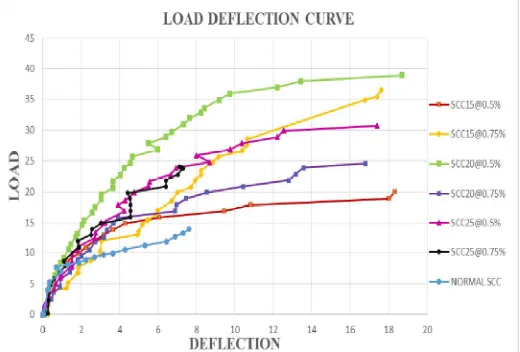
[email protected]% and SCC [email protected]%specimens having a maximum ultimate load for the corresponding deflection when compared to other specimens. Fig. 4, shows a comparative graph of load-deflection curve for NSCspecimens. Fig. 5, shows a comparative graph of load-deflection curve forSCC specimens.
Fig 4: comparative load - deflection graph for NSC specimens
Fig 5: comparative load - deflection graph for SSC specimens
Fig 6: combined load crack width curve for all specimens
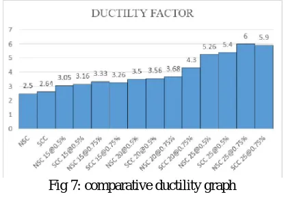
B)DUCTILITY FACTOR
Ductility is defined as the ability to undergo large deformation beyond the initial yield deformation prior to collapse. In the present study ductility factor is defined as the ratio of maximum deflection to yield deflection. It was observed that as the fiber increases the ductility factor got increased. Fig. 7 shows a comparative graph of ductility factor for all specimen.
Fig 7: comparative ductility graph
VI. CONCLUSIONS
Based on the observation from the experimental results the following conclusions were drawn
1) Improved the strength and ductility of the joints was achieved by an addition of steel fibres in the SCC.
2) From the load deflection curve, it was noted that deflection increases with the increasing in fibre quantity upto 0.5% of fiber further deflection decreases with increases in fiber quantity.
3) The ultimate load carrying capacity of SCC [email protected]%specimen was 2.6 times more than specimen without fibre in SCC.
5) It was observed from the maximum crack width, adding fibres in concrete decreases the crack width upto the 20 aspect ratio of fiber further crack width increased with increases in aspect ratio of fiber.
6) Specimens NSC [email protected]% and SCC [email protected]% had crack width 3.1 times and 2.1 times less than specimens without fibres in NSC and SCC respectively.
7) There is certain limits for the quantity and aspect ratio of steel fibres that can be provided in concrete
8) Ductility factor was more for specimens with fibre when compared to specimens without fibres. Ductility factor was increased with increasing in fibre content. It can be inferred that adding of fibers in specimen’s better ductility can be obtained.
9) Ductility factor for a specimens NSC [email protected]% and SCC [email protected]% were 2.4 times more than specimens without fibre in both NSC and SCC.
ACKNOWLEDGEMENT
We sincerely thank management, CE, Principle and Head of department of M.S.Ramaiah Institute of Technology, Bengaluru-560054, affiliated to VTU, Belgaum for the facility provided to conduct the experimentation and all the technical guidance.
REFERENCES
[1] Muthuswamy K.R &Thirugnanam G.S., “Structural Behaviour of Hybrid Fibre Reinforced Concrete Exterior Beam Column Joint Subjected to Cyclic Loading”, International Journal of Civil and Structural Engineering, vol-4, pp 262-273, 2014.
[2] Dr. P. T. Santhosh Kumar., “Effect of Steel Fibres onthe Rheology of Self Compacting Concrete”, 18th International Conference on Rheology of Building Materials, Regensburg, 2009.
[3] Naveen Hooda, JyotiNarwal, Bhupinder Singh, Vivek Varma, Parveen Singh., “Experimental Investigation on Structural Behaviour of Beam Column Joint”,International Journal of Innovative Technology and Exploring Engineering , vol-3, pp 84-88, 2013.
[4] Okamura, H., “Self compacting high performance concrete”, Concrete international, July, PP. 50-54, 1997.
[5] P.Muthupriya, S. C. Boobalan, B. G. Vishnuram.”Behaviour of Fibre Reinforced High Performance Concrete in Exterior Beam Column Joint”, International Journal of Advanced Structural Engineering, 2014.
[6] R. M. SaravanaKumar,E. Ramya, B. Karthick, S. Nalini.,“Experimental Study on Behaviour of Steel Fibre Reinforced High Strength Concrete Beam Column Joint”, International Journal of Engineering Research and Technology, vol-3, pp 1625-1628, 2014.
[7] Asif Abdul Vahab&Ajimon Thomas.,“Effect of Steel Fibre Reinforced High Performance Concrete Exterior Beam Column Joints Subjected To Cyclic Loading”, International Journal of Engineering Research And Technology, vol-3, pp 1409-1414, 2014.
[8] BurcuAkcay& Mehmet Ali Tasdemir.,“Mechanical Behaviour and Fibre Dispersion of Hybrid Steel Fibre Reinforced Self Compacting Concrete”, Construction and Building Materials 28, pp 287-293, 2011.
[9] ShabnumQayoom and Ravi Kumar.” Effect of Grade of Concrete on the Strength of Beam Column Joint”, SSRG International Journal of Civil Engineering, pp 51-53, 2015.
[10] Rekha S Patel, Nambiyanna B, Dr.R.Prabhakara, “An Experimental Study on Effect of Diameter of Rebar on Exterior Beam Column Joint, International Journal of Innovative Research in Science”, Engineering And Technology, vol 4, issue 6, july 2015.
[11] A. Murugesan, D. Shankar, M. Venkatesan, G. S. Thirugnanam., “Seismic Response of RC and SFRC Beam Column Joints”, Integrated Journal of Engineering Research and Technology, pp 8-15, 2015.
[12] Romanbabu M. Oinam, Choudhary. A. M.And Lascar A. I.,” Experimental Study on Beam Column Joint With Fibres Under Cyclic Loading, IOSR Journal of Engineering”, vol-3, pp 13-23, 2013.