GROUP TAB LOCATOR
Introduction
0
Lubrication & Maintenance2
Suspension3
Differential & Driveline5
Brakes6
Clutch7
Cooling8A
Audio8B
Chime/Buzzer8E
Electronic Control Modules8F
Engine Systems8G
Heated Systems8H
Horn8I
Ignition Control8J
Instrument Cluster8L
Lamps8M
Message Systems8N
Power Systems8O
Restraints8P
Speed Control8Q
Vehicle Theft Security8R
Wipers/Washers8W
Wiring9
Engine11
Exhaust System13
Frame & Bumpers14
Fuel System19
Steering21
Transmission and Transfer Case22
Tires/Wheels23
Body24
Heating & Air Conditioning25
Emissions ControlComponent and System Index
Service Manual Comment Forms (Rear of Manual)
NOTE: For New Vehicle Preparation
information, see the separate
INTRODUCTION
TABLE OF CONTENTS
page page
VEHICLE SAFETY CERTIFICATION LABEL
DESCRIPTION . . . 1
VEHICLE IDENTIFICATION NUMBER
DESCRIPTION . . . 1
VEHICLE EMISSION CONTROL INFORMATION (VECI)
DESCRIPTION . . . 3
EQUIPMENT IDENTIFICATION PLATE
DESCRIPTION . . . 3
BODY CODE PLATE
DESCRIPTION . . . 4
INTERNATIONAL VEHICLE CONTROL & DISPLAY SYMBOLS
DESCRIPTION - INTERNATIONAL SYMBOLS . . . 5
FASTENER IDENTIFICATION
DESCRIPTION . . . 6
FASTENER USAGE
DESCRIPTION . . . 9
THREADED HOLE REPAIR
DESCRIPTION . . . 9
METRIC SYSTEM
DESCRIPTION . . . 9
TORQUE REFERENCES
DESCRIPTION . . . 11
VEHICLE SAFETY
CERTIFICATION LABEL
DESCRIPTION
A vehicle safety certification label (Fig. 1) is attached to every Chrysler Corporation vehicle. The label certifies that the vehicle conforms to all appli-cable Federal Motor Vehicle Safety Standards. The label also lists:
• Month and year of vehicle manufacture.
• Gross Vehicle Weight Rating (GVWR). The gross front and rear axle weight ratings (GAWR’s) are based on a minimum rim size and maximum cold tire inflation pressure.
• Vehicle Identification Number (VIN).
• Type of vehicle.
• Type of rear wheels.
• Bar code.
• Month, Day and Hour (MDH) of final assembly.
• Paint and Trim codes.
• Country of origin.
The label is located on the driver-side door shut-face.
VEHICLE IDENTIFICATION
NUMBER
DESCRIPTION
VIN CODING/LOCATIONS
The Vehicle Identification Number (VIN) plate is located on the lower windshield fence near the left A-pillar (Fig. 2). The VIN contains 17 characters that provide data concerning the vehicle. Refer to the VIN decoding chart to determine the identification of a vehicle.
The Vehicle Identification Number is also imprinted on the:
• Body Code Plate.
• Equipment Identification Plate.
• Vehicle Safety Certification Label.
• Frame rail.
To protect the consumer from theft and possible fraud the manufacturer is required to include a Check Digit at the ninth position of the Vehicle Iden-tification Number. The check digit is used by the manufacturer and government agencies to verify the authenticity of the vehicle and official documenta-tion. The formula to use the check digit is not released to the general public.
POSITION INTERPRETATION CODE = DESCRIPTION
1 Country of Origin 3 = Mexico
2 Make B = Dodge
3 Vehicle Type 6 = Incomplete
7 = Truck
4 Gross Vehicle Weight Rating K = 8001-9000
M = 10,001-14,000
5 Vehicle Line C = Ram Cab Chassis/Ram Pick Up
(4x2)
F = Ram Cab Chassis/Ram Pick Up (4x4)
6 Series 2 = 2500
3 = 3500
7 Body Style 3 = Quad Cab
6 = Conventional Cab/Cab Chassis
8 Engine 6 = 5.9L 6 cyl. 24 Valve Diesel
C = 5.9 6cyl. 24 Valve Turbo Diesel H/O
W = 8.0L 10 cyl. MPI Z = 5.9L 8 cyl. MPI-LDC 5 = 5.9L 8cyl. MPI-HDC
9 Check Digit 0 through 9 or X
10 Model Year 2=2002
11 Plant Location M = Lago Alberto Assembly
12 thru 17 Vehicle Build Sequence
Fig. 2 Vehicle 1 - INSTRUMENT PANEL
2 - VEHICLE IDENTIFICATION NUMBER PLATE VIN
2
INTRODUCTION
BR/BE
VEHICLE EMISSION CONTROL
INFORMATION (VECI)
DESCRIPTION
Vehicles equipped with 5.9L V-8 LDC-gas powered engines have a vehicle emission control information (VECI) label.
The label combines both emission control informa-tion and vacuum hose routing. This label is located in the engine compartment in front of the radiator (Fig. 3).
There are unique VECI labels for vehicles built for sale in the country of Canada and Heavy Duty Cycle (HDC) engines. Canadian labels are written in both the English and French languages. For all Canadian vehicles, the label is split into two different labels.
The VECI labels are permanently attached and cannot be removed without defacing information and destroying label.
The VECI label contains the following:
• Engine family and displacement
• Evaporative family
• Emission control system schematic
• Certification application
• Engine timing specifications (if adjustable)
• Idle speeds (if adjustable)
• Spark plug and gap
The 5.9L HDC-gas powered engine will have two labels. One of the labels is located in front of the radiator in the engine compartment (Fig. 3) and will contain vacuum hose routing only. The other is attached to the drivers side of the engine air cleaner housing (Fig. 3).
The VECI label for the 5.9L HDC-gas powered engine will contain the following:
• Engine family and displacement
• Evaporative family
• Certification application
• Engine timing specifications (if adjustable)
• Idle speeds (if adjustable)
• Spark plug and gap
The label for the 8.0L V-10 HDC-gas powered engine is also located in the engine compartment. It is attached to a riveted metal plate located to the right side of the generator (Fig. 4).
EQUIPMENT IDENTIFICATION
PLATE
DESCRIPTION
The Equipment Identification Plate (Fig. 5)is located at the left, front of the inner hood panel. The plate lists information concerning the vehicle as fol-lows:
• The model.
• The wheelbase.
• The VIN (Vehicle Identification Number).
• The T.O.N. (order number).
• The optional and special equipment installed on the vehicle.
Refer to the information listed on the plate when ordering replacement parts.
Fig. 3 VECI Label Location
1 - VEHICLE EMISSION CONTROL INFORMATION (VECI) LABEL 2 - VECI LABEL (5.9L HDC FOR CANADA ONLY)
3 - VECI LABEL (5.9L HDC ONLY) (INCLUDES CANADA)
Fig. 4 VECI Label Location—8.0L V-10 Engine 1 - VECI LABEL
BODY CODE PLATE
DESCRIPTION
The Body Code Plate (Fig. 6) is located on the floor pan under the passenger seat or attached to the front face of the radiator closure panel. There are seven lines of information on the body code plate. Lines 5, 6, and 7 are not used to define service information. Information reads from left to right, starting with line 4 in the center of the plate to line 1 at the bot-tom of the plate.
The last code imprinted on a vehicle code plate will be followed by the imprinted word END. When two vehicle code plates are required, the last available spaces on the first plate will be imprinted with the letters CTD (for continued).
When a second vehicle code plate is necessary, the first four spaces on each row will not be used because of the plate overlap.
BODY CODE PLATE—LINE 4
DIGITS 1 THROUGH 12
Vehicle Order Number
DIGITS 13, 14, AND 15
Transmission Codes
• DGP = 4–speed Automatic (47RE)
• DGT = 4–speed Automatic (46RE)
• DGK = 4–speed Automatic (42RE)
• DDP = 5–speed Manual (NVG-4500)
• DDX = 5–speed Manual (NVG-4500 Heavy Duty)
• DDC = 5–speed Manual (NVG-3500)
• DEE = 6–speed Manual (NVG-5600)
DIGITS 16, 17, AND 18
Car Line Shell
• BR1 = 1500 4 X 2
• BE1 = 1500 4 X 2
• BR6 = 1500 4 X 4
• BE6 = 1500 4 X 4
• BR2 = 2500 4 X 2
• BE2 = 2500 4 X 2
• BR7 = 2500 4 X 4
• BE7 = 2500 4 X 4
• BR3 = 3500 4 X 2
• BE3 = 3500 4 X 2
• BR8 = 3500 4 X 4
• BE8 = 3500 4 X 4
DIGIT 19
Price Class
• L = Ram Truck (All)
DIGITS 20 AND 21
Body Type
• 31 = Ram Truck Club Cab (138.7 in. Wheel Base)
• 32 = Ram Truck Club Cab (154.7 in. Wheel Base)
• 33 = Ram Truck Quad Cab (138.7 in. Wheel Base)
• 34 = Ram Truck Quad Cab (154.7 in. Wheel Base)
• 61 = Ram Truck (118.7 in. Wheel Base)
• 62 = Ram Truck (134.7 in. Wheel Base)
• 63 = Ram Truck Cab Chassis (138.7 in. Wheel Base)
Fig. 5 Equipment Identification Plate
Fig. 6 Body Code Plate 1 - PRIMARY PAINT
2 - SECONDARY PAINT 3 - TRANSMISSION CODE 4 - VEHICLE MODEL NUMBER 5 - ENGINE CODE
6 - INTERIOR TRIM CODE
7 - VEHICLE IDENTIFICATION NUMBER 8 - TAILGATE CODE
9 - CARGO BOX CODE 10 - TAILGATE TRIM CODE 11 - BODY-IN-WHITE SEQUENCE 12 - MARKET CODE
13 - SPECIES CODE 14 - PAINT PROCEDURE 15 - VEHICLE ORDER NUMBER
4
INTRODUCTION
BR/BE
• 64 = Ram Truck Cab Chassis (162.7 in. Wheel Base)
BODY CODE PLATE—LINE 3
DIGITS 1,2, AND 3
Paint Procedure
• APA = Monotone
• AP9 = Special
• APB = Two-tone (Waterfall)
• APC = Two-tone (Centerband)
• APD = Two-tone (Lower break)
DIGIT 4
Open Space
DIGITS 5 THROUGH 8
Primary Paint
Refer to Group 23, Body for color codes.
DIGIT 9
Open Space
DIGITS 10 THROUGH 13
Secondary Paint
DIGIT 14
Open Space
DIGITS 15 THROUGH 18
Interior Trim Code
DIGIT 19
Open Space
DIGITS 20, 21, AND 22
Engine Code
• EML = 5.9 L 8 cyl. MPI Gasoline
• EMM = 5.9 L 8 cyl. MPI Gasoline (Heavy Duty)
• ETC = 5.9 L 6 cyl. Turbo Diesel
• EWA = 8.0 L 10 cyl. MPI Gasoline
BODY CODE PLATE—LINE 2
DIGIT 1 Open Space
DIGITS 2 AND 3 Species Code. (Used for Manufacturing)
DIGIT 4
Open Space
DIGIT 5
Market Code
• B = International
• C = Canada
• M = Mexico
• U = United States
DIGIT 6
Open Space
DIGITS 7 THROUGH 23
Vehicle Identification Number (VIN)
Refer to Vehicle Identification Number (VIN) para-graph for proper breakdown of VIN code.
BODY CODE PLATE—LINE 1
DIGITS 1 THROUGH 6 Body-in-white assembly sequence.
DIGIT 7
Open Space
DIGIT 8 Tailgate trim code.
DIGIT 9
Open Space
DIGITS 10 THROUGH 12 Cargo box code
• XBS = Sweptline
DIGIT 13
Open Space
DIGITS 14 THROUGH 16 Tailgate code
• MWD = Plain Tailgate
• MPB = Tailgate Applique (Black)
INTERNATIONAL VEHICLE
CONTROL & DISPLAY
SYMBOLS
DESCRIPTION - INTERNATIONAL SYMBOLS
The graphic symbols illustrated in the following International Control and Display Symbols Chart are used to identify various instrument controls. The symbols correspond to the controls and displays that are located on the instrument panel.
FASTENER IDENTIFICATION
DESCRIPTION
The SAE bolt strength grades range from grade 2 to grade 8. The higher the grade number, the greater the bolt strength. Identification is determined by the line marks on the top of each bolt head. The actual bolt strength grade corresponds to the number of line marks plus 2. The most commonly used metric bolt strength classes are 9.8 and 10.9. The metric strength class identification number is imprinted on the head of the bolt. The higher the class number, the greater the bolt strength. Some metric nuts are imprinted with a single-digit strength class on the nut face. Refer to the Fastener Identification and Fastener Strength Charts (Fig. 7) and (Fig. 8).
INTERNATIONAL SYMBOLS
1 High Beam 13 Rear Window Washer
2 Fog Lamps 14 Fuel
3 Headlamp, Parking Lamps, Panel Lamps 15 Engine Coolant Temperature 4 Turn Warning 16 Battery Charging Condition
5 Hazard Warning 17 Engine Oil
6 Windshield Washer 18 Seat Belt 7 Windshield Wiper 19 Brake Failure 8 Windshield Wiper and Washer 20 Parking Brake 9 Windscreen Demisting and Defrosting 21 Front Hood 10 Ventilating Fan 22 Rear hood (Decklid) 11 Rear Window Defogger 23 Horn
12 Rear Window Wiper 24 Lighter
6
INTRODUCTION
BR/BE
Fig. 7 FASTENER IDENTIFICATION
Fig. 8 FASTENER STRENGTH
8
INTRODUCTION
BR/BE
FASTENER USAGE
DESCRIPTION
WARNING: USE OF AN INCORRECT FASTENER MAY RESULT IN COMPONENT DAMAGE OR PER-SONAL INJURY.
Figure art, specifications and torque references in this Service Manual are identified in metric and SAE format.
During any maintenance or repair procedures, it is important to salvage all fasteners (nuts, bolts, etc.) for reassembly. If the fastener is not salvageable, a fastener of equivalent specification must be used.
THREADED HOLE REPAIR
DESCRIPTION
Most stripped threaded holes can be repaired using a Helicoilt. Follow the vehicle or Helicoilt recommen-dations for application and repair procedures.
METRIC SYSTEM
DESCRIPTION
The metric system is based on quantities of one, ten, one hundred, one thousand and one million.
The following chart will assist in converting metric units to equivalent English and SAE units, or vise versa.
CONVERSION FORMULAS AND EQUIVALENT VALUES
MULTIPLY BY TO GET MULTIPLY BY TO GET
in-lbs x 0.11298 = Newton Meters (N·m)
N·m x 8.851 = in-lbs
ft-lbs x 1.3558 = Newton Meters (N·m)
N·m x 0.7376 = ft-lbs
Inches Hg (60° F) x 3.377 = Kilopascals (kPa) kPa x 0.2961 = Inches Hg psi x 6.895 = Kilopascals (kPa) kPa x 0.145 = psi
Inches x 25.4 = Millimeters (mm) mm x 0.03937 = Inches
Feet x 0.3048 = Meters (M) M x 3.281 = Feet
Yards x 0.9144 = Meters M x 1.0936 = Yards
mph x 1.6093 = Kilometers/Hr. (Km/h)
Km/h x 0.6214 = mph
Feet/Sec x 0.3048 = Meters/Sec (M/S) M/S x 3.281 = Feet/Sec mph x 0.4470 = Meters/Sec (M/S) M/S x 2.237 = mph
Kilometers/Hr. (Km/h) x 0.27778 = Meters/Sec (M/S) M/S x 3.600 Kilometers/Hr. (Km/h)
COMMON METRIC EQUIVALENTS
1 inch = 25 Millimeters 1 Cubic Inch = 16 Cubic Centimeters 1 Foot = 0.3 Meter 1 Cubic Foot = 0.03 Cubic Meter
1 Yard = 0.9 Meter 1 Cubic Yard = 0.8 Cubic Meter 1 Mile = 1.6 Kilometers
METRIC CONVERSION CHART
10
INTRODUCTION
BR/BE
TORQUE REFERENCES
DESCRIPTION
Individual Torque Charts appear within many or the Groups. Refer to the Standard Torque
Specifica-tions Chart for torque references not listed in the individual torque charts.
LUBRICATION & MAINTENANCE
TABLE OF CONTENTS
page page
INTERNATIONAL SYMBOLS
DESCRIPTION . . . 1
PARTS & LUBRICANT RECOMMENDATION
STANDARD PROCEDURE STANDARD PROCEDURE
-CLASSIFICATION OF LUBRICANTS . . . 1
FLUID TYPES
DESCRIPTION . . . 2 OPERATION . . . 6
FLUID CAPACITIES
SPECIFICATIONS . . . 6
MAINTENANCE SCHEDULES
DESCRIPTION . . . 7
JUMP STARTING
STANDARD PROCEDURE
STANDARD PROCEDURE - JUMP
STARTING . . . 7
HOISTING
STANDARD PROCEDURE
STANDARD PROCEDURE - HOISTING . . . 9
TOWING
STANDARD PROCEDURE
STANDARD PROCEDURE - TOWING . . . 10
INTERNATIONAL SYMBOLS
DESCRIPTION
DaimlerChrysler Corporation uses international symbols to identify engine compartment lubricant and fluid inspection and fill locations (Fig. 1).
PARTS & LUBRICANT
RECOMMENDATION
STANDARD PROCEDURE - CLASSIFICATION OF
LUBRICANTS
Only lubricants that are endorsed by the following organization should be used to service a DaimlerChrysler Corporation vehicle.
• Society of Automotive Engineers (SAE) • American Petroleum Institute (API) (Fig. 6) • National Lubricating Grease Institute (NLGI) (Fig. 2)
Lubricating grease is rated for quality and usage by the NLGI. All approved products have the NLGI symbol (Fig. 2) on the label. At the bottom NLGI symbol is the usage and quality identification letters. Wheel bearing lubricant is identified by the letter “G”. Chassis lubricant is identified by the latter “L”. The letter following the usage letter indicates the quality of the lubricant. The following symbols indi-cate the highest quality.
When service is required, DaimlerChrysler Corpo-ration recommends that only Mopart brand parts, lubricants and chemicals be used. Mopar provides the best engineered products for servicing DaimlerChrysler Corporation vehicles.
Fig. 1 International Symbols
Fig. 2 NLGI Symbol 1 - WHEEL BEARINGS
2 - CHASSIS LUBRICATION
FLUID TYPES
DESCRIPTION - FUEL REQUIREMENTS - GAS
ENGINES
Your engine is designed to meet all emissions reg-ulations and provide excellent fuel economy and per-formance when using high quality unleaded gasoline having an octane rating of 87. The use of premium gasoline is not recommended. The use of premium gasoline will provide no benefit over high quality reg-ular gasoline, and in some circumstances may result in poorer performance.
Light spark knock at low engine speeds is not harmful to your engine. However, continued heavy spark knock at high speeds can cause damage and immediate service is required. Engine damage result-ing from operation with a heavy spark knock may not be covered by the new vehicle warranty.
Poor quality gasoline can cause problems such as hard starting, stalling and hesitations. If you experi-ence these symptoms, try another brand of gasoline before considering service for the vehicle.
Over 40 auto manufacturers world-wide have issued and endorsed consistent gasoline specifications (the Worldwide Fuel Charter, WWFC) to define fuel properties necessary to deliver enhanced emissions, performance and durability for your vehicle. We rec-ommend the use of gasolines that meet the WWFC specifications if they are available.
REFORMULATED GASOLINE
Many areas of the country require the use of cleaner burning gasoline referred to as “reformulat-ed” gasoline. Reformulated gasoline contain oxygen-ates, and are specifically blended to reduce vehicle emissions and improve air quality.
We strongly supports the use of reformulated gas-oline. Properly blended reformulated gasoline will provide excellent performance and durability for the engine and fuel system components.
GASOLINE/OXYGENATE BLENDS
Some fuel suppliers blend unleaded gasoline with oxygenates such as 10% ethanol, MTBE, and ETBE. Oxygenates are required in some areas of the country during the winter months to reduce carbon monoxide emissions. Fuels blended with these oxygenates may be used in your vehicle.
CAUTION: DO NOT use gasoline containing METH-ANOL. Gasoline containing methanol may damage critical fuel system components.
MMT IN GASOLINE
MMT is a manganese-containing metallic additive that is blended into some gasoline to increase octane. Gasoline blended with MMT provide no performance advantage beyond gasoline of the same octane num-ber without MMT. Gasoline blended with MMT reduce spark plug life and reduce emission system performance in some vehicles. We recommend that gasolines free of MMT be used in your vehicle. The MMT content of gasoline may not be indicated on the gasoline pump; therefore, you should ask your gaso-line retailer whether or not his/her gasogaso-line contains MMT.
It is even more important to look for gasoline with-out MMT in Canada because MMT can be used at levels higher than allowed in the United States. MMT is prohibited in Federal and California refor-mulated gasoline.
SULFUR IN GASOLINE
If you live in the northeast United States, your vehicle may have been designed to meet California low emission standards with Cleaner-Burning Cali-fornia reformulated gasoline with low sulfur. If such fuels are not available in states adopting California emission standards, your vehicles will operate satis-factorily on fuels meeting federal specifications, but emission control system performance may be adversely affected. Gasoline sold outside of California is permitted to have higher sulfur levels which may affect the performance of the vehicle’s catalytic con-verter. This may cause the Malfunction Indicator Lamp (MIL), Check Engine or Service Engine Soon light to illuminate. We recommend that you try a dif-ferent brand of unleaded gasoline having lower sulfur to determine if the problem is fuel related prior to returning your vehicle to an authorized dealer for service.
CAUTION: If the Malfunction Indicator Lamp (MIL), Check Engine or Service Engine Soon light is flash-ing, immediate service is required; see on-board diagnostics system section.
MATERIALS ADDED TO FUEL
All gasoline sold in the United States and Canada are required to contain effective detergent additives. Use of additional detergents or other additives is not needed under normal conditions.
FUEL SYSTEM CAUTIONS
CAUTION: Follow these guidelines to maintain your vehicle’s performance:
• The use of leaded gas is prohibited by Federal law. Using leaded gasoline can impair engine perfor-mance, damage the emission control system, and could result in loss of warranty coverage.
• An out-of-tune engine, or certain fuel or ignition malfunctions, can cause the catalytic converter to overheat. If you notice a pungent burning odor or some light smoke, your engine may be out of tune or malfunctioning and may require immediate service. Contact your dealer for service assistance.
• When pulling a heavy load or driving a fully loaded vehicle when the humidity is low and the tem-perature is high, use a premium unleaded fuel to help prevent spark knock. If spark knock persists, lighten the load, or engine piston damage may result. • The use of fuel additives which are now being sold as octane enhancers is not recommended. Most of these products contain high concentrations of methanol. Fuel system damage or vehicle perfor-mance problems resulting from the use of such fuels or additives is not the responsibility of DaimlerChrysler Corporation and may not be covered under the new vehicle warranty.
NOTE: Intentional tampering with emissions control systems can result in civil penalties being assessed against you.
DESCRIPTION FUEL REQUIREMENTS
-DIESEL ENGINE
DESCRIPTION
WARNING: Do not use alcohol or gasoline as a fuel blending agent. They can be unstable under certain conditions and hazardous or explosive when mixed with diesel fuel.
Use good quality diesel fuel from a reputable sup-plier in your Dodge truck. For most year-round ser-vice, number 2 diesel fuel meeting ASTM specification D-975 will provide good performance. If the vehicle is exposed to extreme cold (below 0°F/-18°C), or is required to operate at colder-than-normal conditions for prolonged periods, use climatized No. 2 diesel fuel or dilute the No. 2 diesel fuel with 50% No. 1 diesel fuel. This will provide better protection from fuel gelling or wax-plugging of the fuel filters.
Diesel fuel is seldom completely free of water. To prevent fuel system trouble, including fuel line freez-ing in winter, drain the accumulated water from the fuel/water separator using the fuel/water separator drain provided. If you buy good-quality fuel and fol-low the cold-weather advice above, fuel conditioners should not be required in your vehicle. If available in your area, a high cetane “premium” diesel fuel may
offer improved cold starting and warm-up perfor-mance.
DESCRIPTION - ENGINE COOLANT
WARNING: ANTIFREEZE IS AN ETHYLENE GLYCOL BASE COOLANT AND IS HARMFUL IF SWAL-LOWED OR INHALED. IF SWALSWAL-LOWED, DRINK TWO GLASSES OF WATER AND INDUCE VOMIT-ING. IF INHALED, MOVE TO FRESH AIR AREA. SEEK MEDICAL ATTENTION IMMEDIATELY. DO NOT STORE IN OPEN OR UNMARKED CONTAINERS. WASH SKIN AND CLOTHING THOROUGHLY AFTER COMING IN CONTACT WITH ETHYLENE GLYCOL. KEEP OUT OF REACH OF CHILDREN. DISPOSE OF GLYCOL BASE COOLANT PROPERLY, CONTACT YOUR DEALER OR GOVERNMENT AGENCY FOR LOCATION OF COLLECTION CENTER IN YOUR AREA. DO NOT OPEN A COOLING SYSTEM WHEN THE ENGINE IS AT OPERATING TEMPERATURE OR HOT UNDER PRESSURE, PERSONAL INJURY CAN RESULT. AVOID RADIATOR COOLING FAN WHEN ENGINE COMPARTMENT RELATED SERVICE IS PERFORMED, PERSONAL INJURY CAN RESULT.
CAUTION: Use of Propylene Glycol based coolants is not recommended, as they provide less freeze protection and less corrosion protection.
The cooling system is designed around the coolant. The coolant must accept heat from engine metal, in the cylinder head area near the exhaust valves and engine block. Then coolant carries the heat to the radiator where the tube/fin radiator can transfer the heat to the air.
The use of aluminum cylinder blocks, cylinder heads, and water pumps requires special corrosion protection. Mopart Antifreeze/Coolant, 5 Year/100,000 Mile Formula (MS-9769), or the equiva-lent ethylene glycol base coolant with organic corro-sion inhibitors (called HOAT, for Hybrid Organic Additive Technology) is recommended. This coolant offers the best engine cooling without corrosion when mixed with 50% Ethylene Glycol and 50% distilled water to obtain a freeze point of -37°C (-35°F). If it loses color or becomes contaminated, drain, flush, and replace with fresh properly mixed coolant solu-tion.
CAUTION: MoparT Antifreeze/Coolant, 5 Year/100,000 Mile Formula (MS-9769) may not be mixed with any other type of antifreeze. Mixing of coolants other than specified (non-HOAT or other HOAT), may result in engine damage that may not be covered under the new vehicle warranty, and decreased corrosion protection.
COOLANT PERFORMANCE
The required ethylene-glycol (antifreeze) and water mixture depends upon climate and vehicle operating conditions. The coolant performance of various mix-tures follows:
Pure Water-Water can absorb more heat than a
mixture of water and ethylene-glycol. This is for pur-pose of heat transfer only. Water also freezes at a higher temperature and allows corrosion.
100 percent Ethylene-Glycol-The corrosion inhibiting additives in ethylene-glycol need the pres-ence of water to dissolve. Without water, additives form deposits in system. These act as insulation causing temperature to rise to as high as 149°C (300°F). This temperature is hot enough to melt plas-tic and soften solder. The increased temperature can result in engine detonation. In addition, 100 percent ethylene-glycol freezes at -22°C (-8°F).
50/50 Ethylene-Glycol and Water-Is the
recom-mended mixture, it provides protection against freez-ing to -37°C (-34°F). The antifreeze concentration
must always be a minimum of 44 percent,
year-round in all climates. If percentage is lower, engine parts may be eroded by cavitation. Maximum protec-tion against freezing is provided with a 68 percent antifreeze concentration, which prevents freezing down to -67.7°C (-90°F). A higher percentage will freeze at a warmer temperature. Also, a higher per-centage of antifreeze can cause the engine to over-heat because specific over-heat of antifreeze is lower than that of water.
CAUTION: Richer antifreeze mixtures cannot be measured with normal field equipment and can cause problems associated with 100 percent ethyl-ene-glycol.
COOLANT SELECTION AND ADDITIVES
NOTE: Refer to the vehicle’s coolant bottle to iden-tify HOAT or Non-HOAT coolant. Non-HOAT coolant is green in color.
The use of aluminum cylinder blocks, cylinder heads and water pumps requires special corrosion protection. Only Mopart Antifreeze/Coolant, 5 Year/100,000 Mile Formula (glycol base coolant with corrosion inhibitors called HOAT, for Hybrid Organic Additive Technology) is recommended. This coolant offers the best engine cooling without corrosion when mixed with 50% distilled water to obtain to obtain a freeze point of -37°C (-35°F). If it loses color or becomes contaminated, drain, flush, and replace with fresh properly mixed coolant solution.
CAUTION: Do not use coolant additives that are claimed to improve engine cooling.
DESCRIPTION—ENGINE OIL
API SERVICE GRADE CERTIFIED
WARNING: NEW OR USED ENGINE OIL CAN BE IRRITATING TO THE SKIN. AVOID PROLONGED OR REPEATED SKIN CONTACT WITH ENGINE OIL. CONTAMINANTS IN USED ENGINE OIL, CAUSED BY INTERNAL COMBUSTION, CAN BE HAZARDOUS TO YOUR HEALTH. THOROUGHLY WASH EXPOSED SKIN WITH SOAP AND WATER. DO NOT WASH SKIN WITH GASOLINE, DIESEL FUEL, THINNER, OR SOLVENTS, HEALTH PROBLEMS CAN RESULT. DO NOT POLLUTE, DISPOSE OF USED ENGINE OIL PROPERLY. CONTACT YOUR DEALER OR GOVERN-MENT AGENCY FOR LOCATION OF COLLECTION CENTER IN YOUR AREA.
Standard engine-oil identification notations have been adopted to aid in the proper selection of engine oil. The identifying notations are located on the label of engine oil plastic bottles and the top of engine oil cans.
In diesel engines, use an engine oil that conforms to API Service Grade CF-4 or CG-4/SH (Fig. 3). MOPARt provides an engine oil that conforms to this particular grade.
SAE VISCOSITY
An SAE viscosity grade is used to specify the vis-cosity of engine oil. SAE 15W–40 specifies a multiple viscosity engine oil.
When choosing an engine oil, consider the range of temperatures the vehicle will be operated in before the next oil change. Select an engine oil that is best suited to your area’s particular ambient temperature range and variation. For diesel engines, refer to (Fig. 4).
Fig. 3 API Service Grade Certification Label—Diesel Engine Oil
0 - 4
LUBRICATION & MAINTENANCE
BR/BE
DESCRIPTION - ENGINE OIL
WARNING: NEW OR USED ENGINE OIL CAN BE IRRITATING TO THE SKIN. AVOID PROLONGED OR REPEATED SKIN CONTACT WITH ENGINE OIL. CONTAMINANTS IN USED ENGINE OIL, CAUSED BY INTERNAL COMBUSTION, CAN BE HAZARDOUS TO YOUR HEALTH. THOROUGHLY WASH EXPOSED SKIN WITH SOAP AND WATER. DO NOT WASH SKIN WITH GASOLINE, DIESEL FUEL, THINNER, OR SOLVENTS, HEALTH PROBLEMS CAN RESULT. DO NOT POLLUTE, DISPOSE OF USED ENGINE OIL PROPERLY. CONTACT YOUR DEALER OR GOVERN-MENT AGENCY FOR LOCATION OF COLLECTION CENTER IN YOUR AREA.
API SERVICE GRADE CERTIFIED
Use an engine oil that is API Service Grade Certi-fied. MOPARt provides engine oils that conform to this service grade.
SAE VISCOSITY
An SAE viscosity grade is used to specify the vis-cosity of engine oil. Use only engine oils with multi-ple viscosities such as 5W-30 or 10W-30. These oils are specified with a dual SAE viscosity grade which indicates the cold-to-hot temperature viscosity range. Select an engine oil that is best suited to your par-ticular temperature range and variation (Fig. 5).
ENERGY CONSERVING OIL
An Energy Conserving type oil is recommended for gasoline engines. The designation of ENERGY CON-SERVING is located on the label of an engine oil con-tainer.
CONTAINER IDENTIFICATION
Standard engine oil identification notations have been adopted to aid in the proper selection of engine oil. The identifying notations are located on the label of engine oil plastic bottles and the top of engine oil cans (Fig. 6).
DESCRIPTION - AXLE LUBRICATION
A multi-purpose, hypoid gear lubricant which con-forms to the following specifications should be used. Mopar Hypoid Gear Lubricant conforms to these specifications.
NOTE: Trac-lokT and Powr-lokT equipped axles require a friction modifier be added to the lubricant.
FRONT AXLE
• The lubricant should have MIL-L-2105C and API GL 5 quality specifications.
• Lubricant is a thermally stable SAE 80W90.
REAR AXLE
• The lubricant should have MIL-L-2105C and API GL 5 quality specifications.
• Lubricant is a thermally stable SAE 90W.
DESCRIPTION - TRANSFER CASE - NV241
Recommended lubricant for the NV241 transfer case is Mopart ATF+4, type 9602, Automatic Trans-mission Fluid.
DESCRIPTION - MANUAL TRANSMISSION
Mopart Manual Transmission Lubricant is recom-mended or equivalent for use in the manual trans-missions.
Fig. 4 Engine Oil Viscosity Recommendation— Diesel Engines
Fig. 5 Temperature/Engine Oil Viscosity
Fig. 6 API Symbol
DESCRIPTION - AUTOMATIC TRANSMISSION
FLUID
NOTE: Refer to the maintenance schedules in this group for the recommended maintenance (fluid/filter change) intervals for this transmission.
NOTE: Refer to Service Procedures in this group for fluid level checking procedures.
Mopart ATF +4, type 9602, Automatic Transmis-sion Fluid is the recommended fluid for DaimlerChrysler automatic transmissions.
Dexron II fluid IS NOT recommended. Clutch chatter can result from the use of improper fluid.
Mopart ATF +4, type 9602, Automatic Transmis-sion Fluid when new is red in color. The ATF is dyed red so it can be identified from other fluids used in the vehicle such as engine oil or antifreeze. The red color is not permanent and is not an indicator of fluid condition. As the vehicle is driven, the ATF will begin to look darker in color and may eventually become brown. This is normal. A dark brown/black fluid accompanied with a burnt odor and/or deterioration in shift quality may indicate fluid deterioration or transmission component failure.
FLUID ADDITIVES
DaimlerChrysler strongly recommends against the addition of any fluids to the transmission, other than those automatic transmission fluids listed above. Exceptions to this policy are the use of special dyes to aid in detecting fluid leaks.
Various “special” additives and supplements exist that claim to improve shift feel and/or quality. These additives and others also claim to improve converter clutch operation and inhibit overheating, oxidation, varnish, and sludge. These claims have not been sup-ported to the satisfaction of DaimlerChrysler and these additives must not be used. The use of trans-mission “sealers” should also be avoided, since they may adversely affect the integrity of transmission seals.
OPERATION - AUTOMATIC TRANSMISSION
FLUID
The automatic transmission fluid is selected based upon several qualities. The fluid must provide a high level of protection for the internal components by providing a lubricating film between adjacent metal components. The fluid must also be thermally stable so that it can maintain a consistent viscosity through a large temperature range. If the viscosity stays con-stant through the temperature range of operation,
transmission operation and shift feel will remain sistent. Transmission fluid must also be a good con-ductor of heat. The fluid must absorb heat from the internal transmission components and transfer that heat to the transmission case.
FLUID CAPACITIES
SPECIFICATIONS
FLUID CAPACITIES
DESCRIPTION SPECIFICATION
FUEL TANK
2500 Series Club Cab and Quad Cab with 6.5’ Short Box
129 L (34 gal.)*****
All 8’ Long Box 132 L (35 gal.)***** All Cab/Chassis Models 132 L (35 gal.)*****
ENGINE OIL WITH FILTER
5.9L 4.7 L (5.0 qts.) 8.0L 6.6 L (7.0 qts.) 5.9L DIESEL 10.4 L (11.0 qts.)
COOLING SYSTEM
5.9L 19 L (20 qts.)**** 8.0L 24.5 L (26.0 qts.)**** 5.9L DIESEL 22.7 L (24.0 qts.)****
POWER STEERING
Power steering fluid capacities are dependent on engine/chassis options as well as steering gear/cooler options. Depending on type and size of internal cooler, length and inside diameter of cooler lines, or use of an auxiliary cooler, these capacities may vary. Refer to 19, Steering for proper fill and bleed
procedures.
AUTOMATIC TRANSMISSION
Service Fill - 46RE 3.8 L (4.0 qts.) O-haul - 46RE 9-9.5L (19-20 pts.)* Service Fill - 47RE 3.8 L (4.0 qts.)
O-haul - 47RE 14-16 L (29-33 pts.)*
0 - 6
LUBRICATION & MAINTENANCE
BR/BE
DESCRIPTION SPECIFICATION
Dry fill capacity Depending on type and size of internal cooler, length and inside diameter of cooler lines, or use of an auxiliary cooler, these figures may
vary. (Refer to 21 - TRANSMISSION/TRANSAXLE/ AUTOMATIC/FLUID - STANDARD PROCEDURE)
MANUAL TRANSMISSION
NV4500 3.8 L (8.0 pts.)
NV5600 4.5 L (9.5 pts.)
TRANSFER CASE
NV241 2.18 L (4.61 pts.) NV241 HD 3.08 L (6.51 pts.)
FRONT AXLE ± .03 L (1 oz)
248-RBI (Model 60) 4.0 L (8.5 pts.)
REAR AXLE ± .03 L (1 oz)
248-RBI (Model 60) 2WD 2.9 L (6.1 pts.) 248-RBI (Model 60) 4WD 3.4 L (7.2 pts.)
267-RBI (Model 70)
2WD 3.3 L (7.0 pts.) 267-RBI (Model 70)
4WD 3.6 L (7.6 pts.) 286-RBI (Model 80)
2WD 3.2 L (6.8 pts.) 286-RBI (Model 80)
4WD 4.8 L (10.1 pts.)
REAR AXLE - LIMITED SLIP DIFFERENTIAL ± .03 L (1 oz)
248-RBI (Model 60) 2WD 2.8 L (5.9 pts.) 248-RBI (Model 60) 4WD 3.2 L (6.8 pts.)
267-RBI (Model 70)
2WD 3.1 L (6.5 pts.) 267-RBI (Model 70)
4WD 3.4 L (7.2 pts.)
286-RBI (Model 80)
2WD 3.0 L (6.3 pts.) 286-RBI (Model 80)
4WD 4.5 L (9.5 pts.)
FRICTION MODIFIER ± .03 L (1 oz)
248-RBI (Model 60) 2WD 0.15 L (5 oz) 248-RBI (Model 60) 4WD 0.18 L (6 oz)
267-RBI (Model 70)
2WD 0.21 L (7 oz)
DESCRIPTION SPECIFICATION
267-RBI (Model 70)
4WD 0.24 L (8 oz)
286-RBI (Model 80)
2WD 0.21 L (7 oz)
286-RBI (Model 80)
4WD 0.30 L (10 oz)
**** Includes 0.9L (1.0 qts.) for coolant reservoir.
*****Nominal refill capacities are shown. A variation may be observed from vehicle to vehicle due to
manufacturing tolerance and refill procedure.
MAINTENANCE SCHEDULES
DESCRIPTION
9Maintenance Schedule Information not included in this section, is located in the appropriate Owner’s Manual.9
JUMP STARTING
STANDARD PROCEDURE - JUMP STARTING
WARNING: REVIEW ALL SAFETY PRECAUTIONS AND WARNINGS IN GROUP 8A, BATTERY/START-ING/CHARGING SYSTEMS DIAGNOSTICS.
• DO NOT JUMP START A FROZEN BATTERY, PERSONAL INJURY CAN RESULT.
• DO NOT JUMP START WHEN MAINTENANCE FREE BATTERY INDICATOR DOT IS YELLOW OR BRIGHT COLOR.
• DO NOT JUMP START A VEHICLE WHEN THE BATTERY FLUID IS BELOW THE TOP OF LEAD PLATES.
• DO NOT ALLOW JUMPER CABLE CLAMPS TO TOUCH EACH OTHER WHEN CONNECTED TO A BOOSTER SOURCE.
• DO NOT USE OPEN FLAME NEAR BATTERY. • REMOVE METALLIC JEWELRY WORN ON HANDS OR WRISTS TO AVOID INJURY BY ACCI-DENTAL ARCING OF BATTERY CURRENT.
• WHEN USING A HIGH OUTPUT BOOSTING DEVICE, DO NOT ALLOW BATTERY VOLTAGE TO EXCEED 16 VOLTS. REFER TO INSTRUCTIONS PROVIDED WITH DEVICE BEING USED.
FAILURE TO FOLLOW THESE INSTRUCTIONS MAY RESULT IN PERSONAL INJURY.
CAUTION: When using another vehicle as a booster, do not allow vehicles to touch. Electrical systems can be damaged on either vehicle.
TO JUMP START A DISABLED VEHICLE:
(1) Raise hood on disabled vehicle and visually inspect engine compartment for:
• Battery cable clamp condition, clean if necessary. • Frozen battery.
• Yellow or bright color test indicator, if equipped. • Low battery fluid level.
• Generator drive belt condition and tension. • Fuel fumes or leakage, correct if necessary.
CAUTION: If the cause of starting problem on dis-abled vehicle is severe, damage to booster vehicle charging system can result.
(2) When using another vehicle as a booster source, park the booster vehicle within cable reach. Turn off all accessories, set the parking brake, place the automatic transmission in PARK or the manual transmission in NEUTRAL and turn the ignition OFF.
(3) On disabled vehicle, place gear selector in park or neutral and set park brake. Turn off all accesso-ries.
(4) Connect jumper cables to booster battery. RED clamp to positive terminal (+). BLACK clamp to neg-ative terminal (-). DO NOT allow clamps at opposite end of cables to touch, electrical arc will result. Review all warnings in this procedure.
(5) On disabled vehicle, connect RED jumper cable clamp to positive (+) terminal. Connect BLACK jumper cable clamp to engine ground as close to the ground cable attaching point as possible (Fig. 7)and (Fig. 8).
(6) Start the engine in the vehicle which has the booster battery, let the engine idle a few minutes, then start the engine in the vehicle with the dis-charged battery.
CAUTION: Do not crank starter motor on disabled vehicle for more than 15 seconds, starter will over-heat and could fail.
(7) Allow battery in disabled vehicle to charge to at least 12.4 volts (75% charge) before attempting to start engine. If engine does not start within 15 sec-onds, stop cranking engine and allow starter to cool (15 min.), before cranking again.
DISCONNECT CABLE CLAMPS AS FOLLOWS:
• Disconnect BLACK cable clamp from engine ground on disabled vehicle.
• When using a Booster vehicle, disconnect BLACK cable clamp from battery negative terminal. Disconnect RED cable clamp from battery positive terminal.
• Disconnect RED cable clamp from battery posi-tive terminal on disabled vehicle.
Fig. 7 Jumper Cable Clamp Connections—Gas Engine
1 - NEGATIVE OR GROUND CABLE CONNECTION 2 - POSITIVE CABLE CONNECTION
3 - BATTERY
Fig. 8 Jumper Cable Clamp Connections—Diesel Engine
1 - POSITIVE CABLE CONNECTION 2 - BATTERY
3 - NEGATIVE OR GROUND CABLE CONNECTION
0 - 8
LUBRICATION & MAINTENANCE
BR/BE
HOISTING
STANDARD PROCEDURE - HOISTING
Refer to the Owner’s Manual for emergency vehicle lifting procedures.
WARNING: THE HOISTING AND JACK LIFTING POINTS PROVIDED ARE FOR A COMPLETE VEHI-CLE. WHEN A CHASSIS OR DRIVETRAIN COMPO-NENT IS REMOVED FROM A VEHICLE, THE CENTER OF GRAVITY IS ALTERED MAKING SOME HOISTING CONDITIONS UNSTABLE. PROPERLY SUPPORT (Fig. 9) OR SECURE VEHICLE TO HOIST-ING DEVICE WHEN THESE CONDITIONS EXIST.
FLOOR JACK
When properly positioned, a floor jack can be used to lift a vehicle (Fig. 10). Support the vehicle in the raised position with jack stands at the front and rear ends of the frame rails (Fig. 9).
CAUTION: Do not lift vehicle with a floor jack posi-tioned under:
• An axle tube. • A body side sill.
• A steering linkage component. • A drive shaft.
• The engine or transmission oil pan. • The fuel tank.
• A front suspension arm.
NOTE: Use the correct frame rail lifting locations only (Fig. 11).
HOIST
A vehicle can be lifted with:
• A single-post, frame-contact hoist. • A twin-post, chassis hoist.
• A ramp-type, drive-on hoist.
NOTE: When a frame-contact type hoist is used, verify that the lifting pads are positioned properly (Fig. 10). The forward lifting pads should be posi-tioned a minimum of 5 inches forward of the cross-member bolt access holes (Fig. 11).
Fig. 9 Safety Stands 1 - SAFETY STANDS
TOWING
STANDARD PROCEDURE - TOWING
A vehicle equipped with SAE approved sling-type towing equipment can be used to tow all vehicles. When towing a 4WD vehicle using a wheel-lift towing device, use tow dollies under the opposite end of the vehicle. A vehicle with flat-bed device can also be used to transport a disabled vehicle (Fig. 12).
A wooden crossbeam may be required for proper connection when using the sling-type, front-end tow-ing method.
SAFETY PRECAUTIONS
CAUTION: The following safety precautions must be observed when towing a vehicle:
• Secure loose and protruding parts.
• Always use a safety chain system that is inde-pendent of the lifting and towing equipment.
• Do not allow towing equipment to contact the disabled vehicle’s fuel tank.
• Do not allow anyone under the disabled vehicle while it is lifted by the towing device.
• Do not allow passengers to ride in a vehicle being towed.
• Always observe state and local laws regarding towing regulations.
• Do not tow a vehicle in a manner that could jeopardize the safety of the operator, pedestrians or other motorists.
• Do not attach tow chains, T-hooks, J-hooks, or a tow sling to a bumper, steering linkage, drive shafts or a non-reinforced frame hole.
• Do not tow a heavily loaded vehicle. Damage to the cab, cargo box or frame may result. Use a flatbed device to transport a loaded vehicle.
GROUND CLEARANCE
CAUTION: If vehicle is towed with wheels removed, install lug nuts to retain brake drums or rotors.
A towed vehicle should be raised until lifted wheels are a minimum 100 mm (4 in) from the ground. Be sure there is adequate ground clearance at the oppo-site end of the vehicle, especially when towing over rough terrain or steep rises in the road. If necessary, remove the wheels from the lifted end of the vehicle and lower the vehicle closer to the ground, to increase the ground clearance at the opposite end of the vehicle. Install lug nuts on wheel attaching studs to retain brake drums or rotors.
RAMP ANGLE
If a vehicle with flat-bed towing equipment is used, the approach ramp angle should not exceed 15 degrees.
Fig. 11 Front Lift Pad Location 1 - SHIPPING TIE DOWN SLOT
2 - CROSSMEMBER BOLT ACCESS HOLE 3 - LIFTARM
4 - LIFT PAD EXTENSION
5 - FRAME RAIL Fig. 12 Tow Vehicles With Approved Equipment 1 - SLING TYPE
2 - WHEEL LIFT 3 - FLAT BED
0 - 10
LUBRICATION & MAINTENANCE
BR/BE
TOWING WHEN KEYS ARE NOT AVAILABLE
When the vehicle is locked and keys are not avail-able, use a flat bed hauler. A Wheel-lift or Sling-type device can be used on 4WD vehicles provided all the
wheels are lifted off the ground using tow dol-lies.
FOUR-WHEEL-DRIVE VEHICLE TOWING
Chrysler Corporation recommends that a vehicle be transported on a flat-bed device. A Wheel-lift or Sling-type device can be used provided all the
wheels are lifted off the ground using tow dol-lies.
WARNING: WHEN TOWING A DISABLED VEHICLE AND THE DRIVE WHEELS ARE SECURED IN A WHEEL LIFT OR TOW DOLLIES, ENSURE THE TRANSMISSION IS IN THE PARK POSITION (AUTO-MATIC TRANSMISSION) OR A FORWARD DRIVE GEAR (MANUAL TRANSMISSION).
CAUTION: Many vehicles are equipped with air dams, spoilers, and/or ground effect panels. To avoid component damage, a wheel-lift towing vehi-cle or a flat-bed hauling vehivehi-cle is recommended.
SUSPENSION
TABLE OF CONTENTS
page page
WHEEL ALIGNMENT . . . 1
FRONT - 2WD . . . 7
FRONT - 4WD . . . 14
REAR . . . 25
WHEEL ALIGNMENT
TABLE OF CONTENTS
page page
WHEEL ALIGNMENT
DESCRIPTION . . . 1 OPERATION . . . 2 DIAGNOSIS AND TESTING - PRE-ALIGNMENT . 2 STANDARD PROCEDURE
STANDARD PROCEDURES - ALIGNMENT
I.F.S. . . 3
STANDARD PROCEDURE - CASTER
CORRECTION MEASUREMENT . . . 3 STANDARD PROCEDURE - ALIGNMENT
LINK/COIL SUSPENSION . . . 5 SPECIFICATIONS
ALIGNMENT . . . 6
WHEEL ALIGNMENT
DESCRIPTION
Wheel alignment is the positioning of the wheels in relation to the vehicle. This is accomplished through suspension and steering linkage adjustments. An alignment is essential for efficient steering, good directional stability and to minimize tire wear. The most important measurements of an alignment are caster, camber and toe position (Fig. 1)and (Fig. 2).
CAUTION: Do not attempt to modify any suspen-sion or steering components by heating and bend-ing.
NOTE: Periodic lubrication of the front suspension/ steering system components may be required. Rub-ber bushings must never be lubricated. Refer to Lubrication And Maintenance for the recommended maintenance schedule.
Fig. 1 Alignment Angles - Independent Front Suspension
1 - FRONT OF VEHICLE
2 - STEERING AXIS INCLINATION 3 - PIVOT POINT
OPERATION
• CASTER is the forward or rearward tilt of the
steering knuckle from vertical. Tilting the top of the knuckle rearward provides positive caster. Tilting the top of the knuckle forward provides negative caster. Caster is a directional stability angle which enables the front wheels to return to a straight ahead posi-tion after turns.
• CAMBER is the inward or outward tilt of the
wheel relative to the center of the vehicle. Tilting the top of the wheel inward provides negative camber. Tilting the top of the wheel outward provides positive camber. Incorrect camber will cause wear on the inside or outside edge of the tire.
• WHEEL TOE POSITION is the difference
between the leading inside edges and trailing inside edges of the front tires. Incorrect wheel toe position is the most common cause of unstable steering and uneven tire wear. The wheel toe position is the final front wheel alignment adjustment.
DIAGNOSIS AND TESTING - PRE-ALIGNMENT
Before starting wheel alignment, the following inspection and necessary corrections must be com-pleted. Refer to Suspension and Steering System Diagnosis Chart for additional information.
(1) Inspect tires for size and tread wear. (2) Set tire air pressure.
(3) Inspect front wheel bearings for wear.
(4) Inspect front wheels for excessive radial or lat-eral runout and balance.
(5) Inspect ball studs, linkage pivot points and steering gear for looseness, roughness or binding.
(6) Inspect suspension components for wear and noise.
(7) Road test the vehicle. Fig. 2 Alignment Angles - Link/Coil
1 - WHEEL CENTERLINE 2 - NEGATIVE CAMBER ANGLE 3 - PIVOT CENTERLINE 4 - SCRUB RADIUS
5 - TRUE VERTICAL 6 - KING PIN 7 - VERTICAL 8 - POSITIVE CASTER
2 - 2
WHEEL ALIGNMENT
BR/BE
STANDARD PROCEDURE
STANDARD PROCEDURES - ALIGNMENT I.F.S.
Before each alignment reading the vehicle should be jounced (rear first, then front). Grasp each bumper at the center and jounce the vehicle up and down several times. Always release the bumper in the down position. Set the front end alignment to
specifications while the vehicle is in its NOR-MALLY LOADED CONDITION.
Camber and caster angle adjustments involve changing the position of the upper suspension arm pivot bar (Fig. 3). Refer to the Alignment Specifica-tion Chart for the correct setting.
CASTER: Move the rear position of the pivot bar
in or out. This will change the caster angle signifi-cantly and camber angle only slightly. To retain cam-ber move the forward pivot very slightly in the opposite direction.
NOTE: For example, to increase a positive caster angle, move the rear position of the pivot bar
inward (toward the engine). Move the front of pivot bar outward (away from the engine) slightly until the original camber angle is obtained.
CAMBER: Move the forward position of the pivot
bar in or out. This will change the camber angle sig-nificantly and caster angle only slightly. The camber angle should be adjusted as close as possible to the
preferred service specification. After adjustment
is made tighten pivot bar nuts to specifications.
TOE POSITION: The wheel toe position
adjust-ment should be the final adjustadjust-ment.
(1) Start the engine and turn wheels both ways before straightening the wheels. Center and secure the steering wheel and turn off engine.
(2) Loosen the tie rod adjustment sleeve clamp bolts/nuts.
NOTE: Each front wheel should be adjusted for one-half of the total toe position specification. This will ensure the steering wheel will be centered when the wheels are positioned straight-ahead.
(3) Adjust the wheel toe position by turning the tie rod adjustment sleeves as necessary.
STANDARD PROCEDURE - CASTER
CORRECTION MEASUREMENT
NOTE: To determine the correct caster alignment angle for Cab-Chassis vehicles the following proce-dure must be performed.
NOTE: 4x2 11000 GVW has a solid front axle and uses a 4x4 frame.
(1) Take a height measurement to the center of the front gauge hole in the frame. Take another measure-ment to the center of the rear spring hanger bolt (Fig. 4). Take these measurements on both sides of the vehicle.
(2) Subtract the front measurement from the rear measurement and use the average between the right and left side. Use this number (caster correlation valve) with the Corrected Caster Chart to obtain the preferred caster angle.
Fig. 3 Caster Camber Adjustment Location 1 - PIVOT BAR
2 - UPPER SUSPENSION ARM 3 - SUSPENSION ARM FRAME MOUNT 4 - ADJUSTMENT SLOTS
Fig. 4 Chassis Measurement 1 - GAUGE HOLE
2 - HANGER BOLT
3 - HANGER BOLT 4 - GAUGE HOLE
2 - 4
WHEEL ALIGNMENT
BR/BE
CORRECTED CASTER CHART-CAB CHASSIS Caster Correlation Value (inches) 4x2 8800 lb. GVW 134.7 in. wheel base 4x4 8800 lb. GVW 4x2 & 4x4
11000 lb. GVW 134.7 & 138.7 in. wheel base
4x2 & 4x4 11000 lb. GVW 162.7
in. wheel base
Caster ± 1 deg.
Caster ± 1 deg.
Caster ± 1 deg.
25.00 4.27° 3.77° 3.81°
24.75 4.39° 3.89° 3.91°
24.50 4.51° 4.01° 4.01°
24.25 4.64° 4.14° 4.11°
24.00 4.76° 4.26° 4.21°
23.75 4.88° 4.38° 4.31°
23.50 5.00° 4.50° 4.41°
23.25 5.12° 4.62° 4.51°
23.00 5.25° 4.75° 4.61°
22.75 5.37° 4.87° 4.71°
22.50 5.49° 4.99° 4.81°
22.25 5.61° 5.11° 4.91°
22.00 5.74° 5.24° 5.01°
21.75 5.86° 5.36° 5.11°
21.50 5.98° 5.48° 5.21°
21.25 6.10° 5.60° 5.31°
21.00 6.23° 5.73° 5.41°
20.75 6.33° 5.83° 5.51°
20.50 6.47° 5.97° 5.61°
20.25 6.59° 6.09° 5.71°
0.00 6.71° 6.21° 5.81°
STANDARD PROCEDURE - ALIGNMENT
LINK/COIL SUSPENSION
Before each alignment reading the vehicle should be jounced (rear first, then front). Grasp each bumper at the center and jounce the vehicle up and down several times. Always release the bumper in the down position. Set the front end alignment to
specifications while the vehicle is in its NOR-MALLY LOADED CONDITION.
CAMBER: The wheel camber angle is preset and
is not adjustable.
CASTER: Check the caster of the front axle for
correct angle. Be sure the axle is not bent or twisted.
Road test the vehicle and make left and right turn. Observe the steering wheel return-to-center position. Low caster will cause poor steering wheel returnabil-ity.
Caster can be adjusted by rotating the cams on the lower suspension arm (Fig. 5). (Refer to 2 - SUSPEN-SION/WHEEL ALIGNMENT - STANDARD PROCE-DURE).
TOE POSITION: The wheel toe position
adjust-ment should be the final adjustadjust-ment.
(1) Start the engine and turn wheels both ways before straightening the wheels. Center and Secure the steering wheel and turn off engine.
(2) Loosen the adjustment sleeve clamp bolts. (3) Adjust the right wheel toe position with the drag link. Turn the sleeve until the right wheel is at the correct TOE-IN position. Position clamp bolts to their original position and tighten to specifications.
Make sure the toe setting does not change dur-ing clamp tightendur-ing.
(4) Adjust left wheel toe position with tie rod at left knuckle. Turn the sleeve until the left wheel is at the correct TOE-IN position. Position clamp bolts to their original position and tighten to specifications.
Make sure the toe setting does not change dur-ing clamp tightendur-ing.
(5) Verify the right toe setting. Fig. 5 Adjustment Cam 1 - ADJUSTMENT CAM
2 - AXLE BRACKET
3 - BRACKET REINFORCEMENT 4 - LOWER SUSPENSION ARM
SPECIFICATIONS
ALIGNMENT
NOTE: *4 x 2 11,000 GVW has a solid front axle with link/coil suspension system.
DESCRIPTION SPECIFICATION
4 x 2 & 4 x 4 GROSS VEHICLE WEIGHT lbs.
WHEEL BASE inches
PREFERRED CASTER ± 1.00°
PREFERRED CAMBER ± 0.50°
4 x 2 6,400 118.7 3.66° 0.50°
4 x 2 6,400 134.7 3.89° 0.50°
4 x 2 6,400 138.7 3.99° 0.50°
4 x 2 6,400 154.7 4.17° 0.50°
4 x 2 8,800 134.7 3.53° 0.50°
4 x 2 8,800 138.7 3.59° 0.50°
4 x 2 8,800 154.7 3.78° 0.50°
4 x 2 10,500 134.7 3.33° 0.50°
4 x 2 10,500 154.7 3.58° 0.50°
4 x 4 6,400 118.7 2.86° 0.50°
Non Adjustable
4 x 4 6,400 134.7 3.04° 0.50°
Non Adjustable
4 x 4 6,600 138.7 3.19° 0.50°
Non Adjustable
4 x 4 6,600 154.7 3.37° 0.50°
Non Adjustable
4 x 4 8,800 134.7 2.68° 0.50°
Non Adjustable
4 x 4 8,800 138.7 2.74° 0.50°
Non Adjustable
4 x 4 8,800 154.7 2.88° 0.50°
Non Adjustable
4 x 4 10,500 134.7 2.48° 0.50°
Non Adjustable
4 x 4 10,500 154.7 2.63° 0.50°
Non Adjustable
CAB-CHASSIS VEHICLES
4 x 2 / 4 x 4 8,800 134.7
Caster Correction Measurement
0.50° Non Adjustable
*4 x 2 / 4 x 4 11,000 138.7 0.50°
Non Adjustable
*4 x 2 / 4 x 4 11,000 162.7 0.50°
Non Adjustable
Preferred Total Toe-In 0.10° (± 0.10°) Preferred Cross Caster 0° (± 0.5°) Preferred Cross Camber 0° (± 0.5°)
Thrust Angle 0° (± 0.4°)
2 - 6
WHEEL ALIGNMENT
BR/BE
FRONT - 2WD
TABLE OF CONTENTS
page page
FRONT - 2WD
DESCRIPTION
DESCRIPTION . . . 7 DESCRIPTION . . . 8 SPECIFICATIONS
TORQUE CHART . . . 8 SPECIAL TOOLS
INDEPENDENT FRONT SUSPENSION . . . 9
HUB / BEARING
REMOVAL . . . 9 INSTALLATION . . . 9
KNUCKLE
REMOVAL . . . 10 INSTALLATION . . . 10
LOWER BALL JOINT
DIAGNOSIS AND TESTING - LOWER BALL
JOINT . . . 10
LOWER CONTROL ARM
REMOVAL . . . 10
INSTALLATION . . . 10
SHOCK
DIAGNOSIS AND TESTING - SHOCK . . . 11 REMOVAL . . . 11 INSTALLATION . . . 11
SPRING
REMOVAL . . . 11 INSTALLATION . . . 12
STABILIZER BAR
REMOVAL . . . 12 INSTALLATION . . . 12
UPPER BALL JOINT
DIAGNOSIS AND TESTING - UPPER BALL
JOINT . . . 12
UPPER CONTROL ARM
REMOVAL . . . 13 INSTALLATION . . . 13
FRONT - 2WD
DESCRIPTION
DESCRIPTION
The independent front suspension (IFS) is com-prised of (Fig. 1) and (Fig. 2):
• Shock absorbers • Coil springs
• Upper and lower suspension arms • Stabilizer bar
• Steering Knuckles • Jounce Bumpers
CAUTION: Components attached with a nut and cot-ter pin must be torqued to specification. Then if the slot in the nut does not line up with the cotter pin hole, tighten nut until it is aligned. Never loosen the nut to align the cotter pin hole.
Fig. 1 Independent Front Suspension 1 - KNUCKLE
CAUTION: Suspension components with rubber/ure-thane bushings (except stabilizer bar) should be tightened with the vehicle at normal ride height. It is important to have the springs supporting the weight of the vehicle when the fasteners are torqued. If springs are not at their normal ride position, vehicle ride comfort could be affected and premature bush-ing wear may occur.
DESCRIPTION
The upper suspension arm bolts on frame brackets through the arm pivot shaft. The frame brackets have slotted holes which allow the arms to be adjusted for caster and camber. Pivot shaft bushings are not replaceable.
The lower suspension arms bolt to the lower frame brackets and pivot through bushings, these bushings are not replaceable.
The suspension arms have lube for life riveted ball studs.
SPECIFICATIONS
TORQUE CHART
TORQUE SPECIFICATIONS
DESCRIPTION N·m Ft. Lbs. In. Lbs.
Shock Absorber Upper Nut
54 40 —
Shock Absorber Lower Bolt
142 105 —
Lower Suspension Arm Frame Nuts
169 125 —
Lower Suspension Arm Ball Joint Nut
149 110 —
Upper Suspension Arm Pivot Bar Nuts
169 125 —
Upper Suspension Arm Ball Joint Nut
81 60 —
Stabilizer Bar Clamp Bolt
54 40 —
Stabilizer Bar Link Nuts
37 27 —
Hub Bearing 2500/3500 Nut
380 280 —
Fig. 2 Independent Front Suspension 1 - SHOCK
2 - JOUNCE BUMPER
2 - 8
FRONT - 2WD
BR/BE
SPECIAL TOOLS
INDEPENDENT FRONT SUSPENSION
HUB / BEARING
REMOVAL
(1) Raise and support the vehicle. (2) Remove the wheel and tire assembly.
(3) Remove the caliper adapter bolts from the steering knuckle and remove caliper adapter assem-bly (Refer to 5 - BRAKES/HYDRAULIC/MECHANI-CAL/DISC BRAKE CALIPERS - REMOVAL).
NOTE: Do not allow brake hose to support caliper adapter assembly.
(4) Remove the rotor from the hub/bearing wheel studs.
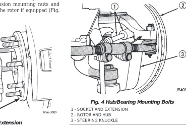
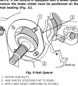
(5) Remove the hub/bearing nut (Fig. 3) and slide the hub/bearing off the spindle.On 3500 HD models the hub spindle shaft must removed (Fig. 4).
CAUTION: The hub/bearing nut can not be re-used.
INSTALLATION
(1) On models with all-wheel antilock system (ABS), check condition of tone wheel on hub/bearing. If teeth on wheel are damaged, hub/bearing assembly will have to be replaced (tone wheel is not serviced separately).
(2) Slide the hub/bearing onto the spindle.On 3500 HD slide the spindle stub shaft into the hub/bearing and tighten.
(3) Install the new hub/bearing nut and tighten to:
• 2500/3500: 380 N·m (280 ft lbs.)
(4) Install the rotor onto hub/bearing wheel studs. (5) Install the caliper adapter assembly (Refer to 5 - BRAKES/HYDRAULIC/MECHANICAL/DISC BRAKE CALIPERS - INSTALLATION), and tighten adapter bolts to:
• 2500/3500: 285 N·m (210 ft lbs.)
(6) Install the wheel and tire assembly and lower the vehicle, (Refer to 22 - TIRES/WHEELS/WHEELS - STANDARD PROCEDURE).
(7) Apply brakes several times to seat brake shoes. Be sure to obtain firm pedal before moving vehicle. Remover, Tie Rod End MB-990635
Puller Tie Rod C-3894-A
Fig. 3 Caliper Adapter Assembly 1 - HUB/BEARING
2 - SPINDLE
Fig. 4 SPINDLE STUB SHAFT 1 - Hub/Bearing
2 - Knuckle
3 - Spindle Stub Shaft
KNUCKLE
REMOVAL
(1) Raise and support the vehicle. (2) Remove the wheel and tire assembly.
(3) Remove the brake caliper and rotor, (Refer to 5 - BRAKES/HYDRAULIC/MECHANICAL/DISC BRAKE CALIPERS - REMOVAL).
(4) Remove the cotter pin and nut from the tie-rod end. Remove the tie rod end from the knuckle with Puller C-3894-A.
(5) Remove the cotter pins and nuts from the upper and lower ball joints. Separate upper ball joint from knuckle with remover MD-990635. Separate lower ball joint with remover C-4150A and remove knuckle.
INSTALLATION
(1) Position the knuckle on the ball joints and install the ball joint nuts.
(2) Tighten the upper ball joint nut to 81 N·m (60 ft. lbs.) and install cotter pin.
(3) Tighten the lower ball joint nut to:
• 149 N·m (110 ft. lbs.) Install the cotter pin. (4) Install the tie rod end on the steering knuckle and tighten the nut to 108 N·m (80 ft. lbs.). Install cotter pin.
(5) Install the brake rotor and caliper, (Refer to 5 -BRAKES/HYDRAULIC/MECHANICAL/DISC
BRAKE CALIPERS - INSTALLATION).
(6) Install wheel and tire assembly (Refer to 22 -TIRES/WHEELS/WHEELS - STANDARD PROCE-DURE).
(7) Remove support and lower vehicle.
LOWER BALL JOINT
DIAGNOSIS AND TESTING - LOWER BALL
JOINT
(1) Raise the front of the vehicle. Place safety floor stands under both lower suspension arms as far out-board as possible. Lower the vehicle to allow the stands to support some or all of the vehicle weight.
NOTE: The upper suspension arms must not be in maximum rebound position.
(2) Remove the tire and wheel assembly.
(3) Mount a dial indicator solidly under the lower suspension arm.
(4) Position indicator plunger against the bottom of the steering knuckle lower ball joint boss.
NOTE: The dial Indicator plunger must be perpen-dicular to the machined surface of the steering knuckle lower ball joint boss.
(5) Position a pry bar over the top of the upper suspension arm and under the pivot bar of the upper suspension arm. Pry down on the upper suspension arm and then zero the dial indicator.
(6) Reposition the pry bar under the upper suspen-sion arm and on top of the frame rail. Pry up on the upper suspension arm and record the dial indicator reading.
(7) If the travel exceeds 0.8 mm (0.030 in.) replace the suspension arm.
LOWER CONTROL ARM
REMOVAL
(1) Raise and support the vehicle. (2) Remove the tire and wheel assembly.
(3) Remove the brake caliper assembly and rotor, (Refer to 5 - BRAKES/HYDRAULIC/MECHANICAL/ ROTORS - REMOVAL).
(4) Remove the cotter pin and nut from the tie rod. Remove the tie rod end from the steering knuckle with Puller C-3894-A.
(5) Remove the stabilizer bar link from lower sus-pension arm.
(6) Support the lower suspension arm outboard end with jack. Place a jack under the arm in the front of the shock mount.
(7) Remove the cotter pin and nut from the lower ball joint. Separate the ball joint with Remover C-4150A.
(8) Remove the lower shock bolt from the suspen-sion arm.
(9) Lower the jack and suspension arm until spring tension is relieved. Remove spring and rubber isolator (Fig. 6).
(10) Remove bolts mounting suspension arm to crossmember and remove arm.
INSTALLATION
(1) Position the suspension arm on the crossmem-ber and install the bolts and nuts snug.
(2) Install the rubber isolator on top of the spring. Position the spring into upper spring seat.
(3) Raise the lower suspension arm with a jack and position the spring into the lower suspension arm mount.
(4) Install the lower shock bolt and tighten to 142 N·m (105 ft. lbs.).
(5) Install the steering knuckle on the lower ball joint. Install the lower ball joint nut and tighten to:
• 136 N·m (110 ft. lbs.) Install the lower ball joint cotter pin.
(6) Install the stabilizer bar link on the lower sus-pension arm. Install the grommet, retainer and nut and tighten to 37 N·m (27 ft. lbs.).
(7) Install the tie rod end on the steering knuckle and tighten nut to 108 N·m (80 ft. lbs.). Install cotter pin.
(8) Install the brake rotor and caliper assembly, (Refer to 5 - BRAKES/HYDRAULIC/MECHANICAL/ ROTORS - INSTALLATION).
(9) Install the tire and wheel assembly, (Refer to 22 - TIRES/WHEELS/WHEELS - STANDARD PRO-CEDURE).
(10) Remove the support and lower the vehicle. (11) Tighten the suspension arm crossmember nuts to 169 N·m (125 ft. lbs.).
SHOCK
DIAGNOSIS AND TESTING - SHOCK
A knocking or rattling noise from a shock absorber may be caused by movement between mounting bushings and metal brackets or attaching compo-nents. These noises can usually be stopped by tight-ening the attaching nuts. If the noise persists, inspect for damaged and worn bushings, and attach-ing components. Repair as necessary if any of these conditions exist.
A squeaking noise from the shock absorber may be caused by the hydraulic valving and may be intermit-tent. This condition is not repairable and the shock absorber must be replaced.
The shock absorbers are not refillable or adjust-able. If a malfunction occurs, the shock absorber must be replaced. To test a shock absorber, hold it in an upright position and force the piston in and out of the cylinder four or five times. The action throughout each stroke should be smooth and even.
The shock absorber bushings do not require any type of lubrication. Do not attempt to stop bushing noise by lubricating them. Grease and mineral oil-base lubricants will deteriorate the bushing.
REMOVAL
(1) Raise and support vehicle.
(2) Remove shock upper nut and remove retainer and grommet.
(3) Remove lower mounting bolt from suspension arm and remove shock (Fig. 5).
INSTALLATION
(1) Extend shock fully, install retainer and grom-met on top of shock absorber. Check gromgrom-mets and retainer for wear.
(2) Guide shock up through upper suspension arm bracket. Install top grommet, retainer and nut. Tighten nut to 54 N·m (40 ft. lbs.).
(3) Align bottom end of shock into lower suspen-sion arm and install mounting bolt. Tighten bolt to 142 N·m (105 ft. lbs.).
(4) Remove support and lower vehicle.
SPRING
REMOVAL
(1) Raise and support the vehicle. (2) Remove the tire and wheel assembly.
(3) Remove the brake caliper assembly and rotor, (Refer to 5 - BRAKES/HYDRAULIC/MECHANICAL/ ROTORS - REMOVAL).
(4) Remove the cotter pin and nut from the tie rod. Remove the tie rod end from the steering knuckle with Puller C-3894-A.
(5) Remove the stabilizer bar link from the lower suspension arm.
(6) Support the lower suspension arm outboard end with a jack. Place a jack under the arm in front of the shock mount.
(7) Remove the cotter pin and nut from the lower ball joint. Separate the ball joint with Remover C-4150A.
(8) Remove the lower shock bolt from the suspen-sion arm.
(9) Lower the jack and suspension arm until spring tension is relieved. Remove spring and rubber isolator (Fig. 6).
Fig. 5 Shock 1 - SHOCK
2 - JOUNCE BUMPER
INSTALLATION
(1) Install the rubber isolator on top of the spring. Position the spring into the upper spring seat.
(2) Raise the lower suspension arm with a jack and position the spring into the lower suspension arm mount.
(3) Install the lower shock bolt and tighten to 142 N·m (105 ft. lbs.).
(4) Install the steering knuckle on the lower ball joint. Install the lower ball joint nut and tighten to:
• 136 N·m (110 ft. lbs.) Install the lower ball joint cotter pin.
(5) Install the stabilizer bar link on the lower sus-pension arm. Install the grommet, retainer and nut and tighten to 37 N·m (27 ft. lbs.).
(6) Install the tie rod end on the steering knuckle and tighten nut to 108 N·m (80 ft. lbs.). Install cotter