Design, Construction and Application of
Synchronous Operation Machine Tool
Dr. Saif Imam
Asst. Professor, Dept. of Mechanical Engineering, College of Engineering, Jazan University, Jazan, K.S.A
ABSTRACT: A machine tool is a mechanical instrument used for shaping and machining metals or other materials, usually by cutting, boring, grinding or shearing. There are situations when the individual components of an assembled unit are finished by a sequence of processes which may include various cutting, grinding, plastic deformation, heat treatment etc. In order to manufacture such parts in large quantity, it is necessary to have one machine tool which can perform various manufacturing processes as opposed to distributing the operations to a series of many single purpose machine tools. With the objective of solving this commonly encountered problem, a synchronous operation machine tool design is proposed which will offer an appropriate substitute to the magnanimous collection of machines thereby reducing the time and complications involved in order to complete a task at hand.
KEYWORDS: Drilling, grinding, machine tool, power hacksaw, shaper
I. INTRODUCTION
Manufacturing industries are basically meant for production of useful goods and services at low cost. All the tasks in everyday lives have been made quicker due to technological advancements. However, this advancement also demands huge investments and expenditure. In view of this, every industry desires to achieve a high productivity rate while maintaining the quality and standard of the product at a low cost. The idea behind this project is to develop a conceptual machine tool which would be capable of performing different operations simultaneously while also being economically efficient.
Machining is one of the processes of manufacturing in which the specified shape to any work piece is imparted by removing the surplus material. Conventionally, this surplus material from the workpiece is removed in the form of chips by interfacing the workpiece with an appropriate tool. The process of chip formation during metal cutting is affected by relative rotatory or translatory motion between a tool and the workpiece achieved with the aid of a device called machine tool.
A machine tool is a machine for shaping or machining metal or other materials, usually by cutting, boring, grinding, shearing, or other forms of deformation. Machine tools usually employ some types of tools that do the cutting or shaping. All machine tools have a means of constraining the workpiece and as well as providing a guided movement of the different parts of the machine. Thus, the relative movement between the workpiece and the cutting tool which is called the tool-path is controlled or constrained by the machine to at least some extent, rather than being entirely offhand or freehand.
II. RELATEDWORK
The survey and review of the literature regarding the evolution of multifunctional machines tools are chronologically listed below:
Elly Whitney in the year 1827 from United States of America developed the milling machine, which utilized a rotary cutter with multiple edges. Initially, it was mainly used to machine flat surfaces. This was later modified and expanded to include its application to two and three dimensional surfaces [1]. D. Chaitanya designed and developed a multipurpose human powered machine for operations like cutting, grinding etc. However, owing to certain special attachments, this machine had the dual advantage of being operated by electric power as and when required. The design proved to be ideal, especially in the developing nations as it did not require electricity and could be built using metal base, chain, pulley, rubber belt, grinding wheel, saw, bearing, foot pedal, electric motor, and chain socket [2]. S.G.Bahaley et al. designed and fabricated a pedal powered multipurpose machine. This was basically a human powered machine which was developed for the purpose of lifting water to a height 10 meter and generated 14 Volt, 4 ampere of electricity in the most effective way [3].Linxu et. al. designed and developed an automatically reciprocating pedal powered electricity generator (ARPPEG) meant to be useful for the management and control over harvesting the kinetic energy, electricity generation, electric storage and the output of electricity. According to the operation testing results, this system was found to be effective in power generation. In view of the simple structure and low costs of this system, the application of ARPPEG designed opened a new path for saving energy and helping build a new energy society [4]. Dr. Toshimichi Moriwaki in his paper wrote about the trends in the machine tool technologies that were surveyed from the view point of high speed and high performance machine tools, combined multifunctional machine tools, ultra precision machine tools and advanced and intelligent control technologies [5]. Dr. Toshimichi Moriwaki stated that the earliest form of boring machine was developed by John Wilkinson and the lathe was developed by Henry Maudslay, which were typical examples of these machines. The basic configuration of a lathe or turning machine remained mostly the same for a long time. Later, over the years, in order to increase the productivity of the turning machine, the multi-axis automatic turning machine was developed, which could perform several turning operations simultaneously on a single machine equipped with multiple spindles. As simultaneous multi-axis control became possible with the advances in NC technology, turning machine with two turrets was developed which could simultaneously cut the work with two cutting tools [6]. Frankfurt Main in his paper stated that the crisis is over, but selling machinery remains a tough business. Machine tools now-a- days have to be veritable “jack of all trades”, able to handle all kinds of materials, to manage without any process materials as far as possible, and be capable of adapting to new job profiles with maximized flexibility. Two highly respected experts on machining and forming from Dortmund and Chemnitz report on what’s in store for machine tool manufacturers and users. Multi-purpose machines are the declarations of independence. The trend towards the kind of multi-purpose machining centers that are able to cost efficiently handle a broad portfolio of products with small batch sizes accelerated significantly during the crisis. “With a multi-purpose machine, you’re less dependent on particular products and sectors” [7]. Kevin et al. design and developed manual multifunctional portable machine which can be used to perform various operation like drilling, milling, grinding of small work pieces precisely [8]. Sharad et al. Designed and developed a wooden conceptual model multi function machine meant for production of useful goods and services at low production cost, machinery cost and low inventory cost [9]. The fundamental functions of machine tools are to transform the raw materials with given mechanical properties to the finished parts with required geometry, dimensions and surface quality. As the demands are increasing to produce parts with higher quality at reduced cost, the machine tools are required to have higher machining accuracy and speed. In recent years, the demands are also increasing to machine difficult to cut materials and parts with complex geometry. As the production lot size becomes smaller, a single part with complicated geometry has to be machined without a trial cut. In order to meet such requirements, the machine tools are expected to have multiple functions with modular and reconfigurable design architectures [10, 11, and 12].
III.DESIGNAPPROACHANDMETHODOLOGY
particular operation. The designed machine can be used for processes like cutting of several materials such as wood, masonry, plastic, metals etc.
There are situations when many of the parts are finished by a sequence of processes, like cutting, grinding, plastic deformation etc. In order to manufacture any automotive parts or any engine assembly parts in large quantity, it is necessary to have one machine tool which can perform various manufacturing processes as opposed to distributing the operations to a series of many single purpose machine tools. The synchronous machine tool will offer an appropriate substitute to a magnanimous collection of machines thereby reducing the time and complication involved in order to complete the task at hand.
The synchronous operation machine tool as shown in fig. 1 is designed for the college of engineering machine shop with special emphasis on its selection of the appropriate power hacksaw blade, grinding wheel, shaper tool and drill bit. The designed machine was tested for different work pieces to find out whether it serves the purpose for which it was designed. The important parts of the designed synchronous machine includes a motor, which drives all the units, hacksaw blade fitted in a frame, steel frame, set of shafts which hold pulley, bearings which support the shaft, pulley for transmission of power, belt etc. Based on the principles of design and formulas from the design handbook, the size and the material of each component required under the situation of operation was calculated and selected. The methodology covers the selection of material and its size for its parts discussed above according to the situation under which the setup will be operated.
IV.DESIGNCALCULATIONANDFORMULATION
d1 = 50mm d2 = 230mm d3 = 230mm d4 = 270mm d5 = 100mm
Where, d1- diameter of pulley of motor, d2- diameter of small pulley for pair 2, d3 diameter of small pulley for pair 2, d4- diameter of large shaft pulley for pair 2, d5- diameter of shaft pulley for pair 1.
Power of Motor and Torque available at different points
P = 4HP = 4 × 745 = 2980Watt
The power obtained from the motor is shared equally by two different pair of machines, namely pair 1 and pair 2. Pair 1 belongs to the combination of drilling and grinding whereas pair 2 belongs to the combination of shaper and the hacksaw. So, the power for each pair available is 2HP.The shaft and pulley arrangement of the same is shown in fig. 2.
P = 2HP = 2 × 745 = 1490Watt P = 1492W = 1.492KW
Selection of Bevel Gear
A bevel gear is used to change the direction of drive in a gear system by 90 degrees. In this case a Milter gear is used. Milter gears are mating bevel gears with equal numbers of teeth and with axes at right angles. The number of teeth of Milter gear selected is 28. A Straight bevel gears used have conical pitch surface and teeth are straight and tapering towards apex. For design simplification it is assumed that there is no power loss in changing the direction of drive. The material for the bevel gear selected is cast iron.
Calculation of Grinding Wheel Velocity
Grinding wheel speed is referred to as Surface meter per minute (SMPM). It means the distance in meter any one abrasive grain on the peripheral surface of a grinding wheel travels in 1 minute.
SMPM =π× × (1) Where, D= diameter in meter, N= rotational speed in RPM
Calculation of Cutting Speed of Shaper
V = ( ) m/min (2)
V= cutting speed, m/min, N= no. of complete strokes per min, L= length of stroke, m, M= ratio of time taken in return stroke to the time taken in cutting stroke.
V =125 × 90(1 + 0.45)
1000 m/ min V = 16.31 m/min
Figure 1 shows the assembled synchronous operation machine tool showing the Scotch Yoke mechanism on pair 2 with power hacksaw on one of its side and shaper tool on the other side. Pair 1 of grinding and drilling is on the backside of the frame. The whole units of this m/c tool are fixed on the steel frame. Figure 2 shows the schematic arrangement of all shaft and pulley. The name and dimensions of the pulley is also mentioned.
Selection of Belt
As per the design handbook, the prescribed belt type for the given distance between the two pulleys is V-belt. So, all the belts selected in this project are V-Belt.
Selection Of Shaft Material and Calculation of its Size
S.f (Factor of Safety) selected as 2 σ = 34 N m⁄ τ σ
×σ
.
(3)
τ σ
× . ⁄
G =E 2=
200 × 10
2 = 100 × 10 N m⁄
τ
× /
π
τ = ×
×π× ; D = ×
×π×τ ; D = 31.03mm
Design of shaft is based on strength. In this method, design is carried out so that stress at any location of the shaft should not exceed the material yield stress. However, no consideration for shaft deflection and shaft twist is included.
Figure 2 shows schematic representation of shaft and pulley arrangement
Figure 1 shows the schematic view of the synchronous operation m/c operation tool
N2
N1 N3
N4 N5
270 23
0
50
Carbon Steel SAE 1045 is selected as shaft material. It serves the required property the shaft which also includes corrosion resistant property. Standard Dia. of the shaft available in market is 20 mm for pair 1 and 30 mm for pair.
Selection of Bearing
Two sets of FYH Ball bearing are used to support and carry shafts of 20 mm and 30 mm respectively. One for pair 1 and other for pair 2. The balls of the bearing are made up of 52100 chrome steel.
Design of Frame
The frame on which the whole components of machine are mounted is termed as table. The material selected for this purpose is steel and this frame is made up of steel angles of 4 mm thickness. The height of the table is taken as 1300 mm whereas length and width as 1000 mm.
V. CONSTRUCTIONALDETAILS
The heart of the entire unit is a motor which supplies the required power to these units. A 3 KW, 220 Volts, 3 phase, 4 HP motor is used for this purpose. The power of motor is shared by two different pair of units. The motor is located in front of the frame at a distance of 320 mm from right end of its column. Motor is attached with a twin groove 50mm small pulley. One part of the power is shared by the grinding and drilling unit which is on the right hand side of the motor as shown in fig. 3 and is referred to as pair 1. The other part of power is shared by shaper and the hacksaw which lie on the left side of the motor which will be referred as pair 2 and shown in fig. 4
Pair 1
The small twin pulley shown in fig. 4 is attached to the motor is coupled with another pulley of 100mm which holds a shaft on pair 1 with the help of V-belt. The shaft in itself is supported by a set of ball bearings. One side of the shaft is attached with a grinding wheel and the other side is attached with a set of straight bevel gears. The driver bevel gear is in vertical position and is attached with the shaft and driven one in horizontal position is attached to the spindle of the drilling unit. The driven bevel gear holds a vertical drilling machine unit. Bevel gears are used to change the direction of drive by 90 degrees for running vertical drill. Both the gear used is straight bevel gear with 28 teeth with equal diameter.
Figure 4 Schematic view of the m/c tool showing various components.
Pair 2
The same small pulley attached with the motor is coupled with a medium size pulley which in turns coupled with a large pulley which holds and run a shaft supported with a set of ball bearings. The other side of the shaft is fixed with a disc. The disc is pinned with a slotted lever. This arrangement is for employment of scotch yoke mechanism as shown in fig. 3 for converting the rotary motion of the shaft into reciprocating motion of an arm attached to the slotted lever. This arm serves as a ram for the shaping machine and carries a shaper tool to its one end. Disc is pinned at distance of 500mm from the right column on the side opposite to motor location. The other side of the arm is attached with the hacksaw frame with a blade. Both the strokes, forward as well as backward are utilized for the cutting operation. In this case Scotch Yoke mechanism is utilized. The design is based on the requirement of the project which is for the use of machine tool for cutting light jobs in the college machine shop.
VI.EXPERIMENTALDETAILS
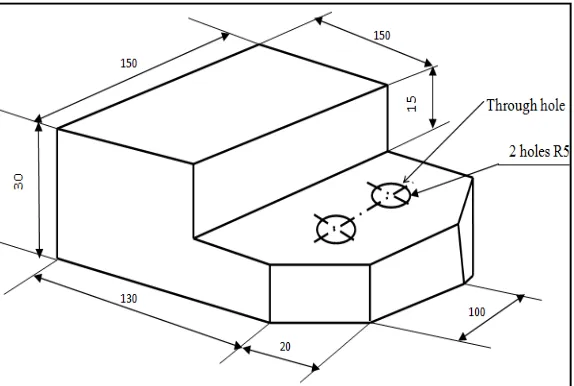
The machine tool was tested on different engineering materials mainly mild steel, aluminium and plastic, brass etc. The tests were conducted in normal conditions of temperature and pressure. In the phase of experimental tests a block of 150mm X 150mm X 30mm of the mentioned materials was taken. The objective was to transform the above mentioned block into the shape shown in fig. 5. The machines that could be involved in achieving the desired shape will be shaper, power hacksaw, drill and a grinder. But, instead of utilizing the variety of different machine we used the designed synchronous operation machine tool.
Figure 5 shows shape of different material obtained from this m/c tool
VII. RESULTANDDISCUSSION
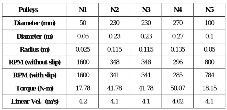
Table 1 shows calculation of important parameters
As far as grinding unit is concerned, for the size of 120 mm and with the speed of 784 RPM, the SMPM calculated is 295. This SMPM directly fits for aluminium in our case. For brass, plastic, steel and cast iron, either we have to change the grinding wheel diameter or achieve the required SMPM by engaging or disengaging the other pulley.
Number of strokes per minute for power hacksaw unit is 45 and it fits well for brass, cast iron and steel alloy for 20 25 cm blade length. If the other unit is disengaged then it can also be used for brass, cast iron and steel alloy for 10 cm-15 cm blade size.
Shaper unit fits well for roughing cut for bronze and cast iron when high speed tool steel is selected, and finishing cut for bronze and cast iron when carbon tool steel is selected. In order to cover aluminium and brass higher cutting speed is needed which can be attained by disengaging the other unit.
VIII. CONCLUSIONS
From the test carried out, the following conclusions were made. It has been established after the completion of the project that this project offers a simple low capital machine tool for the machine shop producing a job that follows a particular sequence of operation. The capital cost involved in the construction of a machine tool is much lower to that of a commercially available other single unit machine tool.
Also, from the project carried out, the simple and inexpensive synchronous operation machine tool was designed and constructed using locally sourced materials. The machine is tested for different materials mainly wood, mild steel, aluminium and plastic. The synchronous operation machine tool constructed was tested for efficiency under experimental conditions and it was found to be effective for the variety of jobs involving different materials mentioned above.
Pulleys N1 N2 N3 N4 N5
Diameter (mm) 50 230 230 270 100
Diameter (m) 0.05 0.23 0.23 0.27 0.1
Radius (m) 0.025 0.115 0.115 0.135 0.05
RPM (without slip) 1600 348 348 296 800
RPM (with slip) 1600 341 341 285 784
Torque (N-m) 17.78 41.78 41.78 50.07 18.15
Table 2 shows recommended speed for drilling, grinding, shaper and power hacksaw
IX.ACKNOWLEDGEMENT
I wish to express my gratitude to all those who provided help and cooperation in various ways at the different stages for this research project. Also, I would like to express my sincere appreciation to Dean of the College of Engineering Dr. Jabril Ahmed Khamaj, Head of Mechanical Engineering Department Dr. Ali Saeid Alshahrany, my friend Dr. Zahir Hasan and Er. Abdul Aziz.
Recommended Operating Speed for Drill (RPM)
Recommended Operating Speed for Power Hacksaw in strokes/min.
Drill bit Diameter
(mm)
Wood Acrylic Brass Aluminium Steel
Material
Speed in strokes per min
1.5-4.5 3000 2500 3000 3000 3000 Blade Size
6.3-9.3
1500-3000 2000 1200 2500 1000 10-15 cm. 20-25 cm.
11-15.5
750-1500 1500 750 1500 600 Aluminium 135 65
17-25 500-750 NR 400 1000 350 Brass 135 65
Recommended Operating Speed for Grinding (SMPM) Bronze 90 45
Material Surface Meter Per Min. Cast Iron 90 45
Aluminium 304 Copper 135 65
Brass 122
Steel Alloy 90 45
Plastic 122-152
All Steel 76-91
Cast Iron 61
Shaper cutting speed in Meter per Minute
Material to be shaped
High speed
tool steel Carbon tool steel
Roughing Cut Finishing Cut Roughing Cut Finishing Cut
Aluminium 46 Max. safe speed 30.5 45.7
Brass 46 Max. safe speed 30.5 45.7
Bronze 18 30.5 9 15.2
REFERENCES
[1] R. Woodbury, “Studies in the History of Machine Tools”, MIT Press, 1972.
[2] D. Chaithanya, “A Research on Multi Purpose Machine”, International Journal for Technological Research in Engineering, Vol.1, Issue.1, ISSN: 2347-4718, 2013.
[3] S. Bahaley, A. Awate, A. Saharkar, “Performance Analysis of Pedal Powered Multipurpose Machine”, International Journal of Engineering Research and Development (IJERD), Vol.1, Issue.5, ISSN: 2278-0181, 2012.
[4] Linxu, W. Bai, R. Jingyu, Q. Li., “Design and Implementation of the Reciprocating Pedal Powered Electricity Generating Device”, Advanced Materials Research ,Vol.282-283 ,pp 735-738, 2011.
[5] T. Moriwaki, “Trends in Recent Machine Tool Technologies”, NTN Technical Review No.74, 2006.
[6] T. Moriwaki, “Multi-functional machine tool”, CIRP Annals - Manufacturing Technology DOI: 10.1016/j.cirp., 2008. [7] F. Main, “Multi-purpose machines ensure enhanced”, 2011.
[8] K. Patel, N. Kumar, S. Agrawal, “Design and development of a manual Multifunctional portable machine” International Journal of innovations in Engineering and technology (IJIET) Vol.2 Issue 2, ISSN: 2319-1058 page 157-163, 2013.
[9] S. Srivastava, S. Shivam, C. Khatri, “Multi-Function Operating Machine: A Conceptual Model”, IOSR Journal of Mechanical and Civil Engineering (IOSR-JMCE) e-ISSN: 2278-1684, p-ISSN: 2320-334X, Volume 11, Issue 3 Ver. III , PP 69-75, 2014.
[10] F. Jovane, Y. Koren, C.R.Boer, “Present and Future of Flexible Automation: Towards New Paradigm”, Annals of the CIRP 52/2:543–560, 2003.
[11] Y. Koren, U. Heisel, F. Jovane , T. Moriwaki, G. Pritschow, G. Ulsoy, H. VanBrussel, “Reconfigurable Manufacturing Systems”, Annals of the CIRP 48(2):527–540, 1999.
[12] R.G.Landers, HB. Min, Y. Koren, “Reconfigurable Machine Tools”, Annals of the CIRP 50(1):269–274, 2001.
BIOGRAPHY