This work was supported by the IBM Fellowship, the Center for Advanced Computing & Communication at North Carolina State University and NSF Grant NCR-9410227.
Multiuser Detection and Channel Estimation
for Flat Rayleigh Fading Mobile Radio CDMA Channels
by
Peter Hsin-Yu Wu Alexandra Duel-Hallen
Department of Electrical and Computer Engineering
Box 7911, North Carolina State University
Raleigh, NC 27695
Abstract
We compare the performance of suboptimal multiuser detectors for rapidly time-varying
fading channels. Disjoint Kalman filters are incorporated in the detector structure to obtain phase
and amplitude estimates for coherent detection and multi-access interference cancellation. We also
evaluate performance of several multiuser detectors which do not require channel estimation. Our
results indicate that relative gains of various detectors depend on the maximum Doppler frequency
since the estimation error grows as the maximum Doppler frequency increases. In contrast to the
case when the Doppler shift is small and the channel can be accurately estimated, the more complex
detectors (two-stage and decision-feedback) do not provide significant performance gain over the
simpler decorrelator when estimation errors are large. For both classes of detectors (with and
without channel estimation), the decorrelator outperforms other considered schemes for high
signal-to-noise ratios in fast fading environment and asymptotically approaches the performance of
the single user system.
Several fading channel models are considered. We prove that a realistic fading channel can
be approximated by the second order autoregressive process (AR) process and discuss coefficient
adjustment for the AR model. It is also shown that error bursts often occur due to the "reversal
phenomenon" when the Kalman filter is used in the decision-directed mode. We demonstrate that
differential encoding remedies this problem.
I. Introduction
Multiuser detection has the potential to reduce the Multi-Access Interference (MAI) and solve
the near-far problem in the reverse link of a Code Division Multiple Access (CDMA) channel [1].
Since the optimal multiuser detector requires much higher complexity than the conventional
detector, recent studies focus on the suboptimal multiuser detection schemes with reasonable
complexity. Among these schemes are the linear decorrelator [2], the multi-stage detector [3], the
decision-feedback detector (DF) [4], the successive interference cancellation scheme (SIC) [5], and
the parallel interference cancellation scheme (PIC) [6-7].
The performance of these suboptimal detectors has been extensively studied for the Additive
White Gaussian Noise (AWGN) channels, and recent studies address on their performance for
fading channels. The analysis of multiuser detectors for fading channels is often conducted under
the ideal assumption of perfect channel estimation [2-10]. The assumption is not valid in practice
due to the difficulties of estimating rapidly time-varying channels in mobile radio systems.
Therefore, the performance of multiuser detection algorithms should be assessed under more
realistic conditions. In [11-12] the performance of the decorrelator was evaluated in the presence
of the channel mismatch, and in [13-15] the two-stage (2S) and the DF were considered.
Imperfect channel estimation degrades performance of multiuser detectors since many multiuser
detectors require channel estimates to cancel the MAI and/or to perform coherent reception. The
main purpose of this paper is to compare robustness of multiuser detectors with channel estimation
for realistic rapidly time-varying flat Rayleigh fading channels.
The performance comparison can be summarized as follows. We found that when the fading
channel is perfectly estimated (e.g., for very slow fading), the more complex detectors, such as the
2S and the DF, can achieve the single user bound and are near-far resistant [14]. However, the
simpler schemes, such as the SIC and the PIC, are not suitable for the high bandwidth efficient
channels, and should be applied to systems with relatively low cross-correlations. When the
channel mismatch is present due to fast fading, the performance of the coherent multiuser
detectors--the decorrelator, the 2S, and the DF, becomes comparable. As the Doppler frequency
increases, the performance gain of the 2S and the DF over the decorrelator decreases, and is limited
to lower SNR region. The performance degradation of the 2S and the DF is due to the channel
estimation errors of all the users. The decorrelator, with less complexity than the 2S and the DF,
has a lower error floor, which is identical to the error floor of the single user system. The near-far
resistance is still preserved in the decorrelator, but not in the 2S and the DF. For noncoherent
multiuser detectors (the decorrelator, the SIC, and the PIC), the decorrelator outperforms the other
methods, and retains the near-far resistant property. These results indicate that the decorrelator is
To implement multiuser detectors for rapidly varying fading channels, we studied reliable
channel estimation algorithms. It was first mentioned in [16] that the estimation of channel
coefficients is equivalent to carrier phase tracking, and more work [17-18] was devoted to applying
the Kalman filter to channel estimation. In most of these studies the fading channel was modeled
as an auto-regressive (AR) process in order to apply the Kalman filter. In this paper, in addition to
the AR model, we also consider a more realistic channel model--Jakes model [19] with
modification of [20]. We verify that a simple second order AR process (AR2) can approximate the
Jakes model and can be used as a hypermodel embedded into the Kalman filter. It was observed in
[21] that the spectral peak frequency of the AR2 process should be adjusted by a factor of 2
from the maximum Doppler frequency [21]. This adjustment is justified in this paper. This simple
AR hypermodel for the realistic fading channel reduces the complexity of the Kalman filter
implementation and makes computationally tractable analysis feasible.
Regarding the operation of the Kalman filter, we showed in [22] that the Kalman filter
operating in the decision-directed mode would produce the channel estimates that often have about
180-degree phase shift relative to the channel coefficients. We term this behavior "the reversal
phenomenon." The phase shift causes long burst of errors and results in a very high BER (on the
order of 10-1). In [22] and this paper, we derive the cause of the reversal phenomenon. We also
show that differential encoding eliminates long burst of errors, and consider both coherent or
noncoherent detection of the differentially encoded data for several multiuser detectors.
Combinations of Kalman filters and multiuser detectors were also studied previously. In
[23-24], it was shown that a multiuser detector and a channel estimator can be decoupled, and a
joint Kalman filter was shown to be the optimal channel estimator. In [25], it was shown that the
Kalman filter can be configured to estimate all the users' channel coefficient jointly or disjointedly.
We adopt simpler disjoint estimation in our work. With the AR channel model, the Bit Error Rate
(BER) analysis of the decorrelator, the DF, and the two-stage detector (2S) with the disjoint
Kalman channel estimators can be found in [12-14, 22]. These results were for Binary Phase Shift
Keying (BPSK) modulation, and are extended to the differentially encoded data in this paper.
The paper is organized as follows: Section II reviews the multiuser detectors to be compared.
Section III is devoted to the issues of channel estimation using the Kalman filter. It includes the
construction of the hypermodel for the AR process and the modified Jakes fading model, the
reversal phenomenon, and other implementation issues. In Section IV, we analyze the BERs of
multiuser detectors for perfect channel estimation and with the channel mismatch using the unified
analysis. In Section V, several numerical examples are presented, and the analytical results are
verified using simulations. Finally, we conclude our work and discuss future directions in Section
II. Synchronous CDMA System Model and Multiuser Detectors
In this section, we review the mathematical model of a synchronous CDMA system and the
structures of the considered multiuser detectors.
A. Synchronous CDMA system
Consider N users which transmit simultaneously using different signature waveforms over
independent flat Rayleigh fading channels. Assuming that the signals of all uses arrive at the
receiver at the same time, i.e., they are synchronized, the received signal, in complex baseband
notation, is
r(t)=
i=0 ∞
∑
n=1
N
∑
2Ebn T Cn(i) bn(i) sn(t−iT )+n(t),where
i: the sampling time index;
n: the user index; n=1, ..., N;
Ebn: the bit energy of the n-th user;
T: symbol interval;
Cn(i): the fading coefficient for the n-th user. For Rayleigh fading channel, Cn(i) has zero
mean and unity variance, i.e., E{Cn(i)}=0 and E(|Cn|2)=1 or E(|CnI|2)=E(|CnQ|2)=1/2
(Superscripts I and Q denote the in-phase and quadrature components);
bn(i): the information bit of the n-th user at the i-th sampling instance; bn(i)∈{+1,-1};
sn(t): the signature waveform of the n-th user; 0
T ∫ sn(t)sn
*
(t)dt=T ;
n(t): the complex additive white Gaussian noise with zero mean and variance N0.
The received signal is fed to a bank of matched filters, where each matched filter correlates each
individual user's signature waveform. After normalization, the output of the matched filter bank
(MFB) at the k-th sampling instance can be represented by the column vector y of length N:
y(k)=RW(k)b(k)+n(k), (1)
R: the signature cross-correlation matrix (NxN); Rl,m =(1 T ) sl(t)sm*
(t)dt
0
T
∫ (l, m =1,
..., N);
W(k): the channel gain matrix (diagonal, NxN)); Wn,n(k)= EbnCn(k)= Ebn|Cn
(k)|exp(-jθn(k)) (n =1, ..., N);
b(k): the vector of information bits of N users (Nx1); bn(k)=bn(k) (n =1,...,N);
n(k): the complex Gaussian noise vector (Nx1); nl(k)=(1 2T ) n(t)sl
*
(t−kT )dt
kT
( k+1)T
∫
(l =1, ..., N). The noise vector has the covariance matrix E(n*n)=R N
0 (* denotes
B. Multiuser detectors
(1) The conventional detector
In the conventional detector the decision for user n is made by using the output of the
matched filter directly, i.e., ˆbn(k)=sgn{ Re[yn(k) ˆCn*(k)] }, where ˆCn(k) is the channel estimate of
user n.
(2) The decorrelator
In the decorrelator, the matrix filter R-1 is applied to (1) [2]. The output of the decorrelator is
z(k) = R-1y(k) = W(k)b(k) + v(k), (2)
where the noise vector v(k) = R-1n(k), and the decision for the n-th user is
ˆ
bn(k)=sgn(Re[zn(k) ˆCn*
(k)]).
(3) The two-stage detector
The two-stage detector considered here uses the decorrelator as the first stage [3]. In the first
stage, the tentative hard decisions are formed, and in the second stage they are used to reconstruct
the MAI for cancellation. The final decision is made after canceling the MAI from the MFB (1).
The final decision for the n-th user is ˜bn(k)=sgn{[yn(k)−M ˆAIn(k)] ˆCn*
(k)}, where M ˆAIn is the
reconstructed MAI for user n, defined by M ˆAIn(k)=
i=1,i≠n N
∑ Rn,iWˆ i,i(k) ˆbi(k) ( ˆWi,i(k)= Ebi ˆCi(k)).
(4) The decision-feedback detector
The operation of the DF was described in detail in [4]. In this paper, for efficient
implementation of the DF and the Kalman filter, we consider the noise-canceling version of the DF
[4]. Since the Kalman filters use the outputs of the decorrelator (see section III), the matrix filter is
applied first as in (2), and the enhanced noise of each user is estimated and canceled successively.
The performance of the noise-canceling DF was shown to be identical to the original DF [4].
The DF first sorts the MFB outputs in the descending signal strength order. The sorted
MFB output vector is ys(k)=Rs(k)Ws(k)bs(k)+ns(k), where the superscript s denotes the
sorted result, and |Ws
1,1(k) |≥ |Ws2,2(k) | ≥ ... ≥ |WsN,N(k) |. By Cholesky factorization, the inverse
of the autocorrelation matrix Rs(k) is given by [Rs(k)]-1=[FS(k)]-1 [FS(k)T]-1, and the sorted
decorrelator output (2) can be rewritten as
zs(k)=Ws(k) bs(k) + [Fs(k)]−1 ˜ns(k) , (3)
where ˜ns(k)=[Fs(k)T]−1ns(k) . For the n-th strongest user, the noise term depends on n-1 noise
components that can be estimated using the decisions of n-1 stronger users. The decision of n-th
user is given by ˆbns
(k)=sgn{Re[ ˜zns
(k) ˆCns*
(k)]}, where ˜zns
(k)=zns
(k)−
i=1
n−1
∑
[
[Fs(k)}−1]]
n,inˆi s
(k)
and the noise estimate is ˆni
s
(k)=[Fs(k)]i,i {˜zi s
(5) The successive interference cancellation (SIC) schemes
The basic concept of the SIC [5-6] is similar to that of the DF where the users are
demodulated successively according to their strengths. Unlike the DF, it does not require any
matrix inversion or factorization. In reconstruction of the MAI in the SIC detector, several
different signals can be used, namely, a soft decision, a hard decision, or a matched filter output.
We denote these three types by SIC-SD, SIC-HD and SIC-MF, respectively. In [5], the SIC-SD
with BPSK modulation was studied. In addition, the performance of the SIC was evaluated for
the IS-95 standard. It was shown that this detector can significantly outperform the conventional
detector for this channel.
These SIC schemes can be implemented in discrete time as follows:
SIC-SD Initially, set M=N (the number of users). At each iteration, the remaining M users are
sorted so that d1
s
(k) ≥ d2
s
(k) ≥ ... ≥ dM s
(k) , where di
s
(k) is the decision variable of the i-th
strongest user defined by dis(k)=Re[e−jθi
s( k )
yis(k)]. The phase term e−jθi s( k )
is determined as
e−jθis( k ) = Wi,i
s *
(k)
Wi,i s
(k) . Make a decision for the strongest user among M remaining sorted users using
d1
s
(k): ˆb1
s
(k)=sgn{d1
s
(k)}. Reconstruct the MAI for other remaining users due to the strongest user, i.e., M ˆAIi =Ri,1s ejθ1s( k ) d
1
s
(k) (i=2, ..., M) and subtract it from the signals of other
remaining users: yis(k)←yis(k)−M ˆAIi(k) (i=2, ..., M). Then set M←M−1 and repeat the loop
until every user is demodulated.
Note that the decision variable of the strongest user is actually equal to
d1
s
(k)= Eb1s C1
s
(k) R1,1
s
b1
s
(k) + MAI + background noise. The decision variable only contains
the amplitude information of the strongest user, and no phase information is given. Therefore, the
reconstruction of the MAI requires the phase information in addition to the cross-correlation
values.
SIC-HD The SIC-HD is identical to the SIC-SD except that the hard decision {+1, -1} is used
for MAI construction. The hard decision contains no information of the phase and the amplitude,
therefore, the reconstruction of the MAI requires the estimates of both. The algorithm described
above for the SIC-SD is modified as follows: reconstruct the MAI using
M ˆAIi =Ri,1s W1,1s (k) ˆb1s(k) (i=2, ..., M).
SIC-MF The SIC-MF uses the matched filter outputs in sorting the users and in reconstructing
the MAI. The following two modifications of the algorithm for SIC-SD are implemented. First, in
sorting the users, use y1
s
(k) ≥ y2
s
(k) ≥ ... ≥ yM s
(k) . (In the first iteration, M=N, and the
actual matched filter outputs are used, yis(k)= yi(k), i=1, ..., N). Second, to reconstruct the
Note that in this algorithm channel estimation can be completely avoided if noncoherent
(e.g., DPSK) detection is used. For the SIC-SD and the SIC-HD, even with noncoherent
demodulation, channel estimation is still required for MAI reconstruction.
(6) The parallel interference cancellation (PIC) scheme
The PIC considered here is identical to the approximate decorrelator discussed in [7]. The
PIC directly uses the outputs of the matched filter bank to reconstruct the MAI for all users in a
parallel fashion and therefore does not require ordering of users as in the DF and the SIC. With
the definition R=I+L (I is NxN identity matrix), the signal after MAI cancellation in the PIC is
given by [26]
˜y(k)=R y(k)˜ =RW(k)b(k)ˆ + ˆn(k), (4)
where ˜R=I−L , ˆR=R R, and ˆn(k)˜ =R n(k). The matrix filter ˜˜ R is the first order
approximation of R−1 =I−L+L2−L3+...[7].
III. Channel Estimation
Several of the multiuser detectors considered in Section II require fading channel estimation
for reconstruction of MAI. In general, channel estimation is an important issue in coherent
detection. For the mobile fading channel, the tracking of the phase is difficult to achieve with the
traditional Phase Locked Loop (PLL) [18]. It was shown in [18] that the slow convergence
problem of the PLL ("hang-up effect") can be overcome by using a Kalman filter, which estimates
the in-phase and the quadrature components of the channel coefficients. When a fading channel
obeys the Gauss-Markov model, the Kalman filter is the MMSE estimator [27]. The use of the
Kalman filter requires the statistical knowledge of the fading channel and since the statistical
information of the fading channel is available, the Kalman filter has recently been adopted for
estimating a rapid time-varying channel [21]. The statistical knowledge leads to the construction of
the hypermodel, which is embedded in the Kalman filter. In this section, we first briefly introduce
the Kalman filter, and show how to construct the hypermodel for the realistic fading channel using
a AR2 process. Finally, we discuss the practical considerations regarding the use of the Kalman
filter.
A. The Kalman filter
The hypermodel used in the Kalman filter consists of two parts. The first part describes the
process to be estimated, and is defined by the Gauss-Markov model. The second part is the model
of the measurement process. They can be expressed by the following state space equations [27],
X(k+1)=A(k) X(k)+G(k) W(k) (5)
z(k)=HT(k)X(k)+V(k) (6)
where the column vector X(k) is a state variable, the column vectors W(k) and z(k) are the input
process or the measurement process, which is corrupted by the observation noise V(k). The
matrices A(k), G(k), and H(k) contain the parameters of the system dynamics.
Once the hypermodel ((5) and (6)) is acquired, the MMSE estimate of the state variable can
be generated recursively by the following equations [27]:
M(k)= Σ(k) H(k) [HT(k) Σ(k) H(k)+P(k)]−1, (7)
Kalman filter gain: K(k)=A(k) M(k), (8)
Prediction (Kalman Filter): ˆX(k+1)=[A(k)−K(k) HT(k)] ˆX(k)+K(k) z(k), (9)
Error Covariance:Σ(k+1)=A(k) [Σ(k)−M(k) HT(k) Σ(k)] AT(k)+G(k) Q(k) GT(k),
(Riccati equation) (10)
where the matrices P(k), Q(k), and Σ(k) are covariance matrices of the observation noise, the input
signal, and the estimation error, respectively. They are defined by
P(k)= E{V(k)VT(k)}, (11)
Q(k)=E{W(k)WT(k)}, (12)
Σ(k)=E{[X(k)−X(k)][X(k)ˆ −X(k)]ˆ TZ(k−1)}, Z(k-1)={z(0), z(1),..., z(k-1)} (13)
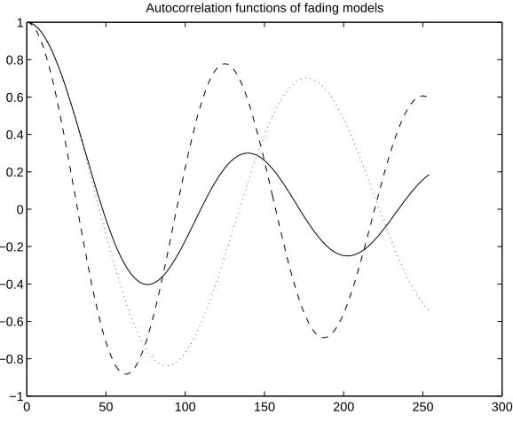
B. Fading channel models and selection of the hypermodel for the Kalman filter
It is well known that a Rayleigh fading process C(t) can be characterized by its
autocorrelation function or its power spectrum density [19]:
The autocorrelation function:
Φ(τ)=J0(2π fdτ) , (14)
The power spectrum density:
Ψ( f )= 1
π fd
1
1−
(
f fd)
2, f ≤ fd, (Baseband) (15)
where J0(•) is the Bessel function of the zero-th kind, and fd is the maximum Doppler frequency
in hertz. When using the Kalman filter to estimate a fading process, equations (14) and (15) can be
utilized in constructing the Gauss-Markov model (5) in the hypermodel.
(1) The modified Jakes model
In [19], Jakes proposed to model a Rayleigh fading process C(t) by a number of oscillators
with different phases and frequencies which reflect the Doppler spread. Jakes model was further
modified in [20] to satisfy the desired properties of a fading channel, i.e., the in-phase and the
quadrature components are uncorrelated and their variances are identical. The modified model of
the Rayleigh fading process is [20]
C(t)= 2 Nd n=1
Nd
∑
ejφn cos(2πfdt cosαn), (16)
where Nd is the number of distinct oscillators (the total number of oscillators are 4Nd), φ is the
phase of each oscillator, and αn =2π(n−0.5) 4Nd. The autocorrelation function of the fading
ˆ
Φ(τ)= C(t)C*(t+τ) = 1
Nd n=1
Nd
∑
cos(2πfdταn)→ J0(2π fdτ) as Nd increases. (17)Since the autocorrelation function of the modified Jakes model approaches the autocorrelation
function of a realistic Rayleigh fading process (14) if the number of oscillator is not too small, it is
a realistic model for mobile radio channels.
For a single user system when a binary symbol is transmitted through a slow fading channel,
the fading process is assumed to be constant during a symbol period, and the received signal at the
sampling time kT can be expressed by
z(k)= Eb C(k) b(k)+v(k) , (18)
where Eb, b(k) and v(k) are the symbol energy, the information bit, and the additive noise.
Equation (18) also represents the output of the decorrelator for multiuser systems (2). The fading
coefficient C(k) is the sample of the fading process, i.e., C(k)=C(t)|t=kT of (16). For coherent
reception or MAI reconstruction, it is necessary to estimate C(k). When the Kalman filter is used
for estimation, the received signal is considered as the observation process, and can be expressed
in the form of (6) by choosing an appropriate system matrix H(k). The hypermodel of the fading
process also has to be chosen to specify parameters in equation (5). The hypermodel is a model
that is suitable for imbedding into the Kalman filter. In contrast to the Jake model, an
autoregressive (AR) model can serve as a hypermodel since it can be represented in the form of
(5). A realistic AR model has to approximate the features of the fading process described by
(14-17). One way to approximate the spectral-peak shape power spectrum is to use a high order low
pass filter. For example, an eighth-order elliptic filter was used in [29]. This high order low-pass
filter approximation increases the dimension of the Kalman filter and is not suitable in practical
implementation. It is possible to approximate the modified Jakes model by a lower order AR
process (greater than one), such as the second order (AR2) process. In this paper we adopt the
AR2 as the approximate hypermodel for the Rayleigh fading process. The construction of the
hypermodel for the fading process created using the modified Jakes fading model will be further
discussed in the following sections.
(2) The second order auto-regressive model (AR2)
The fading coefficient modeled by a AR2 process can be written as
C(k)= −a1 C(k−1)−a2 C(k−2)+w(k), (19) where w(k), the driving noise of the fading process, is a complex zero-mean white Gaussian
process. The AR process parameters a1 and a2 are determined by the locations of the poles of the
transfer function on the unit circle. The parameters a1 and a2 are closely related to the physical
parameters of the underlying fading process:
a1 = −2 rdcos(2πfd′T ) a2 =rd2
where fd′ is the spectral peak frequency, T is the symbol period, and rd is the pole radius which
corresponds to the steepness of the peaks of the power spectrum. We will show below that the
spectral peak frequency should be chosen as fd 2 where fd is the maximum Doppler frequency.
The AR2 process (19) and the observation process (18) can be converted into the
hypermodel (5) and (6) by defining the state variable X(k)=[C(k) C(k-1)]T and choosing the
system matrices A= −a1 −a2
1 0
, G=
1
0
, and H(k)= Eb b(k)
1
0
. With these
arrangements, the Kalman filter can be implemented by (7-10).
(3) Coefficient adjustment for the AR2-based hypermodel
In [21], Lindbom observed that in choosing the parameters of the AR2 hypermodel model
for a realistic fading channel, the spectral peak frequency used in the AR2 signal model should be
compensated by a factor of 2 relative to the Doppler frequency. We justify the factor of 2
compensation by comparing the autocorrelation functions of a Rayleigh fading channel and a
second order AR process [15, 26].
Let C'(k) be a discrete-time sequence generated by the AR2 process (19). The
autocorrelation function of the AR2 process is defined by ˜Φ(m)=E{C (k)′ C′*(k−m)}. Since the
variance of the actual channel coefficient is one, we define ˜Φ(0)=1. From (19), ˜Φ(1)= −a1
1+a2 ,
and the values of ˜Φ(m) for m≥2 can be obtained by solving the difference equation,
˜
Φ(m)= −a1 ˜Φ(m−1)−a2 ˜Φ(m−2), m ≥ 2. (21)
The solution to (21) can be approximated by ˜
Φ(m)≈ rdm−2
cos(2πfd′ T(m−2)), m ≥ 2. (22)
The autocorrelation function ˜Φ(m) of a fading coefficient C(k) is [19]
Φ(m)=E{ C(k)C*(k−m) }= J0(m 2π fd T ). (23)
Using Taylor series expansion for (22) and (23), we have
Φ(m)=1−(2π fd T m)
2
22 +
(2π fd T m)
4
22
42 −... (24)
˜
Φ(m)=1−(2πfd′ T rd (m−2))
2
2! +
(2πfd′ T rd (m−2))
4
4! −... (25)
To make ˜Φ(m)≈ Φ(m) for moderate values of m, we compare only the first two expansion terms
since the terms 2π fdT m and 2πfd′ T rd (m−2) are small. We have
′
fd = m m−2
r1d
1
2 fd ≈
1
2 fd. (26)
The approximation in the last term in (26) is achieved when rd approaches 1. This result
indicates that a second order AR process with the spectral peak frequency fd′ is approximately
autocorrelation functions of a fading process and the second order AR process with and without
the factor of 2 compensation.
C. Implementation issues
(1) Steady-state error covariance matrix
In the decision-directed operation of the Kalman filter, the data bit b(k) is unknown, and it is
replaced by the decision ˆb(k) . Therefore, the data-dependent matrix H(k) is replaced by
ˆ
H(k)= Eb ˆb(k) 1 0
[
]
T in the decision-directed mode. This replacement will not affect the steady state value of the error covariance matrix. The fact that the error covariance matrix isindependent of the transmitted binary data stream can be observed from (7) and (10). The error
covariance matrix is a function of the square of the binary bit, which is the constant +1. Therefore,
the steady state error covariance matrix can be computed off-line prior to the reception, and used in
the decision-directed mode to save the computation.
In the decision-directed mode, the prediction equations (7-10) are now modified by ˆ
M(k)= Σ(k) ˆH(k) [ ˆHT(k) Σ(k) ˆH(k)+α]−1 (27)
Kalman filter gain: K(k)ˆ =A ˆM(k) (28)
Prediction: X(kˆ +1)=[A−K(k) ˆˆ HT(k)] ˆX(k)+K(k) z(k)ˆ (29)
Error Covariance:Σ(k+1)=A(k) [Σ(k)−M(k) ˆˆ HT(k) Σ(k)] AT(k)+G(k) β GT(k) (30)
where α and β are the variances of the observation noise and the driving noise of the fading
process, i.e., α=E{|v(k)|2} and β=E{|w(k)|2}. Note that although this modification does not affect
the steady-state covariance matrix, this does not imply that the actual "measured" mean square error
(MSE), 1
N |C(k)−C(k)|ˆ
2
k=1 N
∑ , always approaches the theoretical estimation error variance, which is
the steady-state value of Σ(k)1,1 = E{|C(k)−C(k)|ˆ
2
}. Actually, the measured MSE sometimes may
be much larger than the theoretical one, in which case, we encounter a long burst of decision
errors, as will be discussed below.
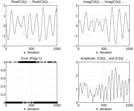
(2) The reversal phenomenon
In the decision-directed mode, the channel estimate (the prediction) and the data estimate (the
decision) are coupled (27-29). The coupling causes an interesting "reversal phenomenon," in
which the measured MSE is much larger than the theoretical one [22]. The term "reversal
phenomenon" reflects the fact that the estimates are close to the opposites of the actual channel
coefficients; they have phase difference close to π. As illustrated in Figure 2, the channel estimates
and channel coefficients are "reversed" between iterations 300 and 600. During this interval,
almost all the decisions are incorrect. Observations show that the reversal phenomenon starts
during deep fades — when the magnitudes of the channel coefficients are quite small. In deep
fades, the decision errors are likely to occur, and the Kalman estimator will produce inaccurate
The following arguments help to explain the reversal phenomenon. Substituting the received
signal z(k) (18) into (29) (ignoring the noise term v(k)), we have ˆ
X(k+1)=A ˆX(k)+K(k) { H(k) X(k)ˆ −H(k) ˆˆ X(k) }. (31)
Suppose the decision is wrong, i.e., ˆb(k)= −b(k). Then ˆH(k)= −H(k), and (31) becomes
ˆ
X(k+1)=A ˆX(k)−K(k) ˆˆ H(k){ X(k)+ ˆX(k) }. (32)
The sum of the actual channel coefficient state vector X(k) (5) (ignoring the noise term w(k)) and
the estimate (32) gives
X(k+1)+X(kˆ +1)={ A −K(k) ˆˆ H(k) }{ X(k)+X(k) }.ˆ (33)
If the Kalman filter is stable, i.e., the magnitudes of all the eigenvalues of the matrix
A −K(k) ˆˆ H(k) are less than one, the iteration of (33) goes to zero. This implies that X(k) will
have 180 degree phase shift relative to ˆX(k) as k increases. Thus, a sequence of incorrect
decisions may trigger the reversal phenomenon.
On the other hand, if the decision is correct, then ˆH(k)=H(k), and (31) becomes
ˆ
X(k+1)=A ˆX(k)+K(k) ˆˆ H(k){ X(k)− ˆX(k) }. (34)
Subtracting (34) from (5), we obtain
X(k+1)−X(kˆ +1)={ A −K(k) ˆˆ H(k) }{ X(k)−X(k) }.ˆ (35)
Equation (35) implies that a sequence of correct decisions will result in the tracking of ˆX(k) to
X(k) provided that the ignored noise terms are small.
These arguments and experimental results show that a few consecutive errors caused by a
deep fade are likely to trigger the reversal phenomenon. Once the reversal of the channel estimates
is established, the incorrect decisions continue to occur, even when the channel exits the deep fade.
This is because the decision is given by ˆb (k)=sgn(Re[z (k) ˆC*
(k)]), and when the estimate ˆ
C(k)≈ −C(k) , the decision is likely to be ˆb(k)= −b(k). The reversal typically continues until
another deep fade during which several "decision errors" (which are actually the correct decisions
now) may disrupt the convergence in (33) and bring the estimator back to (35). The long burst of
errors due to the reversal will raise the BER to the order of 10-1 even for high SNR values.
Therefore, the detector-estimator system must be designed to avoid the reversal phenomenon.
(3) Differential encoding
To avoid the catastrophic error events associated with the reversal phenomenon, we
originally proposed an ARQ scheme with the threshold detection since the amplitude of the channel
estimate can be used as the indicator of the fading channel condition [22]. If the amplitude is
smaller than the pre-determined threshold level, the channel is in a deep fade and the transmitter is
informed by the receiver to send a training bit next time. The method was not pursued further due
to the problems arising in the threshold level selection, the low throughputs, and the increased
delays. A more realistic and efficient solution is to encode the data bits differentially [30]. The
b(k) ⊕ a(k-1), where ⊕ is the addition mod-2 (exclusive OR). During the reversal, although the
phases of most decisions are shifted by π relative to the transmitted bits, most of the differences
between the consecutive transmitted bits are not changed. Therefore, the data bits encoded as the
differences between the consecutive transmitted bits should be preserved during the reversal
interval. The errors occur only at the beginning and the end of the reversal or are sparsely scattered
within the reversal interval.
Both coherent and noncoherent detection can be applied to demodulate the differentially
encoded data [30]. We denote coherent detection by Differentially Coherent Phase Shift Keying,
or DC-PSK, and noncoherent detection by Differential Phase Shift Keying, or DPSK.
Throughout the paper, we consider binary symbols only. In coherent detection, the estimate of the
phase reference is needed to demodulate the transmitted bits. The received bits then go through the
differential decoder to generate the data bits. In noncoherent reception, detection is performed
directly using the received signal. Since it requires no channel estimation, it is much simpler and is
widely used in communications for fading channels; however, its performance is usually poorer
than that of coherent reception.
In the context of multiuser detection, the use of the DPSK is limited to the detectors which
do not require channel estimation for the MAI reconstruction. For example, in our study, possible
choices are the decorrelator [31], the SIC-MF, and the PIC. The output of the decorrelator is
identical to that of a single user system with enhanced noise. Therefore, the decision process does
not involve interference reconstruction. The SIC-MF and the PIC reconstruct the MAI, but they
use the matched filter outputs and do not require channel estimates. Thus, noncoherent detection
can be applied. On the other hand, for the 2S and the DF detectors, or any other decision-based
MAI canceling type multiuser detector, channel estimation must be performed in order to
reconstruct and cancel the MAI. Since the channel estimates are available, it makes sense to use
coherent reception (DC-PSK) for these multiuser detectors.
(4) Disjoint estimation
A single user or a multiuser receiver for fading channels can be decomposed into a detector
and a channel estimator [32, 23]. In the context of multiuser receivers, it was shown in [23] that
the optimal joint channel estimator is also the Kalman filter provided the fading process obeys the
Gauss-Markov model. In joint estimation, a single Kalman channel estimator generates channel
estimates using the MF outputs and data bits of all users. Since joint estimation requires high
complexity, it is more desirable to use disjoint estimation. Instead of using a single Kalman filter
with a large dimension, we use N 'smaller' Kalman filters to estimate the channel coefficients for
each of the N users [11, 25]. Different from the joint Kalman filter, the disjoint Kalman filter uses
the output of the decorrelator as the observation process since it is independent of other users' data
decorrelator as the observation process because they both use the decorrelator in the front end (see
Figure 3). The outputs of succeeding stage of the DF and the 2F could be used as the observation
process for the Kalman filters in these two multiuser receivers; however we did not consider this
implementation in our work due to the dependency on the data bits of other users.
IV. BER Analysis
In this section, we briefly summarize our analysis tool--the unified analysis [33-34], and
apply it to obtain the BERs of several multiuser detectors. The BERs of the decorrelator, the 2S,
and the DF with MMSE channel estimators for BPSK modulation assuming perfect decisions of
other users were derived in [14]. These theoretical results are extended to the differentially
encoded PSK, and verified by simulations in which the Kalman filters are operated in the
decision-directed mode. We also analyze the BERs of the conventional detector and the PIC with DPSK,
and verify them using simulations.
A. The unified analysis
In [33], Stein presented a generalized error rate expression of a binary communication
system which can be applied to both coherent and noncoherent reception under all the possible
conditions of correlations in signals and in the additive noise process. Recent applications of the
unified analysis include performance evaluation for communication systems in the presence of the
carrier noise [10, 14, 18, 35]. We summarize the result for the Rayleigh fading channel [25].
More detailed derivation can be found in [26, 34].
Suppose the decision variable in the receiver is obtained by d=Re{X Y*}, where X and Y
are zero-mean correlated complex Gaussian random variables. The error probability is
PE =Pr(d <0)= 1
2[1−
Mxy +Myx
Mxy −Myx
(
)
2+4MxxMyy
] (36)
where Mxx, Myy, Mxy, and Myx are the moments of functions of X and Y which are defined as
Mxx =E{ X
2
}, Myy =E{Y
2
}, Mxy =E{XY
*
}, Myx = E{YX
*
} (37)
B. BERs of multiuser detectors with perfect channel estimation
In this section we use the unified analysis to calculate the BERs of several multiuser
detectors with perfect channel estimation and BPSK modulation for flat Rayleigh fading channels.
Let us first consider the conventional detector with perfect channel estimation. The output of the
matched filter for user 1 is
y1(k)= Eb
1C1(k)b1(k)+ R1, j EbjCj(k)bj(k) j=2
N
∑
+n1(k).
Let X=y1(k) and Y=C1(k). To calculate the BER using the unified analysis, we assume b1(k)=1
and condition on bi(k) (bi(k)=±1, i=2, ..., N), so that y1(k) satisfies the Gaussian assumption.
Since the conditional error probabilities Pr(d<0|b1(k)=1,B) (B=(b2(k), ..., bN(k))) are the same for
the moments Mxx = Eb
1+ [R1, j] 2
Eb
j
j=2 N
∑
+N0, Mxy = Eb1 =Myx, and Myy =1. Note that the value
of B does not affect the above moments. Substituting these expressions into (36), we obtain:
PEconv = 1
2[ 1−
1
1 +
j=2
N
∑ [R1, j]2
Eb j Eb1
(
)
+1γ1]. (38)
From (38), the performance of the conventional detector is limited by the cross-correlation values
and the strengths of other users.
The BER of the PIC can be calculated similarly. From (4), the signal of user 1 after
canceling the MAI is
˜y1(k)= Eb1C1(k)b1(k)+ Rˆ1, j EbjCj(k)bj(k) j=2
N
∑
+nˆ1(k).
Let X= ˜y1(k) and Y=C1(k). Then Mxx = [ ˆR1, j]
2 Eb
j
j=1 N
∑
+ρN0, where ρ =[ ˜R R ˜RT]1,1,Mxy =Rˆ1,1 Eb
1 =Myx, and Myy =1. From (36), the BER of the PIC is:
PEPIC =
1
2[ 1−
1
1 +
j=2
N
∑ Rˆ
1, j Rˆ1,1
(
)
2Eb j Eb1
(
)
+ ρ [ ˆR1,1]2
(
)
( )
1γ1]
. (39)
Similarly to the conventional detector, the performance of the PIC is affected by the powers of the
interferers.
The BER of the decorrelator for flat Rayleigh fading channel was derived in [9]:
PEdec = 1
2[1−
1
1+[R−1]1,1/γ1] (40)
The BERs of the ideal DF and the 2S were discussed in [10, 14]. Their BERs are
asymptotically equal to the BER of the single user system.
C. BERs of multiuser detectors for differentially encoded data
As discussed in section III, differential encoding is required to avoid the error bursts due to
the reversal phenomenon. For multiuser detectors with coherent reception (DC-PSK), the BERs
can be approximated using the error rates of the BPSK system [30]:
PEDC−PSK =2 (1−PEBPSK) PEBPSK. (41)
This expression is based on the assumption that the decisions are independent. Although in the
decision-directed mode this assumption is not valid, the approximation (41) is still accurate for
high SNR values [26].
Consider the decorrelator, the 2S and the DF with the disjoint Kalman filters. The Kalman
filter is the MMSE estimator if the fading channel obeys the Gauss-Markov model. Assuming
phenomenon), we can calculate the BERs of these detectors using the unified analysis. For user i,
define the estimation error as ei(k)=Ci(k)−Cˆi(k) , and the normalized estimation error variance as
Γi =E{|ei(k)|
2
} E{ |Ci(k)|2}=E{|ei(k)|2}. The steady-state estimation error variance E{|ei(k)|2}
(=Σ(k)1,1) is calculated by the Riccati equation (10). To compute the BER of the decorrelator [11],
let X=z1(k)= Eb
1C1(k)b1(k)+v1(k) (see (2)) and Y =Cˆ1(k). Then, PEdec, Mismatch =
1
2[1−
1− Γ1
1+[R−1]1,1 γ1]
(42)
For the 2S, we let X be the output signal of the second stage after the MAI cancellation and Y be
the channel estimate generated from the Kalman filter, i.e.,
X = Eb1C1(k)b1(k)+ i=2
N
∑
Ebi{Ci(k)−Cˆi(k)}bi(k)+n1(k) , Y= ˆC1(k).It is assumed that the current decisions of other users are correct. The lower bound on the BER of
the 2S for BPSK modulation is [14]
PE2 S, Mismatch≥ 1
2[1−
1− Γ1
1+ (Ebi Eb1)[R1,i]2 Γi + 1γ1 i=2
N
∑
](43)
The lower bound of the DF is the same as that of the 2S [14]. Note that in addition to the channel
estimation error of the desired user (user 1), the performance of the 2S and the DF is also
determined by the estimation errors of other users. Once the BERs of these detectors with BPSK
are calculated ((42) and (43)), the BERs of the coherent reception for the differential encoding
(DC-PSK) can be approximated by (41).
Note that the BERs of all three detectors saturate for high SNR values. The error floors are
determined by the limiting value of the estimation error variance, which increases as the Doppler
shift grows [14]. Although performance of all detectors degrades as the fading rate increases, the
degradation is less pronounced for the decorrelator than for the 2S and the DF detectors, since its
performance does not depend on the estimation errors of the interferers. In fact, the error floors of
the decorrelator and the single user system are the same [25], and are lower than the error floors of
the 2S and the DF [14].
For noncoherent reception with differential encoding (DPSK), the BERs of the
decorrelator, the PIC, and the conventional detector are obtained as follows. The decision variable
of user 1 for the decorrelator with DPSK is d= −Re{z1(k)z1
*
(k−1)}, and the error probability is
PEDPSK =Pr{d≥0 data= −1} where the event that data=-1 is equivalent to b1(k-1)=b1(k). Let
X= z1(k) and Y= z1(k−1) and apply (36). Then the BER of decorrelator with DPSK is [25]
PEdec, DPSK = 1
2[ 1−
Φ(1)
1 + [R
−1] 1,1
γ1
]
where Φ(1) is the autocorrelation function of C(k) evaluated at one sampling period (see equation
23). Note that the BER of noncoherent reception (DPSK) depends on the fading channel
parameters, quantified by Φ(1) .
To calculate the BER of the PIC with DPSK, we substitute the random variable X by the
signal of user 1 after MAI cancellation (4):
X = ˜y1(k)=Rˆ1,1 Eb1C1(k) b1(k)+
j=2 N
∑
Rˆ1, j Eb jCj(k) bj(k)+nˆ1(k).
The random variable Y is the delay version of the signal, i.e., Y= ˜y1(k−1). Since the conditional
error probabilities (conditioned on bi(k) and bi(k-1) (i=2, ..., N)) are identical, the BER of the PIC
with the DPSK is [15]
PEPIC, DPSK = 1
2[ 1−
Φ(1)
1 +
j=2 N
∑
Rˆ1, jˆ R1,1 2 Ebj
Eb 1 + ρ
[ ˆR1,1]2
1 γ1 ]. (45)
Similarly, let X and Y be the consecutive MF output of the desired user, i.e., X= y1(k) and
Y= y1(k−1), we obtain the BER of the conventional detector with DPSK [15]
PEconv, DPSK =[ 1−
Φ(1)
1 +
j=2 N
∑
R1, j2 EbjEb1 + 1 γ1 ]. (46)
From (44-46), the BERs of all these detectors with DPSK depend on the fading rate, which is
quantified by Φ(1) . If the fading channel is modeled by the AR2, Φ(1)= −a1 (1+a2). For actual
fading channel (modified Jakes model), Φ(1)=J0(2π fd T ). The performance of the conventional
detector and the PIC with DPSK also depends on the signal strengths of the interferers. The BER
of the decorrelator with DPSK is not affected by the powers of the interferers and therefore, it is
near-far resistant.
V. Numerical Examples
In this section, we compare the performance of multiuser detectors for several CDMA
channels. The analytical results are plotted using lines and the simulations are presented by
symbols (circles and plus signs), except for the SIC curves which are evaluated entirely by
simulations. The BERs of the 2S and the DF are almost the same and only the results for the 2S
are shown here.
Example 1: The effect of the cross-correlation (Figure 4)
First consider the simplest CDMA channel - the 2-user channel. Figures 4(a) and 4(b) show
the results with the cross-correlation values of 0.5 and 0.9, respectively. Both users have equal
average path strengths or SNRs (γ1=γ2). The performance of all multiuser detectors degrades as
The PIC and the SIC-MF perform almost the same as the decorrelator in this case. Among
three successive interference scheme, the SIC-HD has the best performance and the SIC-MF has
the worst. This is expected since we assume the amplitude and phase of the interferer are known
in the SIC-HD. Therefore, the MAI estimate generated in the SIC-HD gives the best
approximation of the actual MAI and the cancellation is most complete. Note that the SIC-HD, as
well as the 2S and the DF, are very close to the single user bound. Although this two-user
example describes dependence of multiuser detectors on the cross-correlation, it does not
completely illustrate several other relationships, especially for the SIC and PIC detectors.
Therefore, we consider the cases of more users in the following examples.
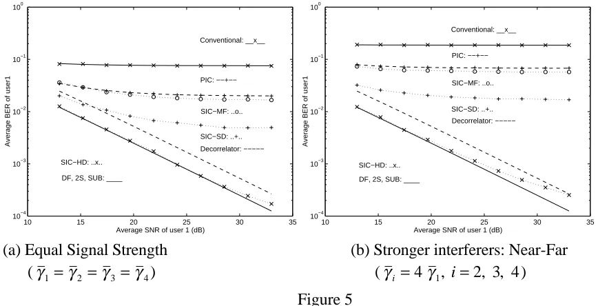
Example 2: The effect of the interferers' powers (Figure 5)
Figure 5 shows the simulation results for the four-user case. Figure 5(a) shows the case of
equal strengths and Figure 5(b) shows the near-far scenario where interferes have stronger power
(6 dB more) than the desired user. The set of signature waveforms is derived from the Gold
sequences of length seven [10]. The performance of the decorrelator, the DF, and the 2S are not
affected by the strength of other users whereas the performance of the PIC and the SIC is.
The SIC and the PIC degrade significantly for the four user channel in comparison with the
2-user channel. The two-user channel is a special case for the SIC and the PIC schemes since
there is only one MAI component in the received signal, and it can be mostly removed. For a
greater number of users, the MAI is canceled successively in the SIC. Therefore, a portion of the
MAI due to stronger interferers remains uncanceled and deteriorates the performance of weaker
users. For the PIC, since the MAI estimate is very noisy, the parallel MAI cancellation removes
the major part of the MAI, but at the same time, adds in a significant amount of interference. The
additional interference is due to the rough MAI estimates obtained from the outputs of the matched
filter bank, which contain not only the desired signal, but also signals of the other users.
Although our results for the SIC-SD show that its performance degrades significantly when
the number of users increases, it has been demonstrated that the SIC can provide acceptable
performance in [5]. The difference between these results is due to the fact that a much larger
processing gain is utilized in [5]. Since the scenario considered in [5] is close to the IS-95
standard, the SIC schemes should still be considered as strong multiuser detection candidates for
current CDMA systems because of their reasonably good performance and low complexity.
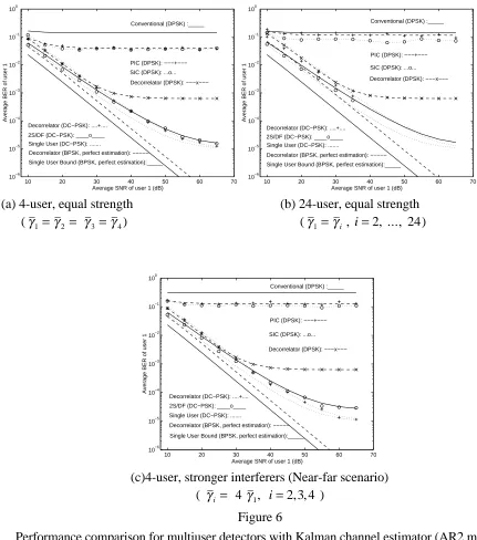
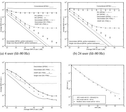
Example 3: The effect of the estimation errors and the near-far problem (Figure 6)
In this example, we model the channel by the AR2 process. The fading channel model
parameters in (20) are chosen as follows: the spectral peak frequency ( fd′) is 80 Hz; the Doppler
shift ( fd) is approximately 113 Hz, which corresponds to the carrier frequency of 900 MHz and
peaks in the power spectrum. By (20), the coefficients of the second order AR process are a1
=-1.99348, a2=0.996.
The cross-correlation matrices R for 4-user and 24-user cases are derived from Gold
sequence of length 7 and 31 respectively. In particular, for the case of 24 users, we choose 24
Gold sequences of length 31, and cyclically shift each sequence by +1 chip or -1 chip. The
purpose is to account for the effect of imperfect symbol-level synchronization, and to mimic the
asynchronous CDMA channel. With this arrangement, the off diagonal elements of R will have
one of the three values: {-1/31, -9/31, 7/31}.
Figure 6(a) and Figure 6(b) show the results for 4 and 24 users with equal strength. Let us
first focus on the coherent multiuser detectors (DC-PSK): the decorrelator, the 2S, and the DF. It
is noted that for a single user system, the limiting value of the normalized error variance, Γ, is the
same as that of the decorrelator [25]. Therefore, the decorrelator has the same error floor as the
single user system, i.e. the decorrelator asymptotically approaches the single user bound in this
case. On the other hand, the limiting BERs of the 2S and the DF are higher than that of the single
user system because of the contribution of other users' estimation errors (
i =2 N
∑
(Ebi Eb1)[R1,i]2 Γ in(43)) [14]. This result is quite different from the case of perfect channel estimation in which the
performance of the 2S and the DF asymptotically approaches that of a single user system [10].
Further comparison with the case of perfect channel estimation shows that the performance gain of
the 2S and the DF over the decorrelator is not as significant when channel is mismatched.
For multiuser detectors with noncoherent reception (DPSK), such as the conventional
detector, the PIC, the SIC, and the decorrelator, the tradeoff between the complexity and
performance is obvious. The conventional detector has BER of the order of 10-1, which is
unacceptable for most applications. For more than two users and in the highly interference-limited
environment, the PIC and the SIC schemes also reach high error floors due to the MAI. The
superior performance of the decorrelator indicates that the enhancement of the background noise is
a small price to pay for the MAI elimination. The error floor of the decorrelator is due to the nature
of the fading channel.
We also investigate the near-far scenario, illustrated by a 4-user case, shown in Figure 6(c).
When the interferers are stronger than the desired user (user 1) by 6 dB, we find that the
performance of the 2S and the DF degrades compared with the case of equal strength (see Figures
6(a) and 6(c)). This is again a different result when compared with the perfect channel estimation
case [10]. For the perfect channel estimation case, in the near-far scenario, decisions of interferers
in the 2S and the DF are more reliable and the MAI cancellation is more complete than in the case
of equal strength. Therefore, the 2S and the DF are closer to the single user bound when
residual interference is the dominant factor of the performance of the 2S and the DF for high SNR.
In the near-far scenario, the residual interference is greater than that of the equal strength case, and
therefore the 2S and the DF perform worse in the near-far scenario. This is due to the following
reason. Although in the near-far scenario the estimation errors Γi of other users are reduced
compared with those of the equal strength case, the total power of the resultant residual interference
i =2 N
∑
(Ebi Eb1)[R1,i] 2 Γ
is greater than that of the equal strength case due to higher power ratios
(Eb
i Eb1) . The performance degradation of the 2S and the DF in the near-far scenario is more
obvious in high SNR since the estimation error converges to the limiting value Γi and cannot be
further reduced. The performance of the PIC and the SIC shows that they are less suitable for high
bandwidth efficiency systems than more complex detectors.
Example 4: The effect of the Doppler shift (Figure 7)
In Figures 7(a) and 7(b), the performance of the multiuser detectors with different Doppler
frequencies for a two-user channel (cross-correlation r=0.9) is compared. In Figures 7(a) and
7(b), the spectral peak frequencies for the AR2 process are 80 Hz and 40 Hz, respectively. They
are approximately equal to the maximum Doppler frequency 113 Hz and 56 Hz. Comparing these
two figures, we find that for the lower Doppler shift, the error floors are lower and the cross-over
point of the decorrelator and the 2S occurs at higher SNR value (45 dB instead of 40 dB). This
means that for the lower Doppler frequency, the channel estimation errors are reduced, and the 2S
(or the DF) performs better than the decorrelator for a larger operation region.
The dependency of the error floor values on the Doppler shift is explained by considering the
limiting value of the normalized estimation error variance, Γ1 in (42-43), as the additive Gaussian
noise becomes negligible. For the AR2 process, this value is given by the variance of the
excitation noise in (19) [14]. From the expression derived in [14], it is evident that the limiting
value of Γ1 monotonically increases with the fading rate. Thus, the higher the fading rate, the
higher the error floors are. In addition, as the Doppler shift increases, the terms due to the channel
estimation errors of the interferers increase (see (43)), and limit the performance of the 2S and the
DF detectors.
Example 5: The Jakes model (Figure 8)
In this example, we simulate several cases using a more realistic channel model--the
modified Jakes model. We use 24 distinct oscillators (Nd=24), or 96 oscillators in total. By using
the Walsh-Hadamard codewords, we can generate at most 24 uncorrelated fading waveforms. The
parameters in the Kalman filter are chosen based on the approximate AR2 hypermodel of the
modified Jakes model, as discussed in Section III. When the Kalman filter estimates the channel
coefficients generated by the modified Jakes model in the decision-direction mode, the reversal
Figures 8(a) and (b) show the results for 4 and 24 users. The Doppler frequency is 80 Hz
and the sampling rate is 10 Kbps. The Doppler frequency corresponds to the carrier frequency 900
MHz and vehicle speed of 60 mph. The signature cross-correlation matrices used here are the
same as in examples 1-4. The results are similar to those in Examples 3 and 4. Although the error
floors of the 2S and the decorrelator are not obvious when the modified Jakes model is used, they
do exist. In Figure 8(c), we simulate a two-user scenario (cross-correlation r=0.9) and
demonstrate that these error floors exist by increasing the Doppler frequency to 500 Hz. It is
interesting to see that in this extreme case, the 2S or the DF performs worse than the decorrelator
for all the considered operation SNR values due to the effect of channel estimation errors.
In section III we showed that the fading process created using the modified Jakes model with
the Doppler frequency fd can be approximated well by the second order AR process with the
spectral peak frequency fd′ = fd 2 . In Figure 8(d), we verify this fact by plotting the BERs of
the two-stage detector with different channel models for a two-user channel (cross-correlation
r=0.9). We observe that the performance is similar for different models, and the factor of 2
adjustment provides a better approximation.
VI. Conclusions and Future Work
In this paper, we evaluated the performance of several multiuser detectors under the ideal
perfect channel estimation assumption and under channel mismatch. In the case of perfect channel
estimation, the more complex detectors (the 2S and the DF) can effectively eliminate the MAI and
achieve the performance of the single user system, even for high bandwidth efficient channels.
The simpler schemes, such as the SIC and PIC, are not as suitable for the use in the high
bandwidth efficient channels. In the presence of the channel mismatch, the performance of the
coherent multiuser detectors--the decorrelator, the 2S, and the DF, is comparable. The
performance degradation of the 2S and the DF is due to the channel estimation errors of all users
whereas the decorrelator is only affected by the desired user. The decorrelator outperforms the 2S
and the DF in the high SNR region and preserves the near-far resistance. For noncoherent
multiuser detectors, the decorrelator has a large performance gain over the SIC and the PIC. These
results indicates that the decorrelator is the most robust multiuser detector for the realistic fading
channels.
We also verify that the Kalman filter can be used to estimate a realistic fading channel even if
the channel does not exactly obey the Gauss-Markov model. A second order AR process can be
used as the hypermodel in the Kalman filter. To avoid the burst errors due to the reversal
phenomenon when using the decision-directed Kalman filter, differentially encoded data is
Future work will concentrate on the performance evaluation of multiuser detectors for the
frequency-selective fading CDMA channels, and other channel estimation methods.
References
[1] A. Duel-Hallen, J. Holtzman, Z. Zvonar, "Multiuser Detection for CDMA System," IEEE Personal Communication Magazine, April 1995, pp. 46-58.
[2] R. Lupas, S. Verdu, "Linear Multiuser Detectors for Synchronous Code-Division Multiple-Access Channel," IEEE Transactions on Information Theory, Vol. IT-35, No. 1, Jan. 1989, pp. 123-136.
[3] M.K. Varanasi, B. Aazhang, "Near-optimum Detection in Synchronous Code-Division Multiple Access Channel," IEEE Transactions on Communications, Vol. COM-39, No. 5, May 1991, pp. 725-736. [4] A. Duel-Hallen, "Decorrelating Decision-Feedback Multiuser Detector for Synchronous Code-Division
Multiple Access Channel," IEEE Transactions on Communications, Vol. COM-41, No. 2, Feb. 1993, pp. 285-290.
[5] P. Patel, J. Holtzman, "Analysis of a Simple Successive Interference Cancellation Scheme in DS/CDMA System," IEEE J-SAC - Special issue on CDMA, Vol. 12, No. 5, June 1994, pp. 796-807.
[6] P. Patel, J. Holtzman, "Performance Comparison of a DS/CDMA system using a Successive Interference cancellation (IC) scheme and a Parallel IC Scheme under Fading," ICC 94, pp. 510-515, New Orleans, LA, 1994.
[7] N.B. Mandayam, S. Verdu, "Analysis of an Approximate Decorrelating Detector," Proc. of Thirty-Third Annual Allerton Conference on Communication, Control and Computing, Monticello, Oct. 1995, pp. 1043-1052.
[8] Z. Zvonar, D. Brady, "Coherent and Differentially Coherent Multiuser Detectors for Asynchronous CDMA frequency-selective Channels," Proc. IEEE MILCOM '92, Dan Diego, CA, 1992, pp. 17.6.1-17.6.5. [9] Z. Zvonar, D. Brady, "Multiuser Detection in Single-Path Fading Channels," IEEE Transactions on
Communication, Vol. COM-42, No. 4, April 1994, pp. 1729-1739.
[10] H.Y. Wu, A. Duel-Hallen, "Performance of Multiuser Decision-Feedback Detectors for Flat Fading
Synchronous CDMA Channels," Proc. of the 28th Annual Conference on Information Sciences and Systems, Princeton University, Princeton, NJ, March 1994, pp. 133-138.
[11] Z. Zvonar, D. Brady, "A Comparison of Differentially Coherent and Coherent Multiuser Detection With Imperfect Phase Estimates in a Rayleigh Fading Channel," Proc. of the 1993 International Symposium on Information Theory, p. 48.
[12] Z. Zvonar, M. Stojanovic, "Performance of Multiuser Diversity Reception in Nonselective Rayleigh Fading CDMA Channels," Proc. of the Third Communication Theory Mini-Conference (CTMC '94), San Francisco, CA, Nov. 1994, pp. 171-175.
[13] H.Y. Wu, A. Duel-Hallen, "Multiuser Detection with Differentially Encoded Data for Mismatched Flat Rayleigh Fading CDMA Channels," Proc. of the 30th Annual Conference on Information Sciences and Systems, Princeton University, Princeton, NJ, March 1996, pp.332-337..
[14] H.Y. Wu, A. Duel-Hallen, "Performance Comparison of Multiuser Detectors with Channel Estimation for Flat Rayleigh Fading CDMA Channels," Wireless Personal Communications, Special Issue on "Interference in Mobile Wireless Systems," Kluwer, in press.
[15] H.Y. Wu, A. Duel-Hallen, "On the Performance of Coherent and Noncoherent Multiuser Detectors for Mobile Radio CDMA Channels," Proceedings of 6th IEEE International Conference on Universal Personal
Communications (ICUPC 96), Oct. 1996, Cambridge, MA, pp. 76-80.
[16] P.Y. Kam, C.H. Teh, "An Adaptive Receiver with Memory for Slowly Fading Channels," IEEE Transactions on Communications, Vol. COM-32, pp. 654-659, June 1984.
[17] R. Haeb, H. Meyr, "A Digital Synchronizer for Linearly Modulated Signals Transmitted over a Frequency-nonselective Fading Channel," IEEE ICC, June 1988, pp. 364-370.
[18] R. Haeb, H. Meyr, "A Systematic Approach to Carrier Recovery and Detection of Digitally Phase Modulated Signals on Fading Channels," IEEE Transactions on Communications, Vol. 37, No. 7, July 1989, pp. 748-754.
[19] W.C. Jakes, Jr., Microwave Mobile Communication, John Wiley & Sons, New York, 1974, p. 75.
[20] P. Dent, G.E. Bottomley, T. Croft, "Jakes Fading Model Revisited," IEEE Electronics Letters, Vol. 29, No. 13, June 1993, pp. 1162-1163.