Implementation of High Performance Area
Efficient Architecture for Z-TCAM
Geethu Sabu 1, Jemti Jose 2
PG Scholar, Department of Electronics and Communication, MG University, St.Josephs College of Engineering and
Technology, Kerala, India1
Assistant Professor, Department of Electronics and Communication, St.Josephs College of Engineering and
Technology, Kerala, India2
ABSTRACT: The ternary content addressable memory (TCAM) is a type of memory that allows the memory to be searched by content rather than by address. It performs high-speed search and network routing operations in a deterministic time. The conventional TCAM circuitry has certain shortcomings compared to the RAM technology, such as low access time, low storage capacity, high circuit complexity and high cost. Therefore, we can use the benefits of SRAM by configuring it to behave like TCAM. A novel memory architecture based on the hybrid partitioning concept, known as the Z-TCAM, emulates the TCAM functionality with SRAM. The searching operation of data in memory and area are the main problems that are faced by the user. It increases power consumption, cost and access time. So, the design can be enhanced by an area efficient implementation of the architecture and also by introducing a parity bit to boost the searching speed of SRAM based TCAM with less delay. Thus area efficient SRAM based TCAM with parity bit offers better search performance, high area efficiency, higher operating speed, lower latency and scalability. The hybrid partitioned SRAM based TCAM architecture is verified by Verilog in ISim simulator and implemented on Xilinx Spartan6.
KEYWORDS:Hybrid Partitioning (HP), Parameter extractor, Priority Encoder (PE), Static Random Access Memory (SRAM)-based TCAM, Ternary Content Addressable Memory (TCAM )
I. INTRODUCTION
Memory is considered as the workspace for the processor. It is a temporary storage area where the programs and data being operated on by the processor must reside. Memory is the internal storage media of computer and is mainly categorized into two types, Primary memory and Secondary memory. The primary storage is referred to as random access memory (RAM), which is the central storage unit of a computer system. It is the place in a computer where the operating system, application programs and the data currently used are kept temporarily so that they can be accessed by the computer's processor. Secondary memory is external and permanent memory that is useful to store the external storage media such as floppy disk, magnetic disks, magnetic tapes and cache devices and is also referred to as ROM or Read Only Memory.
The ternary content addressable memory (TCAM) is an outgrowth of random access memory (RAM) but unlike RAM, TCAM provides access to the stored data by contents rather than by an address and outputs the match address. TCAM is a specialized CAM designed for rapid table lookups. A TCAM cell has two static random access memory (SRAM) cells and a comparison circuitry and extends to three state: 0, 1, and x where x is a don't care state. The x state is always regarded as matched irrespective of the input bit. Since TCAM provides high speed parallel search operation, it has a wide range of applications such in network routers, translation look-aside buffers in microprocessors, data compression, real-time pattern matching in the virus-detection and intrusion-detection systems, gene pattern searching in bioinformatics, and image processing . The prime application of TCAM is in the network systems where to compare the destination address of incoming packet against the stored addresses and to forward the packet to the appropriate output port.
Even though CAM technology presents a major advantage of a single clock cycle comparison over standard RAM, but it also has its shortcomings. TCAM is not exposed to the intense commercial competition found in the RAM market and is also less dense than SRAM. The comparator's circuitry in the TCAM cell adds complexity to the TCAM architecture. The extra logic and capacitive loading due to immense parallelism prolongs the access time of TCAM, which is 3.3 times more compared to the SRAM access time. Inborn architectural barriers also limit the total chip capacity of TCAM. Complex integration of memory and logic also makes TCAM testing process time consuming. High-power consumption increases junction temperature, which further increases the leakage currents, reduces chip performance, and degrades reliability of CAM devices Furthermore, the cost of TCAM is around 30 times more per bit of storage than SRAM. Pattern capacity in CAM devices is very limited. CAM technology does not evolve with the same pace as RAM technology. RAM technology is driven by many applications, specially computers and consumer electronic products, and therefore the cost per bit is continuously decreasing, as opposed to CAM technology .RAMs develop in a wider variety of sizes and flavours. It is more generic and widely available and enables to evade the heavy licensing and royalty costs charged by some CAM vendors.
II. MATERIALS AND METHODS
TCAM consists of cells, which are arranged in the form of a two dimensional array. Cells in the same row (TCAM word) share a matchline (ML) and cells in the same column share searchlines (SLs). A conventional TCAM array is shown in Figure 1, which shows a 4 x 3 TCAM array consisting of 4 rows (TCAM words) and 3 columns. Each TCAM word has its corresponding ML and cells in the same column are connected to its corresponding SLs. For a search operation, all the MLs must be pre-charged to and SLs must be discharged to ground in a conventional TCAM before the search key is to be applied. Then, the search key is applied to all SLs in parallel. If a match occurs, ML stays at its pre-charged value; otherwise it discharges to Gnd through the comparison circuitry of the TCAM cell. An ML stays at only, if all the cells sharing the same ML have a match condition. Otherwise, a mismatch in any cell sharing the same ML will discharge that ML to Gnd. MLs are fed to a priority encoder (PE).
III.RELATED WORK
A CAM is a memory that implements the lookup-table function in a single clock cycle using dedicated comparison circuitry. The main CAM-design challenge is to reduce power consumption associated with the large amount of parallel active circuitry, without sacrificing speed or memory density. At the architectural level, three methods for reducing power consumption are discussed by Kostas Pagiamtzis et al[1]. However, the speed of a CAM comes at the cost of increased silicon area and power consumption, two design parameters that designers strive to reduce. As CAM applications grow, demanding larger CAM sizes, the power problem is further exacerbated. Reducing power consumption, without sacrificing speed or area, is the main thread of recent research in large-capacity CAMs. First, a straightforward architectural technique that saves power is bank-selection, where only a subset of the CAM is active on any given cycle. The basic concept is that bank selection divides the CAM into subsets called banks. The major drawback of bank selection is the problem of bank overflow. The second architectural technique for saving power, which applies only to binary CAM, is pre-computation. Pre-computation stores some extra information along with each word that is used in the search operation to save power. The third architectural concept for saving power is to change the encoding of stored data in the CAM cell.
A ternary CAM (TCAM) is used to perform a fully parallel search across the entire data set. Unfortunately, this parallelism means that large portions of the chip are switching during each cycle, causing large amounts of power to be consumed. The structure of a modern TCAM is examined to present a simple, yet accurate, power and delay model by Banit Agrawal et al[2]. In TCAM structure, in particular, we concentrate primarily on the aspects relating to search as this dominates the overall system power on an active device. A XNOR-based TCAM structure is designed and it has three major components: the precharge unit, the actual array of TCAM cells, and the priority encoder. An accurate TCAM power model can be built through the calculation of match and select line capacitances by considering both the wire length and loading of these lines. A novel memory architecture, named Z-TCAM, which emulates the TCAM functionality with SRAM, is proposed by Zahid Ullah et al[3]. Key benefits of Z-TCAM over conventional TCAM are given below:
The proposed Z-TCAM is simpler, and easily scalable (owing to easy scalability of SRAM) for large size TCAM.
The proposed TCAM follows the development trends of SRAM, which are much faster than conventional TCAM.
Classical TCAM uses match-line and XOR gates for comparison operations. The match-lines in classical TCAM are very capacitive and consume much time for charging and discharging. There is the physical limit in increasing speed for classical TCAM because of such intrinsic structure. However, the proposed approach mainly uses SRAM read operations for comparisons. The speed of the proposed TCAM is only limited by the read speed of SRAMs. This speed can be much higher than the speed of classical TCAM.
The limitations of CAM over RAM is discussed and an implementation of a SRAM-based TCAM, SR-TCAM, is presented by Zahid Ullah et al[4]. TCAM is not subjected to the intense commercial competition found in the RAM market. TCAM is less dense than SRAM. The comparator's circuitry in TCAM cell adds complexity to the TCAM architecture. The access time of TCAM is 3.3 times longer than the SRAM access time. Inborn architectural barriers also limit the total chip capacity of TCAM. Complex integration of memory and logic also makes TCAM testing very time consuming. Furthermore, the cost of TCAM is about 30 times more per bit of storage than SRAM.
IV. CONVENTIONAL Z-TCAM ARCHITECTURE
A. HYBRID PARTITIONING OF TCAM TABLE
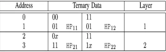
TABLE I Conventional TCAM table
HP partitions the conventional TCAM table vertically (column-wise) and horizontally (row-wise) into TCAM subtables, which are later processed to be stored in their corresponding memory units. We divide conventional TCAM table along columns (vertical partitions) and rows (horizontal partitions) which results in TCAM subtables. Each TCAM subtable is termed as hybrid partition and the collective partitioning technique (vertical and horizontal) is called HP. The function of vertical partitioning (VP) part of HP is to divide the TCAM word of C bits into N subwords, where each subword is of w bits. Thus, VP divides the entire TCAM table into N vertical partitions. Horizontal partitioning (HrP) part of HP divides each vertical partition into L horizontal partitions by making use of the original address range of the conventional TCAM table. Thus, HP results in a total of LxN hybrid partitions. Dimension of each hybrid partition is Kxw, where K is a subset of original addresses and w is the number of bits in a subword. Here TCAM table is partitioned into two layers as layer 1 and layer 2 by vertical partitioning. Horizontal partitioning HP11, HP12, HP21 and HP22 are formed by dividing each of these layers. Also, vertical partitioning effectively reduces the size of the memory.
B. Z-TCAM architecture
1) Overall architecture
The overall architecture of classical Z-TCAM is depicted in fig. 2 where each layer represents the architecture shown in figure 3. It has L layers and a CAM priority encoder (CPE). Each layer outputs a potential match address (PMA). The PMAs are given as inputs to CPE, which selects the match address (MA) among PMAs.
Fig.2: overall architecture of Z-TCAM
2) Layer architecture
Fig.3: Layer architecture
Validation Memory: Size of each VM is 2w x 1 bits where w represents the number of bits in each subword and 2w shows the number of rows. A subword of w bits denotes that it has total combinations of 2w where each combination represents a subword. For example, if w is 4 bits, then it means that there are a total of 24 = 16 combinations. This explanation is also related to both OATAM and OAT. Each subword acts as an address to VM. If the memory location invoked by a subword is high, it implies that the input subword is present, else absent. Thus, VM validates the input subword, if it is present.
1-bit AND Operation: It ANDs the output of all the VMs. The output of 1-bit AND operation decides the continuation of a search operation. If the output of 1-bit AND operation is high, then it permits the continuation of a search operation, otherwise mismatch occurs in the corresponding layer.
Original Address Table Address Memory: Size of each OATAM is 2w xw bits where 2w is the number of rows and each row has w bits. In OATAM, an address is stored in the memory location indexed by a subword and that address is then used to invoke a particular row from its corresponding OAT. If a subword in the VM is mapped, then a corresponding address is also stored in OATAM in a memory location accessed by the subword. The output of OATAM is called as OATA. Hyphen ‘-‘ indicates that the corresponding memory location has no data because the corresponding subword for the memory location is not present in VM.
Original Address Table: Dimensions of OAT are 2wxK where w is the number of bits in a subword, 2w represents number of rows and K represents the number of bits in each row where each bit represents an original address. Here K is a subset of original addresses from the conventional TCAM table. It is OAT, which considers the storage of original addresses
.
K-bit AND Operation: It ANDs bit-by-bit the K-bit row outputs from all OATs and forwards the result to LPE.
Layer Priority Encoder: Since multiple matches can occur in TCAM, the LPE selects PMA among the outputs of K-bit AND operation.
C. Z-TCAM Operation
1) Data mapping operation
TCAM word 010x, it is then expanded into 0100 and 0101. Each subword, acting as an address, is applied to its corresponding VM and logic “1” is written at that memory location. The same subword is also applied to its respective OATAM and w bit data is written in that memory location. During search, these w bit data act as an address to the OAT. The K bit data is also written in the memory location in OAT determined by its corresponding OATA. Thus, in this way, all hybrid partitions are mapped.
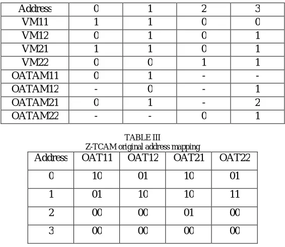
A subword may exist at multiple locations in a hybrid partition. So, it is mapped in its corresponding VM and its original address (es) is/are mapped to its/their corresponding bit(s) in its respective OAT. Since a single bit in the OAT block indicate an original address, only those memory locations in VMs and address positions/ original addresses in OATs are high, which are mapped while the remaining memory locations and address positions are set to low in VMs and OATs, respectively. Example of data mapping is shown in Table II and Table III and use table in figure 1 to be mapped to SRAM based TCAM architecture. Here, we take N = 2, L = 2, K = 2, and w = 2. After necessary processing, HP11, HP12, HP21, and HP22 are mapped to their corresponding memory units.
TABLE II
Z-TCAM example: Data Mapping
Address 0 1 2 3
VM11 1 1 0 0
VM12 0 1 0 1
VM21 1 1 0 1
VM22 0 0 1 1
OATAM11 0 1 - -
OATAM12 - 0 - 1
OATAM21 0 1 - 2
OATAM22 - - 0 1
TABLE III
Z-TCAM original address mapping
Address OAT11 OAT12 OAT21 OAT22
0 10 01 10 01
1 01 10 10 11
2 00 00 01 00
3 00 00 00 00
2) Search operation:
Search operation in Z-TCAM architecture is acheived by applying the search key as input to the Z-TCAM architecture, which is then divided into N subwords of w bits. The input subwords are fed to all layers of Z-TCAM architecture in parallel. The search operation is performed in each layer and the resultant PMAs are available from all layers. For searching in a layer of Z-TCAM architecture, initially N subwords are concurrently applied to a layer. These subwords then read out the corresponding memory locations from their respective VMs. If all the VMs validate their corresponding subwords, then the search will continue, else mismatch occurs in the layer. Upon validation of all subwords, the subwords read out the respective memory locations from their corresponding OATAMs simultaneously and output their corresponding OATAs. All OATAs then output the K-bit rows from their corresponding OATs simultaneously, on which bitwise AND operation is performed. LPE selects PMA from the result of the K-bit AND operation. CPE selects the MA among PMAs; otherwise a mismatch of the input word occurs.
TABLE IV
Example of a search operation in Z-TCAM
Steps Activity
1 Search key = 0011
2 Subword1 = 00
Subword2 = 11
3 PMA1 = 00
PMA2 = 10
4 CAM priority encoder selects 0 as MA
V. MODIFIED Z-TCAM ARCHITECTURE
In the modified architecture, a parameter extractor is used in the proposed system to boost the searching speed and also to reduce delay. Also, memory mapping is done to make the architecture of Z-TCAM area efficient. This helps reduce the area of the architecture without affecting the processing time and the delay.
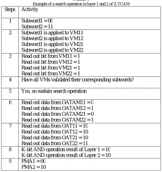
TABLE V
Example of a search operation in layer 1 and 2 of Z-TCAM
Steps Activity
1 Subword1 = 00
Subword2 = 11
2 Subword1 is applied to VM11 Subword2 is applied to VM12 Subword1 is applied to VM21 Subword2 is applied to VM22 3 Read out bit from VM11 = 1
Read out bit from VM12 = 1 Read out bit from VM21 = 1 Read out bit from VM22 = 1
4 Have all VMs validated their corresponding subwords?
5 Yes, so sustain search operation
6 Read out data from OATAM11 = 0 Read out data from OATAM12 = 1 Read out data from OATAM21 = 0 Read out data from OATAM22 = 1 7 Read out data from OAT11 = 10
Read out data from OAT12 = 10 Read out data from OAT21 = 10 Read out data from OAT22 = 11
8 K-bit AND operation result of Layer 1 = 10 K-bit AND operation result of Layer 2 = 10
9 PMA1 = 00
A. Parity Bit based Approach for Z-TCAM architecture
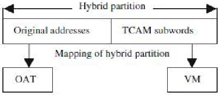
Z-TCAM architecture has higher power dissipation, as the number of comparison operations is more before validating particular search key is present in existing layers or not. So in order to reduce the number of comparison operations, a pre-computation based method known as Parity bit based approach, is introduced. Parity bit based approach reduces the power consumption by reducing the number of comparison operations. The comparison operation is reduced by using parameter extractor which extracts the parameter from input data, which is then compared with parameters stored in the parameter memory. If matches occur in the first part then data related to those matched parameters will be compared in the second part; otherwise no match condition is returned. The design goal of the parameter extractor is to filter out as many unmatched data as possible to effectively minimize the required number of comparison operations in the second part. Fig.4 shows the mapping of the hybrid partition into its corresponding memory blocks. In the case of modified Z-TCAM architecture, the corresponding memory blocks are the OAT and the VM. The original address are mapped to the OAT whereas the hybrid partitioned subwords are mapped to the VM. But in the case of the conventional Z-TCAM architecture, the memory blocks referred to here are the OATAM and the VM.
Fig. 4: Mapping of a hybrid partition to its corresponding memory blocks
Parity bit based approach for Z-TCAM architecture has the same interface as the conventional Z-TCAM with one extra bit. Parity bit is either odd or even. The extractor is used to find the parity bit value. During the search operation, the matched parity bit value of the search word is found first. Only the word whose parity bit value matched will be compared with the search word and this will reduce the comparison with the mismatched word. Therefore driving capacity of more mismatch word is stronger than that of the 1-mismatch word, the design greatly improves the search speed. This parity bit does not improve the power performance. This additional parity bit reduces the sensing delay and boosts the driving strength of the 1-mismatch case by half. Additional equipment is required for parity generation. In this architecture parameter extractor and parameter memory are used to generate and store the additional parity bit of stored and input data. The parameter extractor is used extract the input subwords and find out the parity bit (either 1 or 0). The parameter memory is used to store the stored words parity bit and result from parameter extractor is compared with it to determine the selective data for search. Thus the number of comparison is reduced to sensing delay.
In Parity bit based approach, if any word has don't care condition, then for both parity condition, we have to compare that word. If there is less number of words having don't care, then there will reduction in comparison operation. Here, we use XOR operation in order to obtain the parity bit. The outcome result is bit '1' for odd number of one's in data word and '0' for even number of ones. The parity bit of the words stored in the memory is computed and it is added as the MSB bit of the word, making the size of each stored word C+1. During search operation, the parity bit of the search word is immediately calculated and is compared with the parity bits or the MSB of the stored words. Only those stored words whose parity bit are found matched, are provided for the search operation. Thus the computation process is simplified. In this scheme only parity of 1's in the data word is checked. Therefore, single bit area is enough to store additional bit and that eases the computation process.
B. Area efficient architecture of Z-TCAM
mapping. The main advantages of this modified structure is that less resources thus less memory usage and resource utilization. Speed of operation is also increased.
In the modified Z-TCAM architecture, as shown in fig.5, the OATAM block is eliminated and direct mapping from VMs to OATs is done. This helps in reducing resource utilization and by reducing memory usage, the performance and speed is improved. The OATAM tables are very difficult to design and map, and as the number of bits in the input search word increases the OATAM table size also increase enormously. So by eliminating the OATAM table, we map the VMs directly with the OATs and thus the TCAM functionality is achieved. The data mapping and search operations are altered accordingly.
Fig.5: Layer architecture of area efficient Z-TCAM
1) Data mapping operation
The layer architecture is modified and thus the data mapping operation is changed such that each subword acts as an address and accesses a particular memory location in the respective memory blocks (VM and OAT). Each subword is
applied to its corresponding VM and a logic1 is written in that memory location. The same subword is also applied to
its corresponding OAT and K bits are written in that memory location. Thus, each subword in all hybrid partitions is mapped to its corresponding memory location in VM and the original address(es) of the same subword is/are mapped to
its/their respective bit(s) in the corresponding OAT, respectively. Also, a subword in a hybrid partition may occur at
multiple locations. So, it is programmed in the VM and its original addresses are mapped to their respective bits in OAT. A single bit in OAT represents an original address. Only those memory locations in VMs and original addresses in OATs which are mapped are set to high, while all the remaining memory locations and address locations are set to low in VMs and OATs, respectively.
2) Search operation
The modified Z-TCAM performs the search operation in all Llayers in parallel. The search key is applied to Z-TCAM,
which is then divided into Nsubwords of w bits each. The subwords are then searched in their corresponding pairs in
subwords act as addresses and outputs their corresponding memory locations from their respective VMs. Next, each accessed memory location provides a single bit, which can be 1 or 0. Presence of 1 validates the input subword in Z-TCAM. If all VMs validate their corresponding subwords, then the search operation will continue; else, mismatch occurs in the layer. If 1-bit AND operation outputs a high signal; it means that all VMs have validated their corresponding subwords and searching will continue. Upon validation of all subwords, each subword accesses a
memory location in its corresponding OAT and reads Kbit data. All the validated subwords read out their respective
memory locations, concurrently, from their corresponding OATs, on which bitwise AND operation is performed. LPE receives the K-bit AND operation result and selects the PMA. PMAs from all layers are then fed to the CPE, which selects the MA among PMAs; otherwise, mismatch of the search key occurs.
VI. EXPERIMENTAL RESULTS
The Xilinx ISE design suite 14.2 is used for coding of the architecture. The Z-TCAM design has been synthesized using Xilinx synthesizer and place & route tools. The functionality of the design has been verified extensively by using Xilinx ISim Simulator verification tool. The coding is done in Verilog language. The basic architecture has VM, OATAM, OAT, AND, CPE (Priority Encoder) and Clock modules. The modified structure has VM, OAT, AND, CPE, and clock modules as well.
Fig. 6: output waveform of Z-TCAM
Simulation flow exactly follows the TCAM table Table I. Input word of 4 bits has been first divided into two subwords, each of which is of 2 bits. Each subword has then been applied as an address to its corresponding memory modules in each layer.
The output waveforms of conventional Z-TCAM architecture and the modified Z-TCAM architecture are shown in Fig.6 and Fig.7 respectively. Here, the search word given to the Z-TCAM is 0011. The match address produced at the output is 00, which is the location of the word 0011 in the TCAM table, which can be verified from Table I.
Fig.8: Z-TCAM resource utilization table
The resource utilization summary of Z-TCAM and modified Z-TCAM are shown in Fig.8 and Fig.9 respectively. Both the Z-TCAM and modified Z-TCAM designs are synthesized using Xilinx ISE design suite 14.2. Conclusion about the performance and area of both architectures can be drawn from the synthesis report.
Fig.9: modified Z-TCAM resource utilization table
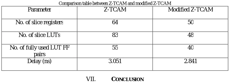
A comparison table between Z-TCAM and modified Z-TCAM is shown in Table VI. From the table, it is clear that the resource utilization of modified Z-TCAM is less than that of Z-TCAM. Also, the delay of modified Z-TCAM is lower than that of Z-TCAM.
TABLE VI
Comparison table between Z-TCAM and modified Z-TCAM
Parameter Z-TCAM Modified Z-TCAM
No. of slice registers 64 50
No. of slice LUTs 83 48
No. of fully used LUT FF pairs
55 40
Delay (ns) 3.051 2.841
VII. CONCLUSION
modifying the data mapping operation has provided an area efficient architecture for Z-TCAM. The use of parity bit in data mapping operation provide shorter propagation delay compared to Z-TCAM. Thus, the modified Z-TACM has higher area efficiency, reduced resource utilization, lower latency and higher operating speed.
REFERENCES
[1] Kostas Pagiamtzis, Ali Sheikholeslami, “ Content-Addressable Memory (CAM) Circuits and Architectures: A Tutorial and Survey", IEEE Journal of Solid-State Circuits, vol. 41, no. 3, March 2006.
[2] Banit Agrawal, Timothy Sherwood, “Ternary CAM Power and Delay Model: Extensions and Uses" , IEEE Transactions on Very Large Scale Integration (VLSI) Systems, vol. 16, no. 5, May 2008.
[3] Zahid Ullah, Manish K. Jaiswal, and Ray C. C. Cheung, “ Z-TCAM: An SRAM-based Architecture for TCAM " ,IEEE Transactions on Very Large Scale Integration (VLSI) Systems, 2014.
[4] Zahid Ullah, Manish Kumar Jaiswal, Y.C. Chan, Ray C.C. Cheung,”FPGA Implementation of SRAM-based Ternary Content Addressable Memory " , IEEE 26th International Parallel and Distributed Processing Symposium Workshops PhD Forum, 2012.
[5] Zahid Ullah, Manish Kumar Jaiswal, Ray C. C. Cheung,\”E-TCAM: An Efficient SRAM-Based Architecture for TCAM", Article in Circuits Systems and Signal Processing, April 2014.
[6] Aruna M.S, Dayananda G.K. and C. Premananda.R, “A Low Power CAM with a Auxiliary Bit " , Proc. of Int. Conf. on Recent Trends in Signal Processing, Image Processing and VLSI, 2014.
[7] Anh Tuan Do, Shoushun Chen, Zhi-Hui Kong , Kiat Seng Yeo “A Low-Power CAM with Efficient Power and Delay Trade-off " , IEEE Conference on VLSI Systems, May,2011.
[8] Mahalakshmi R, Gayathri.M, “ High Performance and Energy Efficient SRAM-based Architecture for TCAM”, International Conference on Electrical, Information and Communication Technology, March 2015.
[9] Shaly Laurence, Anuros Thomas K., “SRAM based Architecture for TCAM for Low Area and Less Power Consumption”, ARPN Journal of Engineering and Applied Sciences, vol. 10, no. 17, September 2015.
[10]Lekshmipriya S., Suby Varghese, “ FPGA Based Architecture for High Performance SRAM Based TCAM for Search Operations”, International Journal of Science and Research (IJSR), Volume 4 Issue 2, February 2015.
[11]Igor Arsovski, Trevis Chandler and Ali Sheikholeslami, “A Ternary Content-Addressable Memory (TCAM) Based on 4T Static Storage and Including a Current-Race Sensing Scheme ", IEEE Journal of Solid-State Circuits, vol. 38, no. 1, January 2003.