Analysis of Foundation System for Offshore
Wind Mill Structure
Rutuja J. Deshmukh1, Prof. S. W. Thakare 2
P.G. Student, Department of Civil Engineering, Govt. College of Engineering, Amravati, Maharashtra, India1
Associate Professor, Department of Civil Engineering, Govt. College of Engineering, Amravati, Maharashtra, India2
ABSTRACT: In recent times, bucket foundations are being considered as an alternative supporting base for offshore
wind turbines located at shallow water depths. These foundations have to resist moment and horizontal loads due to wind and wave actions. In this paper, the ultimate lateral load capacity of bucket foundation on layered sand bed is investigated numerically with finite element method. The long term effect of lateral loads, resulting from wind action and water currents acting on the wind turbine and the foundation respectively, is simulated by varying the point of application of the resultant horizontal load at several eccentricities taking the bucket foundation lid as a point of reference. It is observed that the lateral load capacity increases with foundation size and for a given foundation geometry, lateral load capacity decreases as the point of application of load is increased. From the present analysis, lateral load- overturning moment interaction diagram are developed for bucket foundation which are useful preliminary design of bucket foundation.
KEYWORDS: Wind turbine, Bucket foundation, Ultimate lateral load capacity, Lateral load - overturning moment
interaction diagram
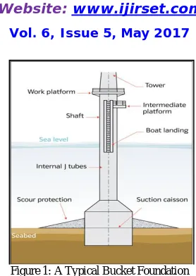
I. INTRODUCTION
Figure 1: A Typical Bucket Foundation
II.RELATEDWORK
Yuan-Zhan Wang and Xiao Zhong1 (2008) studied stability analysis for bucket foundation breakwater with finite element method. A 3D elastic-plastic finite element model was established for the stability analysis of the bucket foundation breakwater and three criterions examining the stability of the bucket foundation breakwater, which were the load-bearing capacity criterion, the load-displacement criterion, and the allowable displacement criterion, were proposed.
Khalid2 et al.( (2008) had studied the behaviour and the bearing capacity of large bucket foundations for offshore wind energy converters under horizontal and moment loading using numerical modelling. The load-deformation curves and interaction diagrams were presented for buckets with different geometries embedded in medium dense sand. They concluded that the load-moment interaction curves for the ultimate state as well as for specific deformation states could be described by nearly parallel straight lines.
Wenbai Liu3 et al.(2011) carried out the numerical simulation of pile-bucket under mono-load of up-pulling force and horizontal force was compared and analysed, then the bearing capacity of pile-bucket foundation under up-pulling and horizontal force was simulated by ABAQUS software. They concluded that the limit horizontal displacement of pile-bucket foundation increases with the increase of up-pulling load providing a limit horizontal load. The greater horizontal load is applied, the more obvious is the effect of up-pulling load increase on horizontal displacement.
Wenbai Liu4et al. (2012) analysed the displacement field and stress field of the surrounding soil of the pile-bucket foundation under the multi-cycle horizontal loading using ABAQUS software. They concluded that when the load level is small, the displacement changed little with the load increased.
Wu Ke5et al. studied the effective stress method for the vertical load and bearing capacity characteristics of bucket foundation based on ABQUS finite element program. One simulation model is established to consider the coupled effect between foundation stress fields with pore water pressure. They concluded that the change in pore water pressure distribution affects overall stability of bucket foundation under vertical load in the foundation.
W.U. Ke6 et al. (2013) studied the response of bucket foundation for combined Horizontal (H) and Moment (M) loading using FEM software ABAQUS for 3D finite element analysis. It was found that under horizontal loading or moment loading, the slope of load-displacement relation tended to vanish with increase of displacement and the imposed load sustains in a stable value.
III.NUMERICALANALYSIS
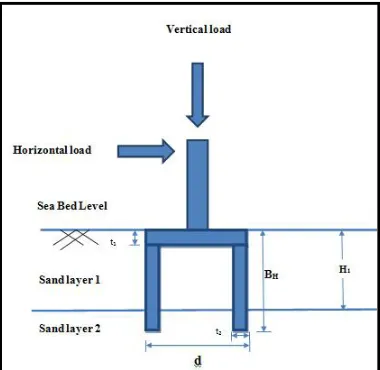
The bucket foundation was considered to be supported on the layered sand deposit with upper layer of loose sand of varying thicknesses. Vertical load (V) equal to the self-weight of structural elements and turbine was applied on the bucket foundation. Lateral load was applied at various eccentricity heights (e) above the lid. overturning moment in the model was assigned by multiplying the horizontal load with the eccentricity height above the bucket lid surface. Various thicknesses of upper loose sand layer were considered in order to investigate the influence of lateral load and moment load on the bucket behavior. Figure 2 shows cross section of bucket foundation considered for analysis, along with notations used.
Figure 2: Cross Section of Bucket Foundation Considered For Analysis.
IV.GEOMETRICDETAILSOFBUCKETFOUNDATION
Several geometries were considered in order to perform numerical analysis of bucket foundations in layered sand. In the analysis, the bucket foundation is assumed to have been already installed. Analysis was carried out for a typical 5 MW offshore wind turbine considering the self-weight load of wind turbine to be 12 MN. The geometric details and thicknesses of upper loose sand layer are given at Table 1.
Table 1: Details of Layering Thicknesses and Bucket Foundation
Parameter Values
Dimensions of bucket foundation
Top thickness of bucket t1 = 0.8 m
Bottom thickness of bucket t2 = 0.5 m
Bucket diameter D = 6 m, 8 m, 10 m Height of bucket BH = 15 m
Horizontal loading 0 – 80 MN
Vertical loading 12 MN
Type of soil and thickness of soil layer
Sand 1( loose sand ) (H1) = BH /2, (3 BH)/4, BH, 1.5
BH, 2 BH
The soil bed was considered to comprise of loose sand and dense sand. Properties of sand layers are as shown in Table 2. Model selected for analysis of bucket foundation was ‘Elastic model’ having Young’s modulus 2 x 10⁸ kN/m2, Density 78 kN/m2, Poisson’s ratio 0.5 and for soil, the model selected for analysis was ‘Drucker – Prager’ model.
Table 2: Properties assigned to soil layer for analysis.
Properties Unit weight Young’s modulus
Poisson’s ratio
Angle of internal
friction Cohesion
Symbols γ E υ Ø C
Unit kN/m3 kPa degree kPa
Loose Sand 22 30,000 0.3 33ͦ 0.05
Dense Sand 24 35,000 0.3 35ͦ 0.05
V. RESULTS AND DISCUSSION
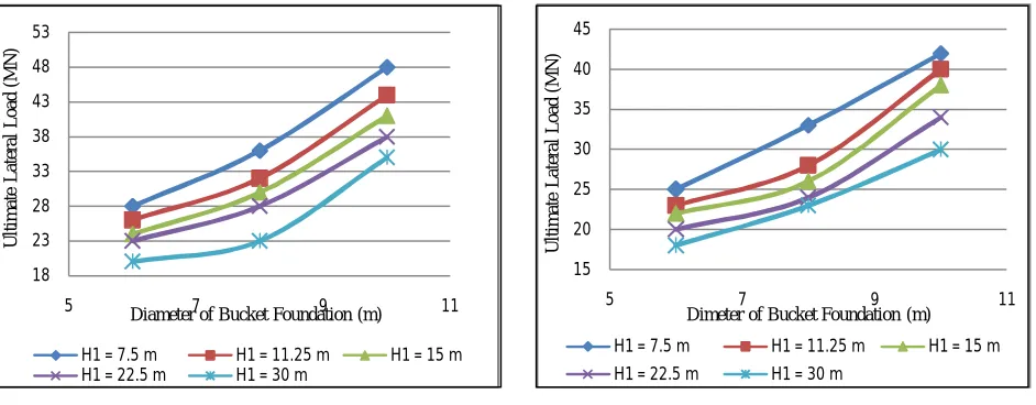
In order to explore the behaviour of bucket foundation supporting wind turbine, load combinations were varied between pure lateral loading (no eccentricity) and up to 100 m above the bucket lid. The effect of bucket diameter on lateral load capacity was studied by varying the diameter and keeping the bucket length as constant. Figures 3 to 5 show the variation of ultimate lateral load capacity with diameter of bucket foundation for various eccentricities under superstructure loads of 12 MN, and various thicknesses of upper layer of sand (H1). The main purpose of plotting
ultimate lateral load capacity curves for Bucket foundation is to determine ultimate lateral load for a bucket foundation of particular diameter.
(a) e = 0 meter (b) e = 5 meter
Figure 3(a – b): Ultimate Lateral Load Capacity of Bucket foundation in Layered Sand for Different Eccentricities 18
23 28 33 38 43 48 53
5 7 9 11
U
lt
im
a
te
L
a
te
ra
l
L
o
a
d
(M
N
)
Diameter of Bucket Foundation (m)
H1 = 7.5 m H1 = 11.25 m H1 = 15 m H1 = 22.5 m H1 = 30 m
15 20 25 30 35 40 45
5 7 9 11
U
lt
im
a
te
L
a
te
ra
l
L
o
a
d
(M
N
)
Dimeter of Bucket Foundation (m)
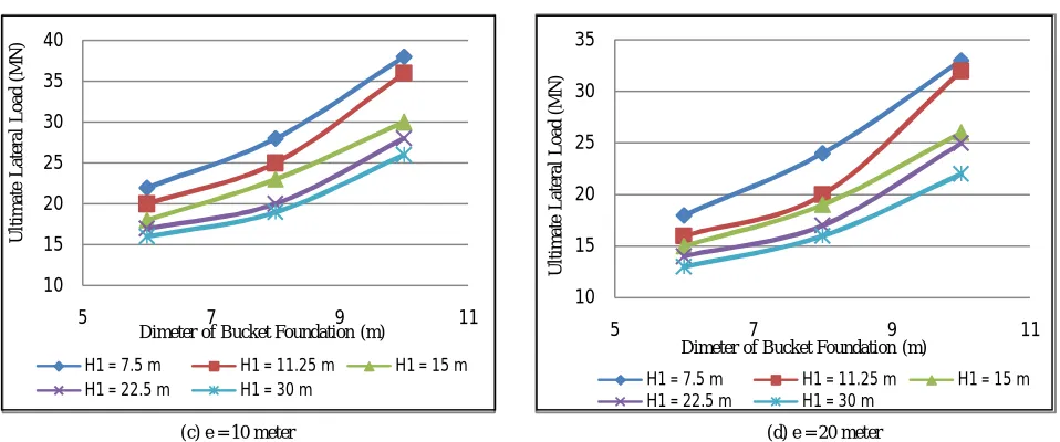
(c) e = 10 meter (d) e = 20 meter
Figure 4(c – d): Ultimate Lateral Load Capacity of Bucket foundation in Layered Sand for Different Eccentricities
(e) e = 40 meter (f) e = 80 meter
Figure 5(e – f): Ultimate Lateral Load Capacity of Bucket foundation in Layered Sand for Different Eccentricities
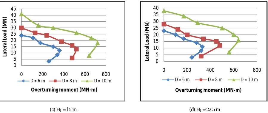
Lateral Load- overturning Moment Interaction Diagram of Bucket Foundation
The moment acting on the bucket foundation can be obtained from the Lateral load and the respective eccentricity. For any geometry of bucket foundation and different thickness of upper loose sand layer, a lateral load- overturning moment interaction diagram can be constructed. The interaction diagram consists of several plots between lateral load and moment corresponding to failure condition. Any combination of lateral load and overturning moment, located outside the envelope of respective Bucket geometry, will cause instability of Bucket foundation. In that case, the next larger geometry can be selected in a step wise manner till the stability requirement is fulfilled. Figure 6 to 8 shows the
10 15 20 25 30 35 40
5 7 9 11
U lt im a te L a te ra l L o a d (M N )
Dimeter of Bucket Foundation (m)
H1 = 7.5 m H1 = 11.25 m H1 = 15 m H1 = 22.5 m H1 = 30 m
10 15 20 25 30 35
5 7 9 11
U lt im a te L a te ra l L o a d (M N )
Dimeter of Bucket Foundation (m)
H1 = 7.5 m H1 = 11.25 m H1 = 15 m H1 = 22.5 m H1 = 30 m
5 10 15 20 25
5 7 9 11
U lt im a te L a te ra l L o a d (M N )
Dimeter of Bucket Foundation (m)
H1 = 7.5 m H1 = 11.25 m H1 = 15 m H1 = 22.5 m H1 = 30 m
0 2 4 6 8 10 12
5 7 9 11
U lt im a te L a te ra l L o a d (M N )
lateral load- overturning moment interaction diagram with diameter of bucket foundation with respect to varying upper loose sand layer thickness under superstructure loads of 12 MN.
(a) H1 = 7.5 m (b) H1 = 11.25 m
Figure 6 (a - b): Lateral Load - Overturning Moment Interaction Curve for Bucket Foundation for Various Depth of Loose Sand Layer
(c) H1 = 15 m (d) H1 = 22.5 m
Figure 7 (c – d): Lateral Load - Overturning Moment Interaction Curve for Bucket Foundation for Various Depth of Loose Sand Layer 0
10 20 30 40 50 60
0 500 1000
La
te
ra
l L
o
a
d
(
M
N
)
Overturning moment (MN-m)
D = 6 m D = 8 m D = 10 m
0 10 20 30 40 50
0 500 1000
La
te
ra
l L
o
a
d
(
M
N
)
Overturning moment (MN-m)
D = 6 m D = 8 m D = 10 m
0 5 10 15 20 25 30 35 40 45
0 200 400 600 800
La
te
ra
l L
o
ad
(
M
N
)
Overturning moment (MN-m) D = 6 m D = 8 m D = 10 m
0 5 10 15 20 25 30 35 40
0 200 400 600 800
La
te
ra
l L
o
ad
(
M
N
)
Figure 8: Lateral Load - Overturning Moment Interaction Curve for Bucket Foundation (H1 = 30 m)
VI. CONCLUSIONS
Bucket Foundation for offshore windmill structures have been analysed using MIDAS GTS 3D. Behaviour of Bucket foundation has been studied in layered sand bed considering different parameters. From the present study, following conclusions are drawn.
1. Lateral load capacity of Bucket foundation in case of layered sand bed decreases with increase in depth of upper loose sand layer
2. In case of multilayer sand bed, the effect of lower dense sand layer diminishes when the depth of upper loose sand layer becomes greater than 10 – 15 m below the bottom of Bucket foundation.
3. The lateral load overturning moment interaction diagram developed for Bucket foundation enables a selection of the required geometry of Bucket foundation for preliminary design.
4. From the ultimate lateral load capacity layered sand bed, ultimate lateral load capacity can be evaluated for preliminary design of Bucket foundation.
REFERENCES
1. Yihua Wanga, Xiaobing Lua, Shuyun Wanga and Zhongmin Shi (2005), “The response of bucket foundation under horizontal dynamic loading”, Ocean Engineering 33, pp 964–973.
2. Yuan-Zhan Wang and Xiao Zhong (2008), “Stability Analysis for Bucket Foundation Breakwater with Finite Element Method”, Chinese-German Joint Symposium on Hydraulic and Ocean Engineering. pp 108-110.
3. Khalid Abdel-Rahman and Martin Achmus (2009), “Numerical Investigations on the Bearing Capacity of Bucket Foundations Under Combined Horizontal and Moment Loading”, University of Hannover, Institute of Soil Mechanics, Foundation Engineering and Waterpower Engineering, Hannover, Germany.
4. Xiaobing Lu, Xuhui Zhang and Shuyun Wang (2010), “Dynamic Responses of Bucket Foundations”, The Open Ocean Engineering Journal, pp 18-20.
5. Barari A.,Ibsen L.B (2011), “Effect of Embedment on the Vertical Bearing Capacity of Bucket Foundations in Clay”, Pan-Am geotechnical conference.
6. Wu Ke and Sun Yue (2012), “Effective Stress Method on Bearing Capacity of Bucket Foundation Subjected to Vertical Loading”, EJGE, Vol.17, pp 2027-2034.
7. Wu. Ke and Mingyue M.A. (2013), “Analysis of Bearing Capacity of Suction Bucket Foundation Subjected to Horizontal and Moment Loadings” Research Journal of Applied Sciences, Engineering and Technology 6(8): 1479-1482.
0 5 10 15 20 25 30 35 40
0 200 400 600
La
te
ra
l L
o
a
d
(
M
N
)
Overturning moment (MN-m)