ISSN(Online): 2319-8753 ISSN (Print): 2347-6710
I
nternational
J
ournal of
I
nnovative
R
esearch in
S
cience,
E
ngineering and
T
echnology
(A High Impact Factor, Monthly, Peer Reviewed Journal) Visit: www.ijirset.com
Vol. 6, Issue 10, October 2017
Computational Fluid Dynamic Analysis of Gas
Solid Fluidization
Ruman Singh1, Saurabh Kumar2, Arjun Kundu3, Sarfraj ahmed4
M. E Student, Department of Mechanical Engineering, RITEE Raipur, India1
Associate Professor, Department of Mechanical Engineering, RITEE Raipur, India2
Asst. Professor, Department of Mechanical Engg, Rungta Engg. College Bhilai, India3
Asst. Professor, Department of Mechanical Engg, RSR Bhilai, India4
ABSTRACT: Fluidization is a process in which fluid under pressure passes through the particulate substance at higher velocity so that it can lift the particles and particles can flow along with the fluid. The present work gas solid fluidization is aimed at analyzing the effect of density of material, size of material, air flow rate on pressure drop. The computational fluid dynamic analysis was carried out using ANSYS ICEM. It has been found that the pressure drop is higher for high density material as compare to lower density material. throughout the process with increase in air velocity.
KEYWORDS: Computational fluid dynamics, cylindrical bed, solid (coal and concrete)-gas(Air)
I. INTRODUCTION
A fluidized bed is a physical phenomenon occurring when a quantity of a solid particulate substance (usually present in a holding vessel) is placed under appropriate conditions to cause a solid/fluid mixture to behave as a fluid. This is usually achieved by the introduction of pressurized fluid through the particulate medium.[1-3] This results in the medium then having many properties and characteristics of normal fluids, such as the ability to free-flow under gravity, or to be pumped using fluid type technologies.
The resulting phenomenon is called fluidization.[4] Fluidized beds are used for several purposes, such as fluidized bed reactors (types of chemical reactors), fluid catalytic cracking, fluidized bed combustion, heat or mass transfer or interface modification, such as applying a coating onto solid items.[5-7] This technique is also becoming more common in aquaculture for the production of shellfish in integrated multi-trophic aquaculture systems.[8-10]
II. METHODOLOGY
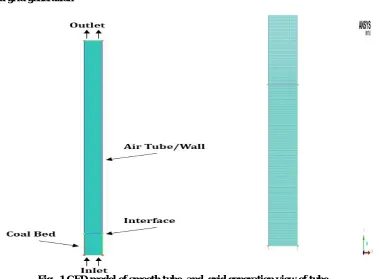
2.1 Modelling and grid generation
ISSN(Online): 2319-8753 ISSN (Print): 2347-6710
I
nternational
J
ournal of
I
nnovative
R
esearch in
S
cience,
E
ngineering and
T
echnology
(A High Impact Factor, Monthly, Peer Reviewed Journal) Visit: www.ijirset.com
Vol. 6, Issue 10, October 2017
2.2 Model and grid generation
Fig. 1 CFD model of smooth tube and grid generation view of tube.
2.3 Numerical analysis
ANSYS fluent has been used to obtain flow solution. The following boundary conditions were imposed:
2.3.1 Velocity inlet: The inlet of the computational domain has been defined as velocity inlet where different values of velocity has been specified.
2.3.2 Pressure outlet: The outlet of the domain has been defined as a pressure outlet where atmospheric pressure of 101325 pa has been specified.
2.3.3 Adiabtic walls: The walls of the tube has been defined as no slip adiabtic walls.
Realizable k-ε turbulence model has been used to provide for turbulence closure. Turbulence intesnity of 5 % and a ratio of 10 % has been specified.
Implicit Eulerian model has been used to solve for multiphase flow. Where granualar visocity has been computed using syamlal-obrein model. And drag on the particles have also been compouted using syamlal-obrein model.
Table 1 Scope of the experiment
S. No Bed material Particle size dp (mm)
Particles density (kg/m3)
Static bed height(m)
01 Coal 2.0,4.0 1200 0.1
ISSN(Online): 2319-8753 ISSN (Print): 2347-6710
I
nternational
J
ournal of
I
nnovative
R
esearch in
S
cience,
E
ngineering and
T
echnology
(A High Impact Factor, Monthly, Peer Reviewed Journal) Visit: www.ijirset.com
Vol. 6, Issue 10, October 2017
Table 2 CFD simulation parameters (For coal and concrete stone)
S. No
Description Coal Particle Concrete Stone Particle
Value Comment Value Comment
01 Particle density, ρp ,(
kg/m3 )
1200 Coal 1700 Concrete Stone
02 Gas density, ρg ,( kg/m3 ) 1.225 Air 1.225 Air
03 Mean particle diameter, dp, (mm)
2.0,4.0 Uniform distribution 2.0 Uniform distribution 04 Gas velocity, U, (m/s) 0.75,1.0 and1.25 - 0.75,1.0 and
1.25
-
05 Bed width, (m) 0.05 Fixed value 0.05 Fixed value
06 Bed height,( m) 1.0 Fixed value 1.0 Fixed value
07 Static bed height, ( m) 0.1 Fixed value 0.1 Fixed value
08 Inlet Boundary Condition Velocity Gas velocity Velocity Gas velocity
09 Outlet Boundary Condition
Pressure Fully developed flow
Pressure Fully developed
flow
10 Specific Heat Cp(J/kg-k) 1349 - 750 -
11 Thermal Conductivity K (W/m-k)
158.62 - 1.7 -
12 Operating Pressure (Pa) 101325 - 101325 -
Table 4 Properties of gas (Air)
Density, ρ 1.225 kg/m3
Specific Heat Capacity, Cp 1006.43 J/kg K
Thermal Conductivity, k 0.0242 W/m K Viscosity, µ 1.7894×10⁻⁵ kg/m s
III. RESULTS & DISCUSSION
3.1 Result obtained from analysis
A gas -solid fluidized bed of width 0.05 m and height 1.0 m has been simulated using
ISSN(Online): 2319-8753 ISSN (Print): 2347-6710
I
nternational
J
ournal of
I
nnovative
R
esearch in
S
cience,
E
ngineering and
T
echnology
(A High Impact Factor, Monthly, Peer Reviewed Journal) Visit: www.ijirset.com
Vol. 6, Issue 10, October 2017
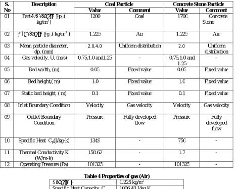
Figure 2Contours of volume fraction of coal (size 2mm) at air velocity 0.75 m/s for initial bed height of 0.1 m (10 cm) and time vary from 0,0.1,0.2,0.3,0.4,0.5,0.6,0.7,0.8,0.9 and 1.0 sec
ISSN(Online): 2319-8753 ISSN (Print): 2347-6710
I
nternational
J
ournal of
I
nnovative
R
esearch in
S
cience,
E
ngineering and
T
echnology
(A High Impact Factor, Monthly, Peer Reviewed Journal) Visit: www.ijirset.com
Vol. 6, Issue 10, October 2017
Figure 4Contours of volume fraction of coal (size 2mm) at air velocity 1.25 m/s for initial bed height of 0.1 m (10 cm) and time from 0,0.1,0.2,0.3,0.4,0.5,0.6,0.7,0.8,0.9 and 1.0 sec
Figure 5Contours of volume fraction of coal (size 4mm) at air velocity 1.0 m/s , for initial bed height of 0.1 m (10 cm) and time from 0,0.1,0.2,0.3,0.4,0.5,0.6,0.7,0.8,0.9 and 1.0 sec
ISSN(Online): 2319-8753 ISSN (Print): 2347-6710
I
nternational
J
ournal of
I
nnovative
R
esearch in
S
cience,
E
ngineering and
T
echnology
(A High Impact Factor, Monthly, Peer Reviewed Journal) Visit: www.ijirset.com
Vol. 6, Issue 10, October 2017
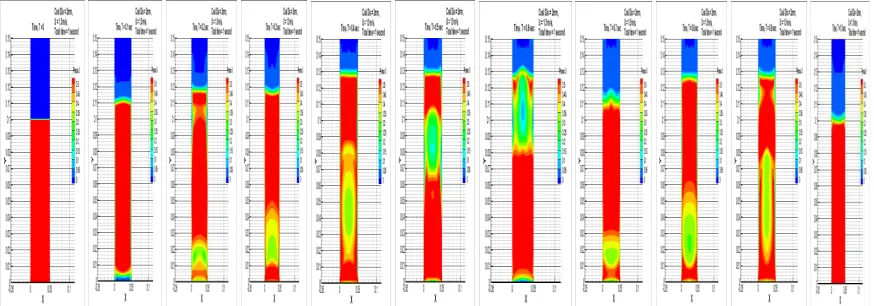
From the figure 2,3,4,5,6 it is very much clear when coal particle weight and drag force due to friction are balanced than coal particle are suspended in air and behave like fluid. This fluidization phenomenon is shown at time 0 to 1.0 sec.
Figure 7Contours of volume fraction of concrete stone (size 2mm) at air velocity of 0.75m/s , for initial bed height of 0.1 m (10 cm) and time from 0,0.1,0.2,0.3,0.4,0.5,0.6,0.7,0.8,0.9 and 1.0 sec.
ISSN(Online): 2319-8753 ISSN (Print): 2347-6710
I
nternational
J
ournal of
I
nnovative
R
esearch in
S
cience,
E
ngineering and
T
echnology
(A High Impact Factor, Monthly, Peer Reviewed Journal) Visit: www.ijirset.com
Vol. 6, Issue 10, October 2017
Figure 9 Contours of volume fraction of concrete stone (size 2mm) at air velocity of 1.25m/s , for initial bed height of 0.1 m (10 cm) and time vary from 0,0.2,0.4,0.6,0.8,1.0,1.2,1.4,1.6,1.8 and 2.0sec
Table 5 Result obtained for pressure drop
Velocity (m/s)
Pressure drop (Pa)
Coal(2mm) Coal (4mm) Concrete Stone (2mm)
U = 0.75 815.10 - 1003.83 U = 1.0 886.16 760.95 1143.28 U = 1.25 1026.82 848.12 1232.41 .
3.3 Pressure drop
815.1 886.16
1026.82 1003.83
1143.28
1232.41
400 600 800 1000 1200 1400
0 0.2 0.4 0.6 0.8 1 1.2 1.4
d
e
l_
p
(P
a)
Gas Velcity(m/s)
ISSN(Online): 2319-8753 ISSN (Print): 2347-6710
I
nternational
J
ournal of
I
nnovative
R
esearch in
S
cience,
E
ngineering and
T
echnology
(A High Impact Factor, Monthly, Peer Reviewed Journal) Visit: www.ijirset.com
Vol. 6, Issue 10, October 2017
In above figure shown bed pressure drop vs gas velocity. It is clear from the above graph bed pressure drop of concrete stone is higher than the coal material at different air velocity 0.75,1.0 and 1.25m/s for the same size of material 2.0 mm.
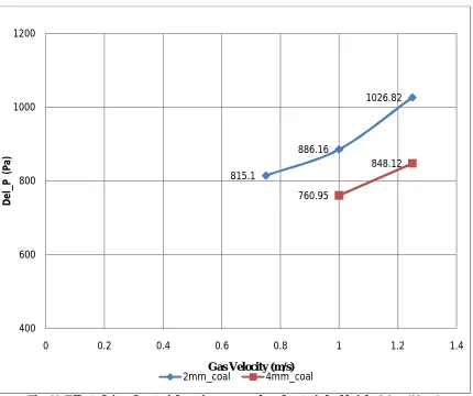
Fig. 11 Effect of size of material on air pressure drop for static bed height 0.1 m (10 cm)
In above fig 11 graph plotted between pressure drop and gas velocity for coal material, size 2mm and 4mm.The graph is shown effect of size of material of coal air pressure drop for static bed height 0.1 m. It is clear shown in graph, 2 mm size of coal material pressure drop is higher as compare to 4mm size of coal material.
IV. CONCLUSION
Computational fluid dynamic (CFD) work has been carried out to study the analysis of gas solid fluidization .The influences of several system parameters i.e. density of material, size of material, flow rate of air on the bed pressure drop were studied.CFD result are shown in various figure and result value are plotted on the graph pressure drop vs gas velocity. The following conclusion are obtained by the graph.
.
(i) Air pressure drop in a gas solid fluidization system system is more for high density material (concrete stone). as compare to lower density material (coal).
815.1
886.16
1026.82
760.95
848.12
400 600 800 1000 1200
0 0.2 0.4 0.6 0.8 1 1.2 1.4
D
e
l_
P
(
P
a)
Gas Velocity (m/s)
ISSN(Online): 2319-8753 ISSN (Print): 2347-6710
I
nternational
J
ournal of
I
nnovative
R
esearch in
S
cience,
E
ngineering and
T
echnology
(A High Impact Factor, Monthly, Peer Reviewed Journal) Visit: www.ijirset.com
Vol. 6, Issue 10, October 2017
(ii) Air pressure drop in a gas solid fluidization system doesn’t follow the same pattern for both material coal and concrete stone.
(iii) Air pressure drop in a gas solid fluidization system increases with respect to gas velocity (0.75,1.0 and 1.25m/s) for both material coal and concrete stone
(iv) Air pressure drop value is lower for 4 mm coal material as compare 2 mm coal material.
REFERENCES
[1] A. Sahoo, Ch. Ramesh and K. C. Biswal, Experimental and computational study of the bed dynamics of semi cylindrical gas - solid fluidized bed canadian journal of chemical engineering.
[2] Tang Lingang (2017), Characteristics of fluidization and dry-beneficiation of a wide-size-range medium-solids fluidized bed, IJMST.
[3] Apurv Kumar , Peter Hodgson, Daniel Fabijanic1, Weimin Gao, and Subrat Das ,Analytical model to locate the fluidization interface in a solid-gas vacuum fluidized bed.
[4] Yan-qin Li , John R. Grace , R. Bhushan Gopaluni , Hsiaotao Bi , C. Jim Lim , Naoko Ellis (2011), Characterization of gas–solid fluidization: A comparative study of acoustic and pressure signals, Pg. 200–210.
[5] Yuping Liu ,Hiroaki Ohara , Atsushi Tsutsumi (2016) Pulsation-assisted fluidized bed for the fluidization of easily agglomerated particles with wide size distributions powder technology.
[6] Yong Jiang, Zengqiang Chen , Huannan Shao, Yuemin Zhao, Zhenfu Luo, Mingbing Tan, Jingfeng He,Fusheng Liu, Pu Hong (2016) ,The effect of a porous medium on fluidization characteristics in air dense medium fluidized bed.
[7] Awadhesh Kumarand Gopendra K. Roy 2007, Bed dynamics of gas-solid fluidized bed with rod promoter china particuology volume 5, issue 4, 2007, pages 261-266.
[8] LijuanDeng, YaningLiu, Wei Wang, JinghaiLi (2013) A two-fluid smoothed particle hydrodynamics (TF-SPH) method for gas–solid fluidization, chemical engineering science.
[9] Emma Ireland, Kate Pitt and Rachel Smith (2016) A review of pulsed flow fluidization; the effects of intermittent gas flow on fluidized gas-solid bed behavior Elsevier.