Design and Optimization of Power and
Process, Refrigeration and Oil Piping with
Respect To the Failures of Piping by Final
Run, Weight Run and Thermal Run
Iyer Rahul Rajesh1, Ezhil Vannan.T2, Gopalakrishnan.P3, Jayadevan.G4, Chandramouli.M5
B.E. Student, Department of Mechanical Engineering, TRP Engineering College (SRM Group), Irungalur,
Tiruchirapalli, Tamil Nadu, India1, 2, 3, 4, 5
ABSTRACT:The work is to optimize the types and number of hangers and restraints of the piping layout by
classifying the various piping as thermal run, weight run, and final run using CAESAR-II. The geometrical properties such as diameter, thickness, and span length were kept constant during the design and analysis of the piping layout. The type of restraint is optimized by studying the report of each type of piping namely thermal-run, weight-run, and final-run. The variation of the pipe material density with respect to the change of pressure and temperature of the operating medium, which leads to the linear and lateral deformation and stress development in the piping, was used to vary the type of restraint between the supports. The number of supports is optimized by the CAESAR-II, and STADD-PRO reports. The material chosen is verified by the ASME (SECTION II) formula and X-STEEL package.
KEYWORDS: Thermal run, Weight run, Final run, Operating Medium, Pressure, Temperature, CAESAR-II.
I. INTRODUCTION
Piping is the engineering related to a structure which transfers a vast amount of fluid from one place to another through pipes made of alloy steel, non-ferrous alloys or composites. The transferring pipe carrying the fluid is subjected to many loads such as thermal load, shock load due to bend or mixing, structural load or it may be loaded due to the fluid density. The parameters involved in the piping engineering (other than the pipe dimensions) are material properties of the pipe, fluid pressure, temperature and density, flow properties of the fluid, all types of loading acting on the pipe and fluid, number and type of supports and restraints provided to the piping.
II. PROBLEMDEFINITION
The failures occurring in various piping can be classified as: 1. Failure by Thermal-Run
2. Failure by Weight-Run 3. Failure by Final-Run
The thermal-run is the piping which fails due to thermal load acted on the pipeline by the fluid. The flow of the fluid in a thermal run piping will be one dimensional, and the temperature of the flowing media is higher than the atmospheric temperature due to the increase in fluid velocity through bends in piping leading to rising in temperature by the fluid collision. Such piping is common in all petrochemical, oil and gas industries where diameter, thickness and insulation thickness of the piping is very low compared to the length of piping. Also, the thermal conductivity of the piping is very high compared to the tensile strength and Young's modulus.
structure. The flow will be lateral and transverse in direction. A weight run failure may be observed as the cracking at the supports due to overloading the piping. Weight run piping is common in refrigeration piping.
The Final run-piping is the one which may fail due to any of the reasons mentioned above, i.e., thermal load or weight or both. In final-run piping, there will be three-dimensional fluid flows in lateral, linear and transverse directions. Therefore final run piping is found in process industries and power industries.
III. DESIGN STEPS FOR PIPING
Any piping design involves the following processes in general:
(i) The first step is the material selection. The material for the required piping is selected with the help of X-STEEL software. Also, the ASME Section II provides a formula for calculating the ultimate strength of steels,
a. For carbon steel,
Ultimate tensile strength= 19.1[15.4+ (1.8%Mn) + (5.4%Si) + (0.25%pearlite) + (0.5d1/2)] (Where d is the grain diameter of the material)
b. For alloy steel,
Ultimate tensile strength= 90 + 1000[(%C) + (45%Mn) + (75%Si) + (31%Cr) + (30%Ni)] Thus the material selection is assured with help of X-STEEL software and ASME (SECTION II) formula.
(ii) The next step is the piping design. For this step, CAESAR-II software is used. CAESAR-II is the software which enables the design and analysis of systems with more number of elements having a very high length w.r.to cross-section. Hence it is preferred for piping design and analysis. For study purpose the version has some restrictions, so the dimensions of piping are 114mm diameter, 4.5mm thick (for oil piping) and 9.5mm thick (for power and process piping). Also, for study version, the number of routings is limited with 20.
(iii)The third step is piping design for supports. Based on the given piping diagram a piping engineer optimizes the location of the supports using STADD-PRO software so that no excess money is wasted by providing unwanted supports. This software is used to find the ideal place to fix the supports, i.e., the points where excess/failure load acts. Thus the determination of an ideal number of supports is proved by STADD-PRO software.
(iv)The final step is to prove the selection of welding method. For this, ANSYS 14.5, well-known software for analysis, is used. From the ANSYS report if any welding defects were found, then it should be rectified. For hot cracking defect, uniform heating with asbestos sheet on top is employed; For loss of alloying element while welding, stabilizing elements like Ti, Zr, Nb and Be are added along with welding rod; For shrinkage defect, hammering and peening should be done once in 400 mm of the weld; While welding copper, Si and Ph are to be added to avoid oxidation of Cu. Also, a preheating of the weld zone to 150-2000C is recommended for welding Cu and Cu alloys.
Thus, in the piping design, each and every process is proved and satisfied to the client and then only fabricated.
IV. SOLUTION TO THE PROBLEM
IV.I. THERMAL RUN
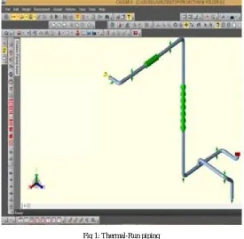
For the thermal run failure, an expansion joint is provided along the length of the piping, and no anchor is provided on the route where the expansion joint is provided. If in the route of the expansion joint, an anchor is provided, then its expansion will be arrested by the anchor and thereby the pipe crack and fail. An expansion joint is the sub-element of the route which is a different material than that of the piping. Normally low thermal expansion and high thermal conducting material like copper and its alloys in the form of bellow tube act as the expansion joint. Its selection is verified by CAESAR-II. Further, restraints like Y, +Y, GUIDE, etc. are provided to withstand the weight of piping and the fluid. Depending upon the load acting on the piping, the choice of restraint is made. Nozzle and anchor should be provided only at the end of piping, if required.
image is used for support notation, a square plate for anchor and green or yellow bellow like an image for expansion joint.
Fig 1: Thermal-Run piping
For the above pipe routing, the report was obtained, and the results are satisfactorily found to be ok and the CAESAR-II report is shown below.
TABLE 1: Thermal-Run report
Node DX in. DY in. DZ in. RX deg. RY
deg. RZ deg.
10 0 0 0 0 0 0
20 0 0.0022 0 0 0 0
28 0 0.0124 -0.0002 -0.0006 0 0
29 0 0.0876 -0.019 -0.0975 0 0
30 0 0.1846 0.0022 -0.0894 0 0
38 0 0 0.0046 -0.893 0 0
39 0 0 0.0655 0.0072 0 0
40 0 0 0.0379 0.1188 0 0
48 0 0 -0.2384 0.1168 0 0
49 0 0 -0.2455 -0.0479 0 0
50 0 0 -01651 -0.1366 0 0
55 0 0 -01502 -0.1364 0 0
58 0 0 -0.0931 -0.1348 0 0
59 0 0 -00192 -0.0384 0 0
60 0 0 0.0068 0.0053 0 0
70 0 0 0 0 0 0
IV.II. WEIGHT RUN
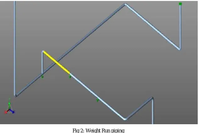
For weight run piping, we have to reduce the various displacements, forces and moments, acting on the piping due to either fluid movement or the weight of fluid and piping. So restraints and anchors are the best suitable for weight run piping. Common restraints available in CAESAR-II for weight run piping are X, Y, Z, +X, +Y, +Z, 2X, 2Y, 2Z, X/2, Y/2, Z/2 (where X, Y, and Z denote the direction to be arrested) and anchor. The support location is optimized using both STADD-PRO and CAESAR-II. For weight run piping showed below, the pipe code is B31.5 Refrigeration piping, and the material is SA 213 TP 301.
Fig 2: Weight Run piping
To reduce bend in very long piping horizontal and vertical guides may also be used. The CAESAR-II report for the above weight run piping is as below:
TABLE 2: Weight Run report
Node fx N fy N fz N mx
N.m my N.m mzN.m
12 61 -208 -1982 471 -3835 -356
14 61 -208 1783 471 5364 437
14 4540 165 5 95 21 -528
25 122 -65 -1621 545 -3025 -137
198 -2065 -166 -5 -95 -59 1770
210 -165 5 -2175 -60 -2677 30
220 -10595 -165 5 30 71 1547
298 -2063 -164 2 37 61 1755
299 -1547 -2 1315 70 -1682 18
300 -164 -2 1984 62 -1473 -36
310 -164 -2 -2176 62 -2677 -13
320 -10597 -164 -2 -13 14 1491
Only at two nodes namely 220 and 320, there is a high force of about 10600N in the negative X direction which is rectified by providing a ‘+X’ restraint.
IV.III. FINAL RUN
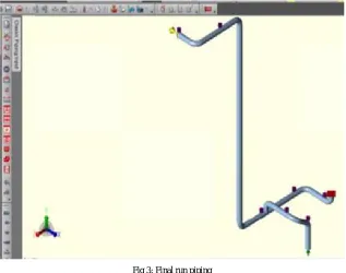
(obtained from STADD-PRO and CAESAR-II reports) and thereby reduce piping stresses. For the final run piping, the piping code is B31.1 Power piping (Boiler), and Process piping and the material chosen is alloy steel: SA 335 P22.
Fig 3: Final run piping
In the above piping, the hanger is indicated by the violet colour spring like image (Standard notation for hanger in CAESAR-II). For final run piping we have to get three reports namely stresses, local element forces and the displacements, since we have to make the piping ok by reducing all the three values to a negligible value.
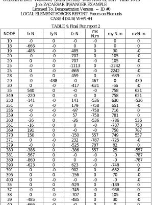
CAESAR II 2011 Ver.5.30.0, (Build 101122) Date: AUG 31, 2017 Time: 16:13 Job: Z:\CAESAR II\HANGER EXAMPLE
Licensed To: Demonstration Version -- ID #0 LOCAL ELEMENT FORCES REPORT: Forces on Elements
CASE 4 (SUS) W+P1+H
TABLE 3: Final Run report 1
NODE DX mm DY mm DZ mm RX
deg. RY deg. RZ deg.
10 -89.406 -4.154 0.000 0.1902 -0.0001 -0.2853
NODE DX mm DY mm DZ mm deg. RX RY deg. RZ deg.
355 -61.255 -0.000 0.738 0.7212 0.0350 -1.6933
359 -61.255 17.941 1.103 0.7926 0.0350 -1.7479
360 -59.857 21.292 1.807 0.8169 0.0525 -1.8198
361 -56.362 22.729 3.446 0.8764 0.0701 -1.8919
369 -15.707 22.729 22.872 0.9862 0.0701 -2.0060 370 -11.921 23.534 24.789 1.0553 0.0519 -2.0678 371 -10.376 25.586 25.629 1.1230 0.0336 -2.0930 379 -11.371 60.500 25.629 1.2144 0.0336 -2.3034 380 -13.251 62.790 24.680 1.2192 0.0519 -2.3286 381 -17.734 63.740 22.385 1.2199 0.0701 -2.3904 389 -90.852 63.744 -13.709 1.2199 0.0701 -2.5522 390 -95.716 65.770 -15.949 1.2199 0.0701 -2.6232 391 -97.778 70.770 -16.767 1.2199 0.0701 -2.6876 395 -97.778 106.099 -15.853 1.2199 0.0701 -2.7147 400 -97.778 148.711 -14.751 1.2199 0.0701 -2.7122
CAESAR II 2011 Ver.5.30.0, (Build 101122) Date: AUG 31, 2017 Time: 16:13 Job: Z:\CAESAR II\HANGER EXAMPLE
Licensed To: Demonstration Version -- ID #0 LOCAL ELEMENT FORCES REPORT: Forces on Elements
CASE 4 (SUS) W+P1+H
TABLE 4: Final Run report 2
NODE fx N fy N fz N mx
N.m my N.m mzN.m
10 -0 0 -0 -0 0 0
18 -666 -0 0 0 0 0
19 -485 -0 485 0 30 -0
20 -0 -0 707 0 105 -0
20 0 -0 707 -0 105 -0
25 -0 0 -1113 0 -2242 0
25 0 -0 -865 -0 2242 -0
28 -0 0 459 0 -689 0
29 -0 438 -0 467 0 439
30 0 -0 -417 -621 -66 -0
35 540 0 -0 -0 758 621
349 -220 0 -0 0 758 621
350 -141 -0 141 -536 630 -536
351 -0 -0 179 -758 651 -0
355 -0 -0 -97 -758 716 0
359 -0 -0 57 -758 781 0
360 -26 0 -26 -536 -786 536
361 -16 0 0 -0 -787 758
369 191 0 -0 -0 758 787
370 150 0 -150 557 749 557
371 0 -0 232 -787 -725 -0
379 -0 0 -525 787 82 0
380 -386 0 -386 557 25 -557
381 -567 0 -0 -0 -0 -787
389 -860 0 0 -0 -0 -787
390 -623 0 623 -0 -748 0
391 0 -0 902 0 -652 -0
395 0 0 -156 0 70 -0
400 0 -0 -0 -0 -0 -0
35 0 0 -529 0 -189 0
37 -0 0 -745 -0 -986 0
38 0 -0 -707 0 105 -0
39 -485 -0 -485 0 30 -0
NODE fx N fy N fz N N.m mx my N.m mzN.m
50 0 0 0 0 0 0
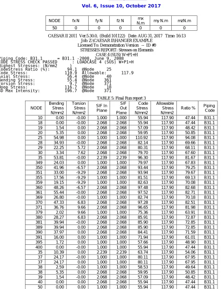
CAESAR II 2011 Ver.5.30.0, (Build 101122) Date: AUG 31, 2017 Time: 16:13 Job: Z:\CAESAR II\HANGER EXAMPLE
Licensed To: Demonstration Version -- ID #0 STRESSES REPORT: Stresses on Elements
CASE 4 (SUS) W+P1+H
Piping Code: B31.1 = B31.1 -2008, June 9, 2008 CODE STRESS CHECK PASSED : LOADCASE 4 (SUS) W+P1+H Highest Stresses: (N/mm2 )
CodeStress Ratio (%): 94.1 @Node 25
Code Stress: 110.9 Allowable: 117.9 Axial Stress: 56.4 @Node 40
Bending Stress: 55.4 @Node 361 Torsion Stress: 9.7 @Node 371 Hoop Stress: 116.7 @Node 18 3D Max Intensity: 196.7 @Node 371
TABLE 5: Final Run report 3
NODE Bending Stress N/mm2 Torsion Stress N/mm2 SIF In Plane SIF Out Plane Code Stress N/mm2 Allowable Stress N/mm2
Ratio % Piping Code
10 0.00 -0.00 1.000 1.000 55.94 117.90 47.44 B31.1
18 0.00 -0.00 2.068 2.068 55.94 117.90 47.44 B31.1
19 1.54 0.00 2.068 2.068 57.09 117.90 48.42 B31.1
20 5.35 0.00 2.068 2.068 59.95 117.90 50.85 B31.1
25 54.98 0.00 1.000 1.000 110.92 117.90 94.08 B31.1
28 34.93 -0.00 2.068 2.068 82.14 117.90 69.66 B31.1
29 22.25 5.72 2.068 2.068 80.31 117.90 68.11 B31.1
30 3.34 7.62 2.068 2.068 79.70 117.90 67.60 B31.1
35 53.81 -0.00 2.239 2.239 96.30 117.90 81.67 B31.1
349 24.03 0.00 1.000 1.000 79.97 117.90 67.83 B31.1
350 41.96 -6.57 2.068 2.068 93.44 117.90 79.25 B31.1
351 33.00 -9.29 2.068 2.068 93.94 117.90 79.67 B31.1
355 17.56 -9.29 1.000 1.000 81.51 117.90 69.13 B31.1
359 19.15 -9.29 1.000 1.000 82.63 117.90 70.08 B31.1
360 48.26 -6.57 2.068 2.068 97.48 117.90 82.68 B31.1
361 55.44 -0.00 2.068 2.068 97.52 117.90 82.71 B31.1
369 26.80 -0.00 1.000 1.000 82.74 117.90 70.18 B31.1
370 47.33 6.83 2.068 2.068 97.28 117.90 82.51 B31.1
371 36.76 9.66 2.068 2.068 96.65 117.90 81.98 B31.1
379 2.02 9.66 1.000 1.000 75.36 117.90 63.91 B31.1
380 28.27 6.83 2.068 2.068 85.91 117.90 72.87 B31.1
381 39.94 -0.00 2.068 2.068 85.90 117.90 72.85 B31.1
389 39.94 0.00 2.068 2.068 85.90 117.90 72.85 B31.1
390 37.97 0.00 2.068 2.068 84.41 117.90 71.59 B31.1
391 16.00 0.00 1.000 1.000 71.94 117.90 61.01 B31.1
395 1.72 0.00 1.000 1.000 57.66 117.90 48.90 B31.1
400 0.00 -0.00 1.000 1.000 55.94 117.90 47.44 B31.1
35 10.39 0.00 2.239 2.239 63.74 117.90 54.06 B31.1
37 24.17 -0.00 1.000 1.000 80.11 117.90 67.95 B31.1
37 24.17 0.00 1.000 1.000 80.11 117.90 67.95 B31.1
38 2.59 -0.00 1.000 1.000 58.53 117.90 49.64 B31.1
38 5.35 0.00 2.068 2.068 59.95 117.90 50.85 B31.1
39 1.54 -0.00 2.068 2.068 57.09 117.90 48.42 B31.1
40 0.00 0.00 2.068 2.068 55.94 117.90 47.44 B31.1
50 0.00 0.00 1.000 1.000 55.94 117.90 47.44 B31.1
Thus with the help of hanger, the stress is far reduced than the allowable stress value as evident from the above CAESAR-II report, and the piping is made completely ok for manufacturing.
V.CONCLUSION
Thus the piping can be broadly categorized as thermal run, weight run and final run corresponding to the oil piping, refrigeration piping and power and process piping respectively. By this kind of classification, we can easily apply the respective supports, hangers, and restraints only for the corresponding piping. By this optimization work, it is evident that use of support is sufficient for weight run and thermal run piping instead of using a hanger which is highly expensive one. For final run piping alone a hanger may be used to reduce stress, displacement and forces. Thereby the cost of the piping is also optimized to an economic one. This kind of optimization by the combination of four soft-wares namely CAESAR-II, STADDPRO, X-STEEL, and ANSYS will be error-free, and it ensures satisfaction to the client of piping.
REFERENCES
[1] “ASME Section II, Div. 1” 2007 Edition
[2] “ASME B 31.3” 2008 Edition- American Society of Mechanical Engineers Process piping code
[3] Dr. D. P Vakharia, Mohd. Farooq A- “ Determination of maximum span between pipe supports using maximum bending stress theory”,International journal of Recent Trends in Engineering, Vol. 1, No. 6, May 2009, pp46-49
[4] Kelvin Koorey- “Determination of the optimal pipe support spans for Geothermal pipeline”, Proceedings World Geothermal congress 2000, May 28-June10,2000, pp1361-1364
[5] C. Basavaraju, Senior Engineering Specialist, Bechtel Power Corporation, Maryland ASME journal, Chapter B4-Stress Analysis of Piping Systems, Page (B.107–B.214).
[6] D. M. Awze, A. K. Mahalle “Design of Steam Pipe Layout and Hanger Support in Thermal Power Station” International Journal of Recent Technology and Engineering (IJRTE) ISSN: 2277-3878, Volume-2, Issue-2, May 2013.
[7] ShwetaBisht and FarheenJahan “An Overview on Pipe Design using Caesar II” International Journal on Emerging Technologies” Accepted 10 November, 2014.
[8] HoussamToutanji and Sean Dempsey “Stress modelling of pipelines strengthened with advanced composites materials” thin walled structures 39 (2001) 153-165, Oct 2000.
[9] AleksandarJakovljevic “Stress analysis of high pressure steam lines in thermal power plants” Head of Study and Research Division.
[10] Payal Sharma Ȧ*, MohitTiwari Ȧ and Kamal Sharma Ȧ “Design and Analysis of a Process Plant Piping System” International Journal of Current Engineering and Technology - issue 3, April 2014
[11] Gerald H. May, P.E “Introduction to piping engineer” suncum.