Compact Integrated Energy System for
Distributed Generation
Sandip Raste1, Dnyaneshwar Waghmode2
Assistant Professor, Department of Electrical, HSBPVT’s GOI COE, Kashti, India
ABSTRACT: A Distributed generation systems consists of locally placed energy sources, energy storages devices, regulators and connected loads. The renewable energy source having the more Importance Worldwide. It’s demand get increases day by day, it is one useful for the nature and harmless. Power converter for renewable energy sources operate below their capacity for period of time. So we need integration between renewable source and storage device.
The application of the distributed generation (DG) in the distribution system acquired more smoothing DC Source.
Addressing this concern, a number of integrated energy generation systems that use 25% lesser semiconductors are proposed.
KEYWORDS:- Distributed Generation (DG), Battery, Ultra-Capacitor, Grid, Inverters.
I. INTRODUCTION
Distributed generation (DG) concept came into existence with two major thrust areas, i.e. utilisation of local energy sources and reducing the power transmission losses. The concept gained a good attention in the form of micro-grids. The technology was well supported by researches in the area of Energy storage as the power generated by most renewables are depended on environmental conditions, so it fluctuates throughout the day. To maintain continuity & reliability, a good volume & efficient storage is required. Also, it can be used for smoothing the power available. Another architecture implemented to improve DG systems are the use of different types of sources, whose generation characteristics complement each other. But even after all this, there is a question on its reliability issues. [1] Also including too many converters to a system might at times introduce too much costly redundancy, and is common in renewable energy generations due to intermittent generation. This forces the system to operate at lower performance levels.[2]
II. NONINTEGRATED ENERGY SYSTEM
Fig.1 Block Diagram of PV Generation System
Eleven of the devices are controllable switches with the remaining one being an uncontrollable diode. The diode Scl can
be replaced by a controllable switch if the indicated solar panel in is replaced by another type of source that can absorb backward flow of energy
III. DISTRIBUTED GENERATION SYSTEM
Fig. 3 Distributed Generation System
Distributed generation is termed for a system that employs minor generation technologies to generate electricity very close to the load side of power. DG technologies often consist of modular generators, and they offer a number of benefits. In many cases, distributed generators can generate electricity at lower cost and higher reliability and continuity of power. It also offers security with fewer environmental consequences than traditional power generators. Distributed generation takes place on two-levels:
● The Local level ● The Endpoint level.
IV. INTEGRATED ENERGY SYSTEM
A. Method of Integration
For each of the phase legs, shown in figure above, its two switches must be switched in complement to each other, i.e., when one switch is on, the other must be off. Terminal voltage of the phase leg under consideration can be used to
produce two discrete values identified as VDC and 0 V. The same applies to the other phase legs that shown in figure.
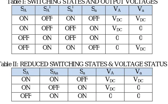
Terminal voltages of the two phase legs can then be any of the four sets of values indicated in Table I.
Table I: SWITCHING STATES AND OUTPUT VOLTAGES
SA SAl Sal Sa VA Va
ON OFF ON OFF VDC VDC
ON OFF OFF ON VDC 0
OFF ON OFF ON 0 0
OFF ON ON OFF 0 VDC
Table II: REDUCED SWITCHING STATES & VOLTAGE STATUS
SA SAa Sa VA Va
ON ON OFF VDC VDC
ON OFF ON VDC 0
OFF ON ON 0 0
Applying the same integration to the remaining two pairs of phase-legs with switches
{SB ,SBl,Sbl,Sb } and {SC ,SCl,Scl,Sc} then results in the integrated energy system shown in Fig. 4. The system in Fig. 3
uses nine switches as compared to twelve for the non-integrated system shown in Fig. 1(b). The same six terminal
voltages are retained with the upper three produced by the dc-ac inverter formed by the upper three switches {SA, SAa,
Sa} and middle three switches {SB, SBb, Sb}. On the other hand, the lower three voltages are produced by three dc-dc
converters formed by the middle three switches {SB ,SBb,Sb} and lower three switches {SC, SCc, Sc}. The middle three
switches are obviously shared by the inverter and converters, which will surely introduce some constraints as already
identified (fourth combination of VA=0V and Va=VDC cannot be produced).
B. Modulation Principles
Fig.4 Integrated Generation system
An example illustrating the three-switch modulation is shown in Fig. 5, where a single carrier band is clearly divided
into h1 and h2. The upper sub-band h1 is assigned to the upper terminal, and hence confines the sinusoidal reference.
Similarly, the lower sub-band h2 is assigned to the lower terminal, and hence encompasses the linear reference.
Comparing the references with the single common carrier based on the following rules then leads to those gating
signals for SA and Sa shown at the bottom of Fig. 5.
Fig.5 Carrier band division and gating signal generation per phase-leg.
V.CONCLUSION
This paper proposes a number of integrated energy systems based on a compact converter topology. The circuit Slightly Complex with reduced switch count, compactness and switching losses are reduced. The switches carries same current. Experimental testing has already confirmed their conceptual validity and practicality, regardless of whether implemented in single- or three-phase form.
REFERENCES
[1] Wei Li; Joos, G.; Belanger, J.; , "Real-Time Simulation of a Wind Turbine Generator Coupled With a Battery Supercapacitor Energy Storage System," Industrial Electronics, IEEE Transactions on , vol.57, no.4, pp.1137-1145, April 2010.
[2]Kalpesh C. Soni, Firdaus Belim, “MicroGrid during Grid connected mode and Islanded mode -A Review”, IJAERD, NCRRET, 2015.
[3] Patil, Roopali; Sarkar, Joydeep; Vinchurkar, Shraddha; ",Implementation of Photovoltaic Energy based Dynamic Voltage Restorer in Grid,"International Journal of Innovative Research in Science, Engineering and Technology (IJIRSET) 2319-8753",4,11,,2015,Ess & Ess Research Publications
[4] C. B. Jacobina, I. S. de Freitas, C. R. da Silva, M. B. de Rossiter Correa, and E. R. C. da Silva, Reduced switch-count six-phase AC motor drive systems without input reactor," IEEE Trans. Ind. Electron., vol. 55, no. 5, pp. 2024-2032, May 2008.