R E S E A R C H
Open Access
Beamforming matrix quantization with variable
feedback rate
Chau Yuen
1*, Sumei Sun
2, Mel Meau Shin Ho
3and Zhaoyang Zhang
4Abstract
We propose a new technique to quantize and feedback the parameters when a beamforming matrix is compressed with the Givens Rotation (GR). We suggest to feedback the parameters with variable feedback rate, and use efficient source coding and codebook to quantize the GR parameters. The variable feedback rate means that the number of bits used to represent the quantized beamforming matrix is based on the value of the matrix itself. And due to the non-uniform distribution of the GR parameters, source coding and code book can be designed to quantize those parameters in a more effective manner. Compared with the fixed feedback rate scheme, the proposed method delivers a better performance without incurring additional feedback bandwidth.
Introduction
Multiple transmit and receive antennas system has been adopted in several communication standards in order to achieve a higher throughput. The open-loop multiple-input multiple-output (MIMO) technique has already been shown to achieve a high performance gain. With the availability of either the full or partial channel state information (CSI) at the transmitter, we can achieve fur-ther performance gain or receiver complexity reduction. Such closed-loop schemes have been considered in many communication standards for application of beamform-ing or multi-user precodbeamform-ing.
However, CSI estimation for the downlink channel at the base station is not possible in Frequency Division Du-plex systems. It is also not straightforward to implement CSI estimation in Time Division Duplex (TDD) systems due to the mismatch in the radio front end. Hence in gen-eral, the CSI will be estimated at the mobile clients and be sent back to the base station. For example, in the 802.11n wireless LAN system, when the system is operated in TDD mode, the channel can either be estimated by the transmitter through calibration or the channel is fed back by the receiver [1]. This unfortunately requires a high and undesirable feedback bandwidth.
Another popular way to reduce the amount of CSI feed-back is through differential encoding [2,3]. However, such
technique suffers accumulated error propagation. There-fore, the mobile client often computes the beamforming matrix, which is usually a unitary matrix and “compress” such a matrix before feeding back to the base station. The “compression”can significantly reduce the feedback band-width requirement. And 802.11 ac wireless LAN system [4] adopts this methodology to feedback the beamforming matrix for single- and multi-user MIMO. Although we only use unitary beamforming matrix as an example in this article, the techniques that are discussed in this article apply to the feedback of channel matrix as well. For ex-ample, we may perform singular value decomposition (SVD) on the channel matrix, and feedback the eigenva-lues and both the left and right eigenvectors matrices, which are both unitary.
There have been several proposals in the literature to compress the beamforming vector. One is codebook based such as the vector quantization (VQ) scheme proposed in [5-10], and another is by using the Givens Rotation (GR) [1,4,11-13]. Compared with the GR-based scheme, the VQ approach requires a higher storage, as a set of codebooks is needed for a particular antenna setting. It has a higher complexity than the GR approach, especially when the number of codewords in the codebook increases. Due to these reasons, the GR approach has been adopted in the 802.11n and 802.11 ac standards [1,4].
In this article, we investigate an effective approach to quantize and feedback the GR parameters that compress the beamforming matrix. The proposed scheme is cap-able of achieving a better performance, in the absence of * Correspondence:Email: [email protected]
1Singapore University of Technology and Design, Singapore, Singapore Full list of author information is available at the end of the article
extra bandwidth, than existing techniques that quantize and feedback the GR parameters.
Signal model MIMO model
Consider a point-to-point MIMO channel with NT
transmit antennas and NR receive antennas, the NT× 1
transmitted signal is denoted byxand theNR×NT
chan-nel denoted by H. The NR× 1 received signal y can be
expressed as
y¼Hxþn ð1Þ
To demonstrate the idea of beamforming, we use the eigen-subspace beamforming as an example. By using SVD, a MIMO channelHcan be decomposed into
H¼UDVH ð2Þ
where U of size NR×R and V of size NT×R are both
unitary matrices, andDis anR×Rdiagonal matrix con-sisting of the singular values of H as its diagonal ele-ments, and R is the rank of H. In order to perform eigen-subspace beamforming,Vneeds to be fed back to the base station. An effort to reduce the amount of in-formation inV was reported in [11-13] where a matrix Σ was multiplied withV to form V, such that the last row of V consists of only real numbers. Hence, we may re-express (2) as:
To transmit data in the firstKeigen modes (whereK≤ R), the beamforming matrixWis simply the firstK col-umn vectors of V:
W¼ Vð1:KÞ ð6Þ
The transmitted signal is related to theK× 1 data sig-naluby
x¼Wu ð7Þ
In order to retrieveu, the mobile client multiplies the received signal withUH,
^u¼UHy¼ D 1:K
ð Þuþne ð8Þ
where ne has the same statistics as n(as U is a unitary matrix). Since D is a diagonal matrix,
eigen-beamforming leads to simple decoding, as the MIMO channel can be treated as a number of parallel subchannels.
In practice, due to the limited bandwidth in the feed-back channel,W has to be quantized, and the base sta-tion receives the quantized version ofW, denoted by We . We assume that the channels are estimated accurately, and there is no error or delay in the feedback channel. With these assumptions we consider only the impact of quantization error due to limited feedback bandwidth. Hence, We , instead ofW, will be used as the beamform-ing matrix. In this article, we propose an effective method to quantizeWand it will be shown that we can achieve a better performance than that of existing meth-ods using the same average number of feedback bits.
GR model
Before we illustrate how the new proposed approach can easily be applied to the GR, we give a brief review on the GR. A unitary matrix, such as W in our case, can be represented as follows:
whereDiis a diagonal matrix andGis defined as
Glið Þ ¼ψli
Hence, the 3 × 2 unitary matrices W can fully be described by just six parameters:ϕ11, ϕ21, ψ21,ψ31, ϕ22, and ψ32. A 3 × 1 unit-norm vector only needs four para-meters, namelyϕ11, ϕ21,ψ21, andψ31. Whereas for 2 × 1 and 2 × 2 cases, two parameters,ϕ11andψ21, will be suf-ficient. The full details can be founded in [1,4].
There are four combinations of bits assigned to the GR parameters in the IEEE 802.11n draft. They can be summarized as follows in the format of (bψ,bϕ), namely
(1,3), (2,4), (3,5), and (4,6), where bψ represents the
number of bits assigned to ψ, and bϕ represents the
from 0 to π/2 whereas ϕ spans over a range from 0 to 2π[1,4].
Using the above bit assignment,ψand ϕcan be quan-tized according to (12) (where ψe and ϕe represent the quantized version ofψandϕ, respectively).
e
The beamforming matrix We can be recovered at the base station by using (14):
e
The three basic ideas of the proposed scheme are as follows:
A.Dynamic bit assignment:
The bits assigned to the GR parameterϕcan be made dependent on the value ofψ. When the resolution is“sparse”(which can be predetermined based on the value ofψ), we use more bits for the quantization ofϕ; when the resolution is“crowded”, we use fewer bits for the quantization ofϕ. In other words, the bit assignment toϕis adaptively adjusted based on the value ofψ.
B.Efficient source coding:
Due to the non-uniform distribution of the GR parametersψ, efficient source coding such as the Huffman code [14] can be used to efficiently encode the GR parameterψand hence reducing the number of feedback bits required.
C.Codebook design:
Due to the same reason of non-uniform distribution, instead of quantizing the GR parameterψin a uniform manner, codebook can be designed so as to quantize the parameter in a more effective manner.
Depending on the receiver structure or the design cri-teria, we can apply each of these ideas separately or jointly. We will illustrate each of the above in more details.
Dynamic bit assignment
To illustrate the idea of dynamic bit assignment, it is best to make use of a simple example of 2 × 1 beam-forming vector. Consider a 2 × 1 unit-norm vector was shown in (15), due to the unit-norm property, it must
satisfy the constraints in (16). In addition, there is a matching between the GRview point and the Geometry view point, i.e., both r1and r2are related toψ21by r1=
Sincewis a unit-norm vector, it must satisfy:
w2
1þw22¼1
⇒r2
1þr22¼1
ð16Þ
Based on the geometry view point in (15) and the con-straints in (16), if we want to reduce the quantization error between the we (quantized w) with w, we obtain the following insights:
Whenr2is large (ψ21is large),r1will be small;ϕ11
can have a lower resolution.
Whenr2is small (ψ21is small),r1will be large;ϕ11
will need a higher resolution.
Hence, the number of bit assigned to ϕ11should be a function of r1 and r2, which is in turn related to the value ofψ21when GR is in use. This observation can be further illustrated in Figures 1 and 2. As shown in Fig-ure 1, the radii of the two circles represent two possible values of r1. This is equivalent to one bit assignment to ψ21. When r2is small, r1will be large, as shown by the blue circle marked with “×” at the bottom of Figure 1. When r2 is large, r1 will be small, noting the red circle marked with “O” at the top of Figure 1. It can be seen that in this case, if we assign the same number of bits (e. g., 3 bits) to ϕ11, it corresponds to eight points on each circle. The points on the upper circle are closer to each other, while the points on the lower circle are further apart. In this case, the total number of bits to represent
wis 1 + 3 = 4 bits. And this is the standard way of quant-izingw, e.g., in the 802.11n standard.
representingwis 1 + 2 = 3 or 1 + 4 = 5, which is 4 bits on average (if the probabilityψ21to be large and small, hence the probability of upper and lower circle are the same).
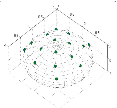
An optimal codebook obtained by VQ methodology as described in [5] is shown in Figure 3. The “optimum” codebook design criterion is to maximize the mean squared inner product (MSIP) of the beamforming vec-tor and the codebook vecvec-tors. A modified form of the generalized Lloyd algorithm was used to train the code-books used in the comparison. During the iterative training process, the nearest neighborhood condition was satisfied by identifying the partition cell Ri
corre-sponding to the ith codebook vector that generates the highest MSIP with the training vector v. At the end of
an iteration, the principal eigenvector of E[vvT|v2Ri]
was computed and became the ith codebook vector. From Figure 3, it can be seen that when using a variable feedback rate the codebook that appears in Figure 2 is closer to the optimal codebook than the one with a fixed feedback rate as shown in Figure 1.
Efficient source coding
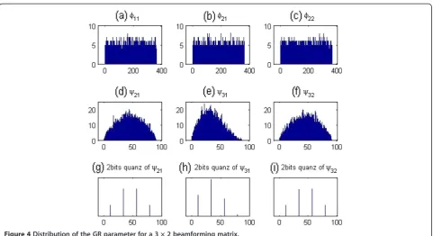
In Figure 4a–f, we show the distribution of the GR para-meters for a unitary beamforming matrix of dimension 3 × 2 when H is Rayleigh i.i.d. fading channel. Through our studies of 5,000 channel matrices, we observe that the par-ameterϕ exhibits a uniform distribution from 0° to 360° (i.e., 0 to 2π), while the parameterψ has a non-uniform distribution from the range of 0° to 90° (i.e., 0 toπ/2). We also observe an asymmetric distribution for ψ31 and a symmetric distribution forψ21andψ32. For channel matri-ces with other dimensions, we have similar observation.
The distributions of the quantized version of ψ when using four levels of granularity are shown in Figure 4g–i. So, we should use less bits to source code those values with higher occurring probability, and more bits to source code those values with lower occurring probabil-ity. One possibility is the use of Huffman source coding [14].
Codebook design
Due to the non-uniform and asymmetric distribution of some of the parameters, instead of quantizing the GR parameters uniformly, we can design a codebook so as to reduce the quantization error. For example, instead of quantizing ψ31 uniformly with 2 bits using the value
Figure 1Distribution of quantized 2-by-1 beamforming vector based on fixed feedback rate.
Figure 2Distribution of quantized 2-by-1 beamforming vector based on variable feedback rate.
[11.25, 33.75, 56.25, 78.75], we can use a codebook [8, 25, 41, 62] that is also 2 bits. As shown in Figure 4, ψ31 has a distribution that concentrate to the left-hand side (i.e., higher chances for smaller value), hence our code-book of [8, 25, 41, 62] also tends to have a lower value than the uniform codebook of [11.25, 33.75, 56.25, 78.75].
The above three techniques can be combined and optimized by certain design criteria, which can be a function of receiver. We will perform two case studies in the following sections, one based on the techniques A and C, and another based on the techniques A and B.
Case studies
Depending on the training symbol placement and the re-ceiver design, we consider two cases. In the first case, a simple receiver is not retrained with the beamforming matrix, hence the receiver does not take the mismatch of the quantized beamforming matrix into account, and it simply uses a parallel decoder. On the other hand, in the second case, the receiver is retrained with the
updated beamforming matrix, hence the mismatch be-tween the quantized beamforming matrix and the chan-nel is taken into account. It uses a more complicated receiver, such as an MMSE receiver.
Receiver with simple parallel decoder
In this section, we consider the receiver as stated in (8), which is repeated below by taking into account the mismatch in the beamforming matrix with the channel
^u¼ D1UHy¼ VWue þ ne ð17Þ
Due to quantization, VWe is no longer an identity matrix, therefore such a simple receiver should be highly sensitive to the quantization error.
In this section, we demonstrate in details how the pro-posed scheme works for a 3 × 1 beamforming vectorw as shown in (18). In Table 1, we show the bit assignment
Figure 4Distribution of the GR parameter for a 3 × 2 beamforming matrix.
Table 1 Number of bits allocation for three transmit antennas beamforming vector
Average feedback bits
Bits allocated
Givens Proposed
bψ31 bψ21 bϕ21 bϕ11 bψ31 bψ21 bϕ21 bϕ11 Remark
8 1 1 3 3 1 1 2, 3, 4 2, 3, 4 Table2
12 2 2 4 4 2 2 3, 4, 5, 6 3, 4, 5, 6 Table3
Table 2 Bit allocation forϕ21andϕ11when the average
number of feedback bit is 8
Bit representative of Bits allocated forϕ21andϕ11 Total
number of feedback bits ψ31
*
ψ21 *
bϕ21 bϕ11
0 0 3 4 9
0 1 4 3 9
1 0 2 3 7
1 1 3 2 7
*
for the GR of the traditional and the proposed schemes. For example, in an average of 8 bits feedback configur-ation, the traditional scheme allocates 1 bit each to ψ21 andψ31, and 3 bits each toϕ11andϕ21. In the proposed
scheme, 1 bit is assigned to ψ21and ψ31, but 2, 3, or 4 bits toϕ11, with the actual assignment (whether 2, 3, or 4 bits) depending on the value ofψ21andψ31, as shown in Table 2. For an average feedback rate of 12 bits, the actual bit assignment is shown in Table 3.
The quantization and reconstruction ofϕare based on the formula in (13). For theψ parameter, sinceψ31 and ψ21 are not uniformly distributed as shown in Figure 4, we design a codebook for those two parameters, the codebook used are shown as the footnote to Tables 2 and 3. Hence, in this case study, we have used the tech-nique “dynamic bit assignment” and “codebook design” that have been mentioned in the previous section.
w¼ r1e jϕ11
r2ejϕ21
r3
2 4
3
5¼ cosψ21cosψ31e jϕ11 sinψ21cosψ31ejϕ21
sinψ31 2
4
3
5 ð18Þ
Since the receiver is not retrained with the beamform-ing matrix, the quantization error will be critical in this case. We first compare the error in quantization by using mean square error (MSE) in (19) or mean angular distance (MAD) [6] in (20).
MSE¼Ejw wej2 ð19Þ
MAD¼E
ffiffiffiffiffiffiffiffiffiffiffiffiffiffiffiffiffiffiffiffiffiffiffiffiffi 1jw wej2 q
ð20Þ
wherein (20) denotes the dot product operation.
Table 3 Bit allocation forϕ21andϕ11when the average
number of feedback bit is 12
Bit representative of Bits allocated forϕ21andϕ11
Total number of feedback bits ψ31* ψ21* bϕ21 bϕ11
00 00 3 6 13
00 01 4 5 13
00 10 5 4 13
00 11 6 3 13
01 00 3 5 12
01 01 4 4 12
01 10 4 4 12
01 11 5 3 12
10 00 3 5 12
10 01 4 4 12
10 10 4 4 12
10 11 5 3 12
11 00 3 4 11
11 01 3 4 11
11 10 4 3 11
11 11 4 3 11
*
Possible values forψ31andψ21are [8 25 41 62] degree.
MSE readings for quantization of 3 × 1 beamforming vector based on the traditional fixed rate feedback ap-proach versus that of the newly proposed scheme based on variable rate feedback are as follows: MSE of 0.11 versus 0.091 (for 8 bits feedback) and MSE of 0.03 ver-sus 0.028 (for 12 bits feedback). MAD readings are as follows: MAD of 0.31 versus 0.282 (for 8 bits feedback) and MAD of 0.162 versus 0.156 (for 12 bits feedback). Hence, the proposed scheme always achieves a lower MSE and MAD than the traditional scheme for both cases of average 8 or 12 bits feedback.
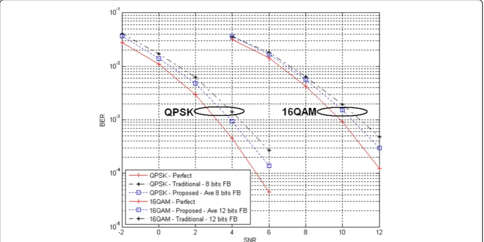
The BER performance is shown in Figure 5 for QPSK (with average 8 bits feedback) and 16QAM (with average 12 bits feedback) modulated 3 × 3 MIMO, respectively. It can be seen that the proposed scheme outperforms the traditional approach. Notably such a performance gain is achieved without any additional feedback bandwidth.
Receiver with MMSE detector
In this section, we consider a different receiver from that in (8). It is assumed that the mismatch in the beamforming matrix is known, and we apply the MMSE detector as shown:
^u ¼GHGþαI1GHy G¼HWe ð21Þ
In this case, we consider a three transmit antennas and two streams of data. Due to the non-uniform
distribution of the parameters ψ as shown in Figure 4, we can make use of Huffman coding [14] to encode the quantized value ofψ. Hence, we make use of the techni-ques“dynamic bit assignment”and “efficient source cod-ing”discussed earlier in this case study.
As shown in Table 4, it is sufficient to represent the quantized version ofψ21(orψ32) andψ31using 1.94 and 1.77 bits (instead of 2 bits for a granularity of four).
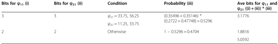
It is also found that when ψ21= 33.75, 56.25, and ψ31= 11.25, 33.75, the quantized version of the beamform-ing matrix will have higher chances of bebeamform-ing poor in qual-ity, hence we suggest that we use 3 bits to quantize ϕ11 andϕ21when the above-mentioned condition occurs. For the rest of the case, we simply use 2 bits to quantizeϕ11 andϕ21. As shown in Table 5, it can be seen that 5.06 bits on average were required for the quantization of ϕ11and ϕ21in our proposed scheme.
Combining everything, the average number of bits required to represent a 3 × 2 unitary beamforming matrix using our proposed scheme can be computed as the following:
Ave bits required : Ebψ21
h i þEbψ31
h i
þEbϕ11þbϕ21
h i
þEbψ32
h i þE bϕ22
h i
¼1:93862þ1:77284þ5:0592þ1:93862þ 2b
¼12:7093
ð22Þ
We compare five different quantization schemes in Table 6. It can be seen that our proposed scheme Table 4 Huffman code for GR parameters
GR parametersψ21andψ32
Quantized value ofψ21orψ32 Probability (i) Huffman code Bits forψ21orψ32(ii) Ave bits forψ21orψ32(i) × (ii)
11.25 0.14714 110 3 0.44142
33.75 0.35496 0 1 0.35496
56.25 0.35146 10 2 0.70292
78.75 0.14644 111 3 0.43932
1.93862
GR parametersψ31
Quantized value ofψ31 Probability (i) Huffman code Bits forψ31(ii) Ave bits forψ31(i) × (ii)
11.25 0.2722 10 2 0.5444
33.75 0.47748 0 1 0.47748
56.25 0.2299 110 3 0.6897
78.75 0.02042 111 3 0.06126
1.77284
Table 5 Bits assignment for GR parametersϕ11andϕ21
Bits forϕ11(i) Bits forϕ21(ii) Condition Probability (iii) Ave bits forϕ11and ϕ21((i) + (ii)) * (iii)
3 3 ψ21= 33.75, 56.25 (0.35496 + 0.35146) *
(0.2722 + 0.47748) = 0.5296
3.1776 ψ31= 11.25, 33.75
2 2 Otherwise 1–0.5296 = 0.4704 1.8816
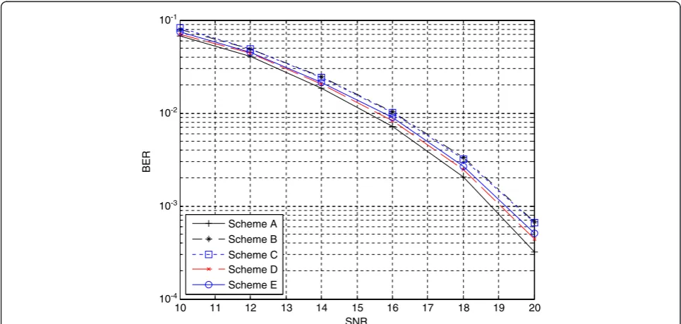
(Scheme E with average 12.71 bits of feedback) achieve similar performance as Scheme D that requires 15 bits of feedback. Hence, we save about 2 bits of feedback, and this saving can be significant when there is a large number of subcarriers, especially in the future broad-band system. Compare to Schemes B and C, we achieve a better performance with 0.71 additional bits in the average number of feedback bit.
The simulation results of the BER for the five schemes are shown in Figure 6. We assume three transmit anten-nas and three receive antenanten-nas with eigen beamforming and two data streams: one 64QAM and the other 16QAM, hence a 10 bits/s/Hz spectral efficiency is achieved. It can be seen that Schemes B and C gave the worst BER, while Scheme A delivered the best perform-ance in terms of BER. Scheme D performed better than Schemes B and C by using three more average feedback bits. Our proposed scheme can capture most of the gain that can be provided by Scheme D, but we require only 0.71 additional feedback bits compared to the additional 3 bits required by Scheme D.
The newly proposed scheme can be considered as a hybrid of the traditional GR approach and VQ-based ap-proach, i.e., we have a code book for the GR parameters ϕ and ψ. However, the new scheme has a lower storage requirement than those based on VQ codebooks.
The assignment of the number of bits and the code-book design in these case studies are just for illustration, there could be other assignment methods that lead to better performance, and different receiver or different system design may lead to different design criteria.
Conclusions
In this article, a simple quantization scheme has been presented for the unit-norm beamforming vector or uni-tary beamforming matrix based on variable-rate feed-back. The basic idea is to provide for higher resolution in the dense area and lower resolution in the sparse area. The idea can directly be applied to the existing GR ap-proach allocating variable bits to the ϕ parameter according to the value ofψ. Due to the non-uniform dis-tribution of the GR parameter ψ, the performance can be further improved if we incorporate into the system efficient source coding and codebook design for GR parameters. Results show that the proposed scheme can achieve a lower MSE and lower MAD. The BER per-formance of the close-loop MIMO system based on the proposed quantization scheme also outperforms that of existing schemes.
The proposed idea is not restricted to the use of eigen-beamformer or GR which have been used as the Table 6 Five schemes for comparisons
Bit assignment Ave number of feedback bits
Scheme A Perfect feedback ∞
Scheme B bψ= 1 andbϕ= 3 12
Scheme C bψ= 2 andbϕ= 2 12
Scheme D bψ= 2 andbϕ= 3 15
Scheme E (proposed) Tables4and5 12.71
10 11 12 13 14 15 16 17 18 19 20
10-4
10-3
10-2
10-1
SNR
BER
Scheme A Scheme B Scheme C Scheme D Scheme E
baseline for comparison. Our proposed method gives a better accuracy when compressing a unit-norm vector or unitary matrix, and such accuracy plays an important role in many communications system including precod-ing for multi-user MIMO.
Competing interests
The authors declare that they have no competing interests.
Acknowledgment
This study was partly supported by the Singapore University Technology and Design (grant no. SUTD-ZJU/RES/02/2011). Zhaoyang Zhang’s was supported in part by the National Key Basic Research Program of China (No.
2012CB316104) and Zhejiang Provincial Natural Science Foundation of China (No. LR12F01002).
Author details 1
Singapore University of Technology and Design, Singapore, Singapore. 2Institute for Infocomm Research, Singapore, Singapore.3Cortex I.T. Labs, Melbourne, VIC, Australia.4Zhejiang University, Hangzhou, China.
Received: 3 December 2011 Accepted: 5 June 2012 Published: 21 June 2012
References
1. IEEE P802.11n/D2.0, IEEE Standards Draft, February 2007
2. W.H. Chin, C. Yuen,Design of differential quantization for low bitrate channel state information feedback in MIMO-OFDM systems(Proc. IEEE VTC 2008 Spring, Singapore, 2008), pp. 827–831
3. M. Cho, W. Seo, Y. Kim, D. Hong,A joint feedback reduction scheme using delta modulation for dynamic channel allocation in OFDMA systems(Proc. of PIMRC, Berlin, 2005), pp. 2747–2750. vol. 4
4. IEEE P802.11ac/D0.2, IEEE Standards Draft, March 2011
5. J.C. Roh, B.D. Rao,Channel feedback quantization methods for MISO and MIMO systems, vol. 2(IEEE PIMRC, Spain, 2004), pp. 805–809
6. D.J. Love, R.W. Heath, T. Strohmer, Grassmannian beamforming for multiple-input multiple-output wireless system. IEEE Trans. Inf. Theory49, 2735–2747 (2003) 7. K.A. Chun, D.J. Love, On the performance of random vector quantization
limited feedback beamforming in a MISO system. IEEE Trans. Wirel. Commun.6, 458–462 (2007)
8. V. Raghavan, R.W. Heath, A.M. Sayeed, Systematic codebook designs for quantized beamforming in correlated MIMO channels. IEEE J. Sel. Ares Commun25, 1298–1310 (2007)
9. S. Yang, J. Ko, Y. Lee,Transmit beamforming with reduced feedback information in OFDM based wireless systems(VTC Spring, Singapore, 2008), pp. 983–987
10. P. Wu, L. Li, P. Zhang, Unitary space vector quantization codebook design for precoding MIMO system. IEICE Trans. Commun.91, 2917–2924 (2008) 11. J. Kim, C. Aldana,Efficient feedback of the channel information for closeloop
beamforming in WLAN(IEEE VTC-Spring, Melbourne, 2006), pp. 2226–2230 12. J.C. Roh, B.D. Rao, Efficient feedback methods for MIMO channels based on
parameterization. IEEE Trans. Wirel. Commun.6(1), 282–292 (2007) 13. M.A. Sadrabadi, A.K. Khandani, F. Lahouti, Channel feedback quantization for
high data rate MIMO systems. IEEE Trans. Wirel. Commun.5, 3335–3338 (2006) 14. T.M. Cover, J.A. Thomas,Elements of Information Theory(Wiley Interscience,
1991)
doi:10.1186/1687-1499-2012-200
Cite this article as:Yuenet al.:Beamforming matrix quantization with
variable feedback rate.EURASIP Journal on Wireless Communications and
Networking20122012:200.
Submit your manuscript to a
journal and benefi t from:
7Convenient online submission
7Rigorous peer review
7Immediate publication on acceptance
7Open access: articles freely available online
7High visibility within the fi eld
7Retaining the copyright to your article