R E S E A R C H
Open Access
Research on micro-feature extraction algorithm of
target based on terahertz radar
Zhengwu Xu
*, Jian Tu, Jin Li and Yiming Pi
Abstract
Micro-Doppler motion of a target is an important characteristic in high-resolution radar observation. The target feature extraction of micro motion has already been applied to many aspects of radar research. In this article, general model is established for the echo signal of a target with micro-motion. Combination of time-frequency analysis method, a method using Radon transformation to detect the parameters of lines and sinusoidal curves to estimate motion parameters of target is proposed, and the estimation of reflection coefficients of scatterers is completed through nonlinear least squares and CLEAN algorithm. The simulation result shows that this method of Radon transformation has the advantages of high precision and strong anti-noise and can extract the parameters well. The model of echo signal and method of parameter estimation are useful for radar target detection and identification.
Keywords:Micro-Doppler, Time-frequency analysis, Feature extraction, Radon transformation, NLS algorithm
1. Introduction
Mechanical vibration or rotation of structures in a target may induce frequency modulation on returned signals and generate sidebands about the center frequency of the target’s Doppler frequency [1]. The modulation due to vibrations and rotations is called micro-Doppler phenomenon. Micro-Doppler phenomenon is very common in nature, such as the human heartbeat, vibration, or spin of missile warheads, etc.. . .while in terahertz band micro-Doppler phenomenon is particularly significant. The micro-Doppler effect enables us to determine the dynamic properties of the target and it offers a new approach for the analysis of target signatures. Micro-Doppler features serve as additional target features that are complementary to those made available by existing methods. The micro-Doppler effect can be used to identify specific types of vehicles, and determine their movement and the speed of their engines.
In this article, considering the micro-motion of target in the terahertz band, the echo model is established [2], time-frequency transformation and Radon transformation are applied to extract the micro characteristic parameters [3-6], Radon transformation is generally used to detect straight,
based on Radon transformation, we propose a method using Radon transformation to detect the parameters of lines and sinusoidal curves to estimate the motion parame-ters of target. And the estimation of reflection coefficient of scatterers is completed through nonlinear least squares (NLS) and the CLEAN algorithm [2,7]. These are very helpful for radar target detection and identification [8].
2. Target echo modeling
We assume a target of multiple scatterers containing macro- and micro-motion to do a compound movement on the radar radial direction. In general, targets always do non-uniform linear motion in radical direction, which can be deemed as high-order motion, the formula. Its movement rule is a higher order polynomial of timetor the infinite series oft. Weierstrass quantitative shows that arbitrary radial rule of motion may be a finite polynomial oftapproximation
R1ð Þ≈t X
n
j¼0
ajtj ð1Þ
where n is the number of finite polynomial, micro objectives of the target can be approximated as vibration or rotation movement, its rule of motion is
R2ð Þ ¼t AsinðBtþφÞ ð2Þ
* Correspondence:[email protected]
School of Electronic Engineering, University of Electronic Science and Technology of China, Chengdu 611731, China
where Ais the vibration amplitude,Bis the frequency of vibration, φ is the initial rotation angle, when t = t, the distance between target and the radar is
R tð Þ ¼R0þX
n
j¼0
ajtjþAsinðBtþφÞ ð3Þ
Then the echo of target can be expressed as
S tð Þ ¼X
whereσiis the scattering coefficient of theith scatterer,f0
is the radar carrier frequency,cdenotes the speed of light. Here, we only consider the condition ofj= 1 andj= 2.
Whenj= 2, and the body of target is doing a uniformly accelerated motion, that is Xn
j¼0ajtj¼v0tþat2, then
the rule of target’s motion can be approximated as
R tð Þ ¼R0þv0tþat2þAsinðBtþφÞ ð5Þ
and the phase of the baseband signal is
Φð Þ ¼t 4λπ R tð Þ ¼4λπ R0þv0tþat2þAsinðBtþφÞ
ð6Þ
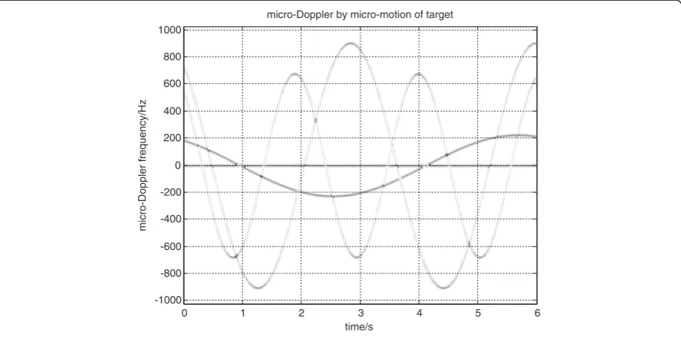
where λ denotes radar wavelength, according to the definition of micro-Doppler, the micro-Doppler frequency of target equal to the derivative of phase with respect to time, then the instantaneous frequency of the signal can be expressed as By using time-frequency transformation with respect to the echo of target, one can get its micro-Doppler frequency. Figure 1 is obtained in the simulation conditions as follows: radar carrier frequencyf0= 340 GHz, sampling frequency fs = 4096 Hz, sampling points N = 512, and observation
timet= 6 s. Assume that there are four scatterers, and
v0= 0.03 m/s2, a= 0.01 m/s2,σ1= 1,σ2= 0.9, σ3= 1,
σ4= 1,A1=B1=φ1= 0,A2=A4= 0.1,A4= 0.2,B2= 3
rad/s,B3= 2 rad/s,B4= 1 rad/s,φ2=φ3=φ4= 0.6 rad.
3. Parameter estimation
3.1. Micro-feature extraction based on Radon transformation
Previously, we established the echo model of target with micro-motion, and time-frequency transformation of the echoed signal is applied to gain the time-varying micro-Doppler frequency features of target. This section is to estimate the motion parameters of target with micro-motion, namely to extract the curves of target’s
motion from the time-varying micro-Doppler fre-quency image.
We assume that the set of parameters to be estimated is
θ=v0,a,A,B,φ, as the straight line in Figure 1 is only
related to parameters (v0, a), we can divide it into a
two-dimensional matrix and three-dimensional matrix to estimate, respectively, which can greatly reduce the calculation. First we will estimate (v0, a) as shown in
Figure 1.
Straight line detection can be realized by Radon transformation. A projection of a two-dimensional function
f(x,y) is a linear integral in a certain direction. In general, the Radon transformation off(x,y) is defined as the linear integral offalong a line. In two-dimensional space, Radon transformation can be defined by Equation (8)
Rðρ;θÞ ¼∬ distance between the origin of coordinates and the line, θ is the angle between the line and x-axis, δ is a unit pulse function.
Radon transformation can be seen as the projection of the image in the ρ – θ space, of which each point corresponds to a straight line in the image space. And Radon transformation is the integral of the image pixels on each straight line, then each straight line in the image will become a bright spot in theρ–θ space, which turn the line detection into detecting highlights in Radon domain.
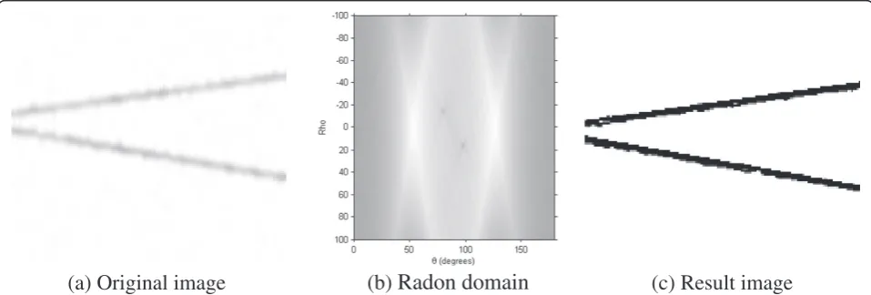
As can be seen from Figure 2a, there are two straight lines to be detected, the result of Radon transformation can be showed at Figure 2b. On Radon domain, there are peaks which indicate that there are lines on image domain.
From Figure 2b, it is easy to determine peaks’position, which is interpreted by ρ and θ. After detecting the value of ρ and θ, we can detect the straight lines on image domain. The result is showed in Figure 2c.
As seen in the result, Radon transformation can detect a straight line very accurately in the case of low SNR. And we can detect the parameters of the line in Figure 1 that the linear parameters estimated arem= 45.5,c= 68.2 (mis the slope,c is the intercept), respectively. Taking
m = 4a/λ and c = 2v0/λ into consideration we have ⌢
S0ð Þ ¼t S tð Þ exp j4πf0
c ⌢ v0tþat⌢ 2
≈Xk
i¼1
σiexp j
4πf0
c ðR0þAisinðBitþφiÞÞ
ð9Þ
Now time-frequency transformation of the echo signal is carried out in the same simulation condition as Figure 1, as shown in Figure 3.
There are a few methods for micro-Doppler feature extraction such as W–Vpeak detection method [9] and the normalized first moment method [10] that are all based on time-frequency analysis methods. Here, Radon transformation detection method is chosen.
The basic idea of Radon transformation detecting curve is to do a linear integral along a specific path in a plane.
According to Equation (7), the target micro-Doppler frequency is fd¼2λ ABcosðBtþφÞ after compensating the phase, and the amplitude of the sinusoidal curve in Figure 3 is2AB
λ , the vibration frequency isB. Now we let
p tð Þ ¼2λ x y cosðytþzÞ ð10Þ
Then the amplitude, frequency, initial phase of the sinusoidal curve in Figure 3 is determined by the three space coordinatesx,y,z, respectively.
(a) Original image
(b)
Radon domain
(c) Result image
Figure 2Line detection using Radon transformation. (a)Original image.(b)Radon domain.(c)Result image.
time/s
micro-Doppler frequency/Hz
micro-Doppler by micro-motion of target
0 1 2 3 4 5 6
-1000 -800 -600 -400 -200 0 200 400 600 800 1000
The steps to parameterize the sinusoidal curves are given as follows:
1. Set the range ofx,y,z, and establish a discrete parameter space.
2. Establish a three-dimensional accumulator array P(X,Y,Z), and initialize all elements ofP(X,Y,Z) to zero.
3. Calculate the value ofpfor each point in the parameter spacex,y,zaccording to Equation (10) att.
4. Take over all values of t to calculate the linear integralXtg t;ð pÞof the time-varying micro-Doppler frequency image along the curvep(t).
5. Find the local peak of the accumulator to obtain the spatial coordinate position of (X,Y,Z).
After Radon transformation, each curve in the time-varying micro-Doppler frequency image will generate a corresponding peak in the parameter domain, the parame-ters of each scatterer can be estimated by detecting the position of peaks in the parameter domain.
Figure 4a,b shows the parameter domain image after transforming when there is no noise, and Figures 4c,d the parameter domain image with noise.
As seen from Figure 4, in the image domain, the scatterers’ echo curve entangled with each other, but in the parameter domain, there are four distinct peaks corresponded to the curves. There may be a certain deviation between the true value and the parameter value extracted from the parameter domain after Radon transformation, in order to improve the accuracy
of the estimated parameter, we let the estimated value to be the initial value, and search again with a small step in its nearby space, then the accurate estimated value of the parameter can be obtained.
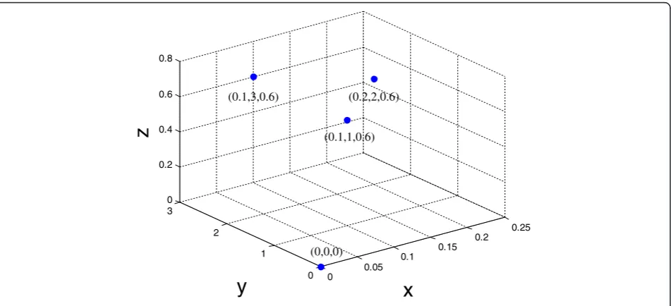
Simulation results show that the estimated values of the parameters are the same whether there is noise or no noise, and the space coordinates of the parameters are shown in Figure 5.
The coordinates of the parameters corresponded to the four scatterers are (0,0,0), (0.1,3,0.6), (0.2,2,0.6), (0.1,1,0.6), thenA1=x1= 0,A2=x2= 0.1, A3=x3= 0.2, A4 = x4 = 0.1, B1 = y1 = 0, B2 = y2 = 3, B3 = y3 = 2, B4=y4= 0,C1=z1= 0,C2=C3=C4= 0.6. And (0, 0, 0)
represents the sinusoidal line with amplitude, frequency, and initial phase are zero, which is equivalent to a straight line.
As can be seen from the above results, the Radon transformation detection method has the advantages of high precision and strong anti-noise. Its detection accuracy is determined by the size of the space grid of the three-dimensional accumulator, if the grid is small, the accuracy will be high, but the computational complexity of the algorithm grows rapidly as well.
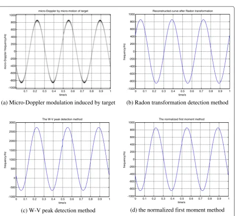
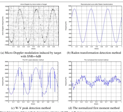
The simulation comparison result ofW–Vpeak detection method and the normalized first moment method are shown in Figure 6.
From the figure, we can know that in the condition of single scatterer without noise, the three methods can all extract micro-Doppler information very accurately.
As can be seen from Figure7, while adding noise, both the W–V peak detection method and the normalized
time/s
micro-Doppler frequency/Hz
micro-Doppler by micro-motion of target
0 1 2 3 4 5 6
-1000 -800 -600 -400 -200 0 200 400 600 800 1000
first moment method have been unable to accurately estimate the parameters of target micro-Doppler.
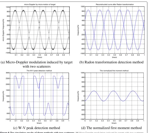
As seen from Figure 8, In the condition of multiple scatterers, the normalized first moment method has been completely ineffective, and the envelope ofW–Vpeak
detection method is close to the target micro-Doppler frequency, but still cannot make accurate estimates. While the Radon transformation detection method proposed in the article can maintain high accuracy even in the condition of multiple scatterers with strong noise.
(a)
The parameter domain normalized image without noise(b)
The parameter domain image without noise(c)
The parameter domain normalized image with noise(d)
The parameter domain image with noiseFigure 4The parameter domain normalized image after Radon transformation. (a)The parameter domain normalized image without noise.
(b)The parameter domain image without noise.(c)The parameter domain normalized image with noise.(d)The parameter domain image with noise.
0 0.05 0.1
0.15 0.2 0.25
0 1 2 3 0 0.2 0.4 0.6 0.8
x
y
z
(0.1,3,0.6) (0.2,2,0.6)
(0.1,1,0.6)
(0,0,0)
3.2. Scattering coefficient estimating based on NLS
In cases when the parameters of scatterers have been estimated, the NLS algorithm may be applied to the data with previously estimated scattering coefficient responses removed via the CLEAN algorithm. The echo of target is
S tð Þ ¼X
then theith iteration of NLS may be expressed as
min⌢
(i − 1)th scatterer estimated and removed. For i = 1,
S0(t) = S(t) and Si(t;θ) denote the radar echo of ith
scatterer. To solve Equation (12), set the derivative of
Ið Þσ⌢ with respect to the parameter⌢σ to zero, i.e., estimation of the reflection coefficient of that scatterer can be given by
time/s
micro-Doppler frequency/Hz
micro-Doppler by micro-motion of target
0.1 0.2 0.3 0.4 0.5 0.6 0.7 0.8 0.9 1
(a) Micro-Doppler modulation induced by target
0 0.1 0.2 0.3 0.4 0.5 0.6 0.7 0.8 0.9 1
Reconstructed curve after Radon transformation
(b) Radon transformation detection method
0 0.1 0.2 0.3 0.4 0.5 0.6 0.7 0.8 0.9 1
The W-V peak detection method
(c) W-V peak detection method
0 0.1 0.2 0.3 0.4 0.5 0.6 0.7 0.8 0.9 1
The normalized first moment method
(d) the normalized first moment method
⌢
Following the CLEAN approach, after estimating each scatterer’s reflection coefficient, the current scatterer is subtracted from the frame via (13), and (12) is re-initialized with the location of the next strongest peak. This procedure is performed until the reflection coefficient of all the scatterers has been estimated. In this simulation, the estimated reflection coefficients of the four scatterers are⌢σ1¼1:0180;σ⌢2¼0:8822;σ⌢3¼1:0174; ⌢
σ4¼1:0070 . In order to measure the accuracy of this
algorithm, we define maximum relative error and mean
square error of estimated scattering coefficient as Equations (16) and (17).
whereNrepresents the number of scatterers, here,N= 4, σrepresents the real reflection coefficient of the scatterers,
⌢
σ denotes the estimated value.
From Equations (16) and (17), it can be calculated that the maximum relative error is 1.98%, and the mean quare error is 2.48 × 10⁻⁴, this shows that the
time/s
micro-Doppler frequency/Hz
micro-Doppler by micro-motion of target
0.1 0.2 0.3 0.4 0.5 0.6 0.7 0.8 0.9 1
(a) Micro-Doppler modulation induced by target
with SNR=-6dB
Reconstructed curve after Radon transformation
(b) Radon transformation detection method
0 0.1 0.2 0.3 0.4 0.5 0.6 0.7 0.8 0.9 1
The W-V peak detection method
(c) W-V peak detection method
0 0.1 0.2 0.3 0.4 0.5 0.6 0.7 0.8 0.9 1
The normalized first moment method
(d) The normalized first moment method
algorithm can be used to extract the parameters of scattering coefficient well.
Establish the detection model of target after extracting all the parameters
all the parameters in the equation are given in Table 1. If j in Equation (4) isj = 1, use the above method to estimate the parameters and establish the detection model of target.
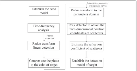
The flow chart of this algorithm is shown in Figure 9.
4. Conclusion
This article establishes a novel echo model of target with micro-motion to analyze the characteristics of micro motion and investigates methods for motion parameter estimation and micro-Doppler signature extraction from target. Estimation of micro-motion parameters is completed through time-frequency transformation of
time/s
micro-Doppler frequency/Hz
micro-Doppler by micro-motion of target
0.1 0.2 0.3 0.4 0.5 0.6 0.7 0.8 0.9 1
(a) Micro-Doppler modulation induced by target
with two scatterers
0 0.1 0.2 0.3 0.4 0.5 0.6 0.7 0.8 0.9 1
Reconstructed curve after Radon transformation
(b) Radon transformation detection method
0 0.1 0.2 0.3 0.4 0.5 0.6 0.7 0.8 0.9 1
The W-V peak detection method
(c) W-V peak detection method
0 0.1 0.2 0.3 0.4 0.5 0.6 0.7 0.8 0.9 1
The normalized first moment method
(d) The normalized first moment method
Figure 8The simulation results of three methods with two scatterers. (a)Micro-Doppler modulation induced by target with two scatterers.
(b)Radon transformation detection method.(c)W–Vpeak detection method.(d)The normalized first moment method.
Table 1 The estimated parameters of all scatterers ⌢
v0 ⌢a
⌢
A B⌢ ⌢ ϕ ⌢σ
Scatterer 1 0.03 0.010 0 0 0 1.0180
Scatterer 2 0.03 0.010 0.1 3 0.6 0.8822
Scatterer 3 0.03 0.010 0.2 2 0.6 1.0174
the echoed signal and Radon transformation in terahertz band, and NLS and the CLEAN algorithm are utilized to estimate the scattering coefficients of each scatterer. This simulation result proves that Radon transformation detection method has high precision and good anti-noise performance which can accurately extract the micro-parameters. By adopting this estimate method, exact parameters are obtained for given signals. Thus, greatly precise the steps of target detection and identification.
Competing interests
The authors declare that they have no competing interests.
Acknowledgement
This study was supported by the National Natural Science Foundation of China under Projects 61271287 and the Fundamental Research Funds for the Central Universities under Projects ZYGX2012J029.
Received: 4 December 2012 Accepted: 3 February 2013 Published: 19 March 2013
References
1. VC Chen, FY Li, SS Ho, Micro-Doppler effect in Radar phenomenon, model and simulation study. IEEE Trans AES42(1), 2–21 (2006)
2. OR Fogle, Micro-range-micro-Doppler feature extraction and association, in IEEE Radar Conference(, Kansas City, MO, 2011), pp. 167–171. 2011 3. J Li, Y Pi, Research on terahertz radar target detection algorithm based on
the extraction of micro motion feature. J Electron Meas Instrum24(9), 803–807 (2010)
4. VC Chen, H Ling,Time-Frequency Transform for Radar Imaging and Signal
Analysis(Artech House, Boston, 2002)
5. B Boashash,Time-Frequency Signal Analysis and Processing(Elsevier Ltd., Amsterdam, 2003)
6. MI Sari, Detection and reconstruction of geometric object based on line detection using radon transform, inInternational Conference on Electrical Engineering and Informatics (ICEEI) 2011, 17–19 July 2011(Bandung, 2011), pp. 1–6
7. Q Wang, M Xing, High-resolution three-dimensional radar imaging for rapidly spinning targets, geoscience and remote sensing. IEEE Trans Geosci Remote Sens1, 22–30 (2008)
8. JJ Lei, C Lu, Target classification based on micro-Doppler signature, in
Proceedings of International Conference on Radar(Washington, USA, 2005),
p. 179183. 2005
9. C Hongyong, L Yongxiang, Analysis of micro-Doppler and parameters estimation. J Infrared Millim Waves25(5), 360–363 (2006)
10. S Hui-xia, L Zheng, Micro-doppler feature extraction for ballistic missile warhead, inInformation and Automation, 2008(Changsha, 2008), pp. 1333–1336
doi:10.1186/1687-1499-2013-77
Cite this article as:Xuet al.:Research on micro-feature extraction algorithm of target based on terahertz radar.EURASIP Journal on Wireless Communications and Networking20132013:77.
Submit your manuscript to a
journal and benefi t from:
7Convenient online submission
7Rigorous peer review
7Immediate publication on acceptance
7Open access: articles freely available online
7High visibility within the fi eld
7Retaining the copyright to your article
Submit your next manuscript at 7 springeropen.com