© 2015, IRJET.NET- All Rights Reserved
Page 938
Power Losses Estimation in Distribution Network (IEEE-69bus) with
Distributed Generation Using Second Order Power Flow Sensitivity
Method
Meghana.T.V
1, Swetha.G
2, R.Prakash
31
Student, Electrical and Electronics, Acharya Institute of Technology, Karnataka, India
1 2Assistant Professor, Electrical and Electronics, Acharya Institute of Technology, Karnataka, India
23
Professor, Electrical and Electronics, Acharya Institute of Technology, Karnataka, India
3---***---Abstract –
The demand for electricity is increasing day by day and the generation of power is not meeting the demand and also the losses experienced in transmission and distribution are the main causes of load shedding in India. We can reduce or counteract the losses by generating more power in conventional generating stations which needs huge investment, or byincorporating Distributed generators in the
Distribution Network with very less investment which
generates power of few Mega Watts . Distribution
network which is the last stage of delivery of electricity to consumers experiences losses which can be minimized by local Distributed generators (DG). Distributed Generation also called as decentralized generation, on site generation are incorporated in the
Distribution Network to eliminate the
interdependencies on the utility and also for the continuous supply of power which boosts the efficiency in the delivery of power to the consumers. The Distributed Generators incorporated are time varying where repetitive power flow simulations are done to calculate the power losses which is time consuming
and makes the calculation complex. Optimal
placement of DG plays a significant role in minimizing power losses in Distribution systems. In this paper the total power losses of the distribution network (IEEE-69 bus) for any new DG condition is estimated by a single power flow method called Second order power flow sensitivities which helps in modeling the non linear nature of power losses. Therefore this method speeds up the solution of power losses reduction, DG allocation problems where several DG configurations are taken into consideration.
Key
Words:
Distributed
Generation
(DG),
Decentralized
generation,
on
site
generation,
Distribution Network (DN), second order power flow
sensitivities, non linear losses
1.
Introduction
The first order sensitivity method such as Newton Raphson when used yields results only for operating conditions around base case DG. The error between the first order sensitivities and the power losses grow exponentially for large excursions of DG power output this is due to quadratic behavior of losses whose first order sensitivities may change significantly for large DG variation. To solve this issue this paper presents the method to estimate the total power losses of DNs for any DG condition.
© 2015, IRJET.NET- All Rights Reserved
Page 939
………(2)
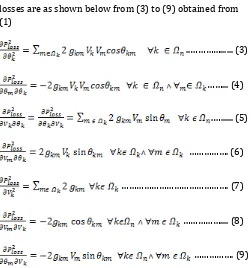
θkm is the difference between phase angles of buses k and m Vk and Vm are the nodal voltage of bus k and bus m respectively gkm and bkm are the conductance and the susceptance of the line k-m respectively. The second order partial derivatives of the real power losses are as shown below from (3) to (9) obtained from (1) ..…………... (3)
……... (4)
.…... (5)
………. (6)
………. (7)
……….... (8)
………. (9)
Where is the set of buses connected to bus k and is the total number of buses of the distribution network The reactive power losses are also derived in the same manner as shown for the active power losses The second order active power loss sensitivities for a system with n buses can be calculated from (10) to (13) they are called as Hessian matrix.
1.1 Hessian Matrix 1
It is a square matrix which contains second order partial derivatives as shown above. We are using the Hessian matrix in the calculation of active and reactive loss sensitivities. ………(10)© 2015, IRJET.NET- All Rights Reserved
Page 940
……… (12)
………... (13)
The order of all the matrices is n-1 * n-1 which means there is one power loss sensitivity for each bus of the system except for the substation bus, where voltage
magnitude and phase angle are assumed to be fixed. The
reactive power loss sensitivities ( , ) are
similar to (10) to (13) with replaced by . The
elements of these four sensitivity matrices are obtained by differentiating (2) twice with respect to voltage magnitude (V) and phase angle (θ) .
The second order sensitivity power flow is applied to IEEE-69 bus Distribution network and the power losses are estimated in the same.
© 2015, IRJET.NET- All Rights Reserved
Page 941
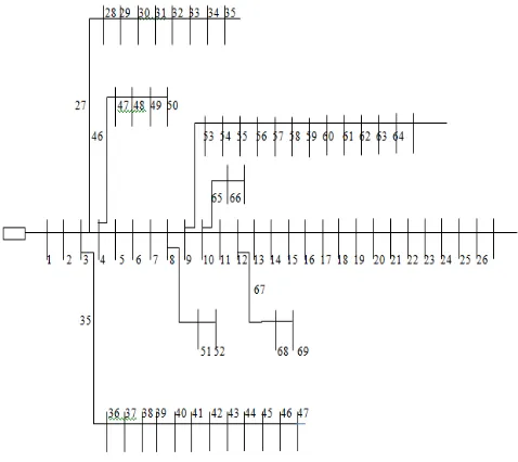
Fig 2: IEEE 69 bus Distribution Network
3. RESULTS
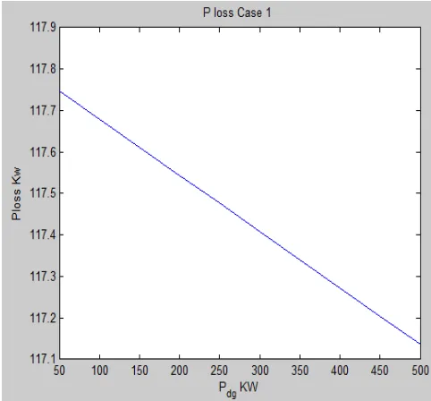
3.1 Location of DG 1
The active and reactive power losses when the DG is placed at different buses are as shown in figure (1) and (2) respectively. The graph tells us clearly the power losses totally depend on the DG placement. When the DG is placed at bus 62 it supplies the demand of downstream buses 63-66 which in turn reduces the power flow passing through the buses upstream of bus 63 (e.g., buses 1-9). As a result total power losses are decreases.
Fig 3: Total active power losses under maximum demand
of 500kW.
Fig 4: Total reactive power losses under maximum
© 2015, IRJET.NET- All Rights Reserved
Page 942
Fig 5: Comparision of first order and second order
sensitivities method.
Table-1: Comparision of real power losses in IEEE-69 bus
test system without placement of DG.
Sl.no First order
Table-2: Comparison of real power losses in IEEE-69 bus
test system with placement of DG at 62nd bus.
Sl.no Rating buses with fixed and varied generation is explained in this section. The Distribution network as shown in figure (2) is supplied by two DG units. One DG is placed at 18th bus
with fixed generation of 500kW and another DG is placed at 66th bus with varied generation from 0 to 500kW
through steps of 50kW.
We can observe that as DG unit placed at 66th bus is varied
in steps i.e., as the generation level is increased the impact of DG66 is increased. When both the DG’s are operating at
500kW we find out that it is advantageous to install a DG
unit at 66th bus than at 18th bus.
The real and reactive power losses with the placement of DG are as shown in figure (6) and (7) .
Fig 6: Real power losses when DG is placed at 18th bus
with fixed generation of 500kW and variable generation in steps of 50kW at 66th bus
Fig 7: Reactive power losses when DG is placed at 18th bus
© 2015, IRJET.NET- All Rights Reserved
Page 943
4. CONCLUSIONS
The second order method is effectively tested on IEEE-69 bus distribution network and gives the exact active and “Distribution feeder reconfiguration for loss reduction,” IEEE Trans. Power Del., vol. 3, pp. 1217–1223, Jul. 1988. [2] E.M. Carreno, R. Romero, and A. Padilha-Feltrin, “An efficient codification to solve distribution network reconfiguration for loss reduction
problem,” IEEE Trans. Power Syst., vol. 23, no. 4, pp. 1542– 1551, Nov. 2008.
[3] M. E. Baran and F. F.Wu, “Optimal capacitor placement on radial distribution systems,” IEEE Trans. Power Del., vol. 4, no. 1, pp. 725–734, Jan. 1989.
[4] G. Levitin, A. Kalyuzhny, A. Shenkman, and M. Chertkov, “Optimal capacitor allocation in distribution systems using a genetic algorithm
and a fast energy loss computation technique,” IEEE Trans. Power Del., vol. 15, no. 2, pp. 623–628, Apr. 2000.
[5] V. H. M. Quezada, J. R. Abbad, and T. G. S. Roman, “Assessment of energy distribution losses for increasing penetration of distributed
generation,” IEEE Trans. Power Syst., vol. 21, no. 2, pp. 533–540,May 2006.
[6] L. F. Ochoa and G. P. Harrison, “Minimizing energy losses: Optimal accommodation and smart operation of
renewable distributed generation,” IEEE Trans. Power
Syst., vol. 26, no. 1, pp. 198–205, Feb. 2011.
[7] E. Carpaneto, G. Chicco, and J. S. Akilimali, “Branch current decomposition method for loss allocation in radial distribution systems with
distributed generation,” IEEE Trans. Power Syst., vol. 21, no. 3, pp. 1170–1179, Aug. 2006.
[8] P.M. Costa andM. A.Matos, “Loss allocation in
distribution networks with embedded generation,” IEEE
Trans. Power Syst., vol. 19, no. 1, pp. 384–389, Feb. 2004.
[9] S.-J. Lee, “Calculation of optimal generation for system loss minimization using loss sensitivities derived by angle reference transposition,”
IEEE Trans. Power Syst., vol. 18, no. 3, pp. 1216–1217, Aug. 2003.
[10] H.M. Ayres, L. C. P. da Silva,W. Freitas, M. C. de Almeida, and V. F. da Costa, “Evaluation of the impact of distributed generation on power losses by using a
sensitivity-based method,” in Proc. 2009 IEEE PES General Meeting, pp. 1–6.