doi:10.1155/2010/763614
Research Article
Cross-Layer Design of the Inter-RAT Handover between
UMTS and WiMAX
Bin Liu,
1Philippe Martins,
1and Philippe Bertin
21D´epartement Informatique et R´eseaux, Ecole Nationale Sup´erieure des T´el´ecommunications (TELECOM ParisTech),
46, rue Barrault, 75013 Paris, France
2Orange Labs, France Telecom R&D, 4 rue du Clos-Courtel, 35512 Cesson S´evign´e, France
Correspondence should be addressed to Bin Liu,[email protected]
Received 11 August 2010; Revised 2 November 2010; Accepted 29 December 2010
Academic Editor: Farid Ahmed
Copyright © 2010 Bin Liu et al. This is an open access article distributed under the Creative Commons Attribution License, which permits unrestricted use, distribution, and reproduction in any medium, provided the original work is properly cited.
In future mobile networks, different radio access technologies will have to coexist. IEEE 802.21 MIH (Media-Independent
Handover) provides primitive mechanisms that ease the implementation of a seamless vertical handover (inter-RAT handover)
between different radio access technologies. However, it does not specify any handover execution mechanism. The first objective
of this paper is to propose a novel MIHF (Media-Independent Handover Function) variant, which is renamed interworking (IW) sublayer. IW sublayer provides a seamless inter-RAT handover procedure between UMTS and WiMAX systems. It relies on a new intersystem retransmission mechanism with cross-layer interaction ability providing lossless handover while keeping acceptable delays. The second objective of this paper is to design a new TCP snoop agent (TCP Snoop), which interacts with the IW layer in order to mitigate BDP (Bandwidth Delay Product) mismatch and to solve spurious RTO (Retransmission TimeOut) problems.
The cross-layer effects on the handover performance are evaluated by simulations. Our results show that cross-layer interaction
between IW layer and TCP Snoop smoothes the handover procedure for TCP traffics. Additionally, this novel inter-RAT cross-layer
scheme has the merit of keeping existing TCP protocol stacks unchanged.
1. Introduction
The future fourth-generation (4G) systems will coexist with different radio access technologies, such as GSM/GPRS, UMTS, WiFi, and WiMAX. Multimode or multi-RAT MS (Mobile Station) shall have the ability to seamlessly roam among these heterogeneous networks without disrupting ongoing sessions or connections. Intensive research efforts have been made to define efficient seamless mobility pro-cedures, commonly referred to as vertical handover or inter-RAT (Radio Access Technologies) handover. Hence, many proposals to solve the mobility management problems in heterogeneous wireless networks can be found in the literature. For example, [1] defines the Mobile IPv6 within the network layer to provide transparent support for host mobility. It introduces movement detection, IP address configuration, and location update procedures. However, many experiments and simulations have shown difficulties in efficiently maintaining sessions’ continuity during handover,
due to long latency and high packet loss rate issues [2]. Another typical and successful handover solution is the 3GPP inter-RAT handover solution in [3]. It can achieve lossless handover procedure by applying sequence number synchronization mechanism at LLC layer (Logical Link Control). Unfortunately, the 3GPP inter-RAT solutions only support inter-RAT handover between cellular networks, for example, between GSM (Global System for Mobile com-munications) and UMTS (Universal Mobile Telecommuni-cations System). Hence, inter-RAT handover between 802-based networks and cellular networks, for example, between WiMAX (Worldwide Interoperability for Microwave Access) and UMTS, is not supported.
1.1. Coupling Approaches. When applying an inter-RAT handover scheme to the 802-based networks and non-802-based networks, a given interworking architecture, allowing some forms of coupling between these networks, shall be deployed. However, different interworking architectures provide different service qualities for data access and different levels for the seamless roaming. Therefore, one important issue about future wireless system is the design of the coupling architecture allowing the implementation of efficient inter-RAT handover schemes. Depending on the existence of the coupling point and where it is implemented, there are several interworking architectures, namely: no cou-pling, loose coucou-pling, tight coucou-pling, and very tight coupling (integrated coupling). Taking the interworking scenario between WiMAX and UMTS, for example, as illustrated
in Figure 1, loose coupling indicates that the interworking
point is behind the GGSN (Gateway GPRS Support Node). Tight and integrated coupling assume interworking at the UMTS SGSN (Serving GPRS Support Node) level or GGSN (Gateway GPRS Support Node) level, and at the UMTS RNC (Radio Network Controller) level, respectively.
Reference [2] summarizes existing handover solutions’ performance in different coupling architectures. For exam-ple, in UMTS-WiMAX networks, in general, the loose coup-ling architectures often use Mobile IPv6 or part of Mobile IPv6 as the handover management protocol and require few complicated modifications of the existing UMTS architec-ture. However, loose coupling approaches often suffer from handover latencies, varying from hundreds of milliseconds to several seconds. Mobility management schemes for inte-grated and tight coupling approaches are often based on the existing mobility solutions of the UMTS network. Therefore, these approaches require significant modifications to the ex-isting access network architectures and redesign of network protocols, for example, deployment of a NodeB emulator or an RNC emulator. However, integrated and tight coupling approaches can achieve a better handover performance com-pared to loose coupling approaches. For the design of future high reliable heterogeneous wireless networks, integrated and tight coupling architectures appear as the preferred option.
1.2. Context Transfer. Inter-RAT handover performance is usually evaluated with some recognized metrics, such as drop rate, blocking rate, handover delay, and packet loss. Since most of the future radio access networks are based on data technologies, eliminating packet losses becomes the primary objective. To achieve a lossless handover procedure, the most common solution is applying the context transfer mechanisms to forward context-related data and parameters from the source network to the target network. Thus, what are the most suitable context transfer schemes for a future inter-RAT handover procedure is another important issue.
In 3GPP UMTS network, the PDCP (Packet Data Con-vergence Protocol) sequence number synchronization pro-cedure [4] is applied to guarantee reliable data transmission service during SRNS (Service Radio Network Subsystem) relocation. PDCP entity maintains PDCP sequence numbers
to avoid any data loss. After a successful relocation, the data transmission starts from the (first) unconfirmed SDU (Service Data Unit) having a sequence number equal to the next expected sequence number by the PDCP entity. Unfortunately, in the case of inter-RAT handover, the PDCP sequence number synchronization mechanism cannot be used any more because non-3GPP systems usually do not have a similar synchronization mechanism, especially IEEE 802-based RATs, such as WiMAX or WiFi.
Moreover, buffering-and-forwarding is the most com-monly used context transfer scheme for eliminating packet losses. During a handover period, the source network forwards unsent packets/frames to the target network as well as other connection-related parameters. Generally, this scheme cannot eliminate packet losses effectively. For example, if buffering-and-forwarding scheme is deployed at IP layer, during inter-RAT handover period, packets stored at lower layers of one RAT, for example, at link layer, usually cannot be retrieved by the IP layer. So, IP layer buff ering-and-forwarding scheme cannot recover lost packets after handover, and the communication may be broken down.
Sachs et al. [5] proposes the SDU reconstruction scheme. In order to support lossless handover, segments stored in the PDU (Packet Data Unit) buffer of source link are first reconstructed back to an SDU and then forwarded to the target link as well as the SDUs from the SDU buffer. However, during the handover period, an SDU, whose corresponding PDUs have not been totally and successfully transmitted, cannot be reconstructed and will be discarded locally. This is because the successfully transmitted PDUs have been already removed before from the local PDU buffer. Therefore, the packet loss during handover period is generally unavoidable. In [6], a retransmission mechanism is utilized to elimi-nate packet losses at a sublayer called R-LLC (Remote Link Layer Control) on the BTS for handover between GPRS and WiFi. In the downlink, when a handover is made, a retransmission timer is set for a transmitted packet at R-LLC sublayer. If the acknowledgement corresponding to a trans-mitted packet cannot be received before its retransmission timer expiration, R-LLC retransmits this unacknowledged packet that is lost during inter-RAT handover. The packet loss is only indicated by retransmission timer timeout, which is set to 5 sec. Unfortunately, the local retransmission window at R-LLC sublayer is not defined. So, buffer overflow at lower layers is unavoidable. Likewise, inter-RAT handover execution mechanism at R-LLC is not specified in [6].
External IP networks
External IP networks
NodeB
GGSN RNC
WiMAX BS
(with nodeB
emulator) Iub
Iub
Uu
SGSN
CN Iu-Ps
AR AR
WiMAX BS WiMAX BS
(with RNC emulator)
Iu-Ps
Integrated coupling Tight coupling Loose coupling
MS: mobile station
RNC: radio network controller SGSN: serving GPRS support node
GGSN: gateway GPRS support node
CN: correspondent node AR: access router Multimode
MS
Figure1: Different UMTS-WiMAX interworking approaches.
For TCP-specific handover problems, the existing solu-tions are generally classified into network-centric and receiver-centric approaches. Network-centric approaches, such as M-TCP [7], TCP proxy [8–10], and snoop protocol [11,12] split a TCP connection between a CN (Correspon-dent Node) and an MS. In M-TCP, when a handover is detected, base station sends back the last byte’s ACK with zero window size. This ACK forces TCP sender to enter into per-sist mode. In the perper-sist mode, the values of congestion win-dow (cwnd) and slow-start threshold (ssthresh) are frozen. When a new base station detects handover completion, it immediately notifies TCP sender to resume transmission with the frozen cwnd and ssthresh. Unfortunately, M-TCP is originally designed for horizontal handover and does not consider the wireless link BDP and RTT (Round Trip Time) variations. In [8], a TCP proxy is used to overcome problems of stemming from a large BDP of WCDMA wireless link. An improved TCP proxy is proposed for inter-RAT handover in [10], and yet it suffers from high signaling cost and cannot work in transparent mode after handover. In [11,12], the snoop protocol introduces a module, called snoop agent at base station. This agent monitors every TCP packet for a connection in both directions and maintains a cache of TCP packets sent across wireless link that have not been acknowledged by MS. A packet loss is detected thanks to duplicate ACKs for MS or local timeout. On a packet loss,
the snoop agent retransmits the lost packet if it has cached it on behalf of TCP sender. This snoop protocol is considered as a link-layer protocol that takes advantage of knowledge of TCP protocol. However, snoop protocols are not designed for handover among heterogeneous networks.
Other ways to solve TCP-specific handover problems are receiver-centric approaches. In these approaches, the MS knows the handover occurrence; thus, the MS takes charge of congestion control by modifying ACK message protocol header or feeding back specific ACK messages. For instance, in Freeze-TCP [13], the tasks of base station of M-TCP are shifted to the MS side.
be either local or remote, that is, local operation occurring within a protocol stack and remote operation occurring between two distant MIHF entities. Thus, MIHF is a very useful facility for link layer inter-RAT handover.
However, how to apply IEEE 802.21 framework to UMTS-WiMAX integrated and tight coupling architectures is still an open problem. In IEEE 802.21 standard, for cou-pling 802-based networks with cellular networks, generally the MIH PoS (Point of Service) resides deeper inside the access or core networks. Hence, when connected to a 3GPP network such as UMTS, an MS uses layer 3 IP transport to conduct signaling or messages exchanges [14]. This becomes a problem for UMTS-WiMAX integrated coupling architecture, because the layer 3 (IP layer) terminates at SGSN network entity, which is not included in this coupling architecture. In addition, IEEE 802.21 MIHF only defines abstract service model in control plane, and it does not attempt to specify the actual handover execution mechanism. Therefore, how to design an effective handover execution mechanism in user plane remains an implementation issue.
1.4.1. Our Contributions. According to above inter-RAT handover-related issues, in this paper, we propose our traffi c-oriented inter-RAT handover as a complete solution. In consideration of the advanced features and limitations of IEEE 802.21 framework, a novel IEEE 802.21 MIHF variant is proposed to realize a seamless inter-RAT handover procedure for integrated and tight coupling architectures. Different from conventional IEEE 802.21 MIHF, this MIHF variant is deployed in both control plane and user plane. In the user plane, it introduces a new intersystem retransmission mech-anism and applies cross-layer mechmech-anism to resolve packet loss and long handover latency problems. In the control plane, it simplifies MIHF services model by only defining a few cross-layer triggers and information from lower layers or to upper layers. In order to differentiate it from standardized MIHF framework, this MIHF variant is renamed InterWork-ing (IW) sublayer scheme. Thus, the primary objective of this paper is to illustrate the flexibility and suitability of this IW sublayer scheme for future heterogeneous wireless networks. In the following, due to the simplified service model in the control plane in IW sublayer scheme, we will not deliberately differentiate control and user planes for the sake of simplicity. In this paper, we also propose a new TCP snoop agent (TCP Snoop) solution with cross-layer mechanism. Different from enhanced TCP proxy in [10], new inter-RAT handover mechanisms are defined in TCP Snoop and only few pieces of signaling are needed. Furthermore, TCP Snoop can work in transparent or disabled mode after handover. Then, the secondary objective of this paper is to evaluate and highlight the benefits of cross-layer interaction between IW sublayer and the new snoop agent in achieving a smooth inter-RAT handover procedure for TCP traffics.
In our previous work [15, 16], only the IW sublayer itself was discussed. Compared with this previous work [10, 15, 16], the novelties of this paper are the enhanced IW sublayer with cross-layer mechanism and the new TCP Snoop. In the sequel, the terminologies “vertical handover” and “inter-RAT handover” will be used interchangeably with
“handover.” Likewise, we only consider the downlink. The remainder of this paper is organized as follows: inSection 2, firstly, we describe the common IW sublayer framework. Then, we specify the intersystem retransmission and cross-layer mechanisms at IW subcross-layer in the tight and integrated coupling architectures. Afterwards, in Section 3, the new TCP Snoop and its cross-layer interaction with IW sublayer are also specified in detail. The simulation results are given. Finally, our conclusions are drawn inSection 4.
2. Cross-Layer between Layer-2 Sublayers
2.1. The InterWorking (IW) Sublayer. In this section, we pro-pose a novel MIHF variant at layer-2 for the inter-RAT handover between UMTS and WiMAX. This novel MIHF variant is named IW sublayer. Figure 2 describes integra-ted coupling and tight coupling architectures for UMTS-WiMAX handover scenario.
In the integrated coupling architecture, IW sublayer is introduced on top of PDCP sublayer of UMTS and MAC (Medium Access Control) sublayer of 802.16e, at both the terminal and RNC (Radio Network Controller) sides. The WiMAX BS (Base Station) is integrated with the RNC through the Iub interface. This common IW sublayer takes the role of LLC sublayer of conventional cellular networks, such as retransmission mechanism and handover support. The main functions of the IW sublayer include
(1) primitives mapping between the IW sublayer and the UMTS network, or between the IW sublayer and the WiMAX network in the case of inter-RAT handover; (2) neighboring networks information acquisition, such
as channel information, capacity, and MAC address, to facilitate handover,
(3) SR ARQ (Selective Repeat ARQ) retransmission mechanisms, including packet segmentation, rese-quencing, retransmission, and retransmission win-dow size adjustment. For notation simplicity, we call this kind of ARQ mechanism IW ARQ.
In the tight coupling architecture, the WiMAX network may emulate an RNC or an SGSN. We consider RNC emulation in this paper. Thus, we introduce a new network component called RNC emulator for WiMAX (W-RNC) in the WiMAX access network. The W-RNC meets the UMTS core network at the Iu-PS interface, as shown in Figure 2
(right part). The W-RNC can also be realized by enhancing WiMAX BS with additional interface functionalities:
(1) realization of Iu-PS interface,
(2) performing signaling translation and message exchange between SGSN and WiMAX BS,
IW/AM
PDCP
RLC/AM
TCP/IP
PDCP
RLC/AM (2)
(3) (1)
DTCH
RB
TCP/IP
CS
TCP segment
IW block
RLC/802.16e MAC CPS SDU
CPS CPS
802.16e
M
A
C
802.16e
MA
C
CS
CPS
802.16e
MA
C
OFDM PHY IW/AM
NodeB
Iub
Uu
(1). IW header
(2). UMTS PDCP/802.16e CS header (3). UMTS RLC/802.16e MAC header RB: radio bearer
UE
RNC
W-RNC
SGSN GGSN
WiMAX BS CS
IW/AM
External network WiMAX
BS
Iub
Iu-PS
Integrated coupling Tight coupling
Iu-PS
Multimode TCP Snoop
Figure2: User plane protocol stacks in integrated coupling (left) and tight coupling (right) architectures.
Here, there are two reasons to apply ARQ mechanism at IW sublayer in addition to PDCP context transfer of conventional RNC:
(1) when an inter-RAT handover takes place, there may exist packet sequence number desynchronization between the source and target networks. It is neces-sary to design a common packet sequence number synchronization mechanism for the two systems to provide a lossless handover;
(2) the second reason is that the WiMAX supports cell reselection initiated by MS for active traffics (corresponding to dedicated mode in UMTS), which is not the case in UMTS. Hence, the packets lost during cell reselection from WiMAX to UMTS may not be retransmitted by target UMTS network. Compared with MIHF network entity of IEEE 802.21 framework, the IW sublayers in the control plane in the inte-grated and tight coupling architectures are similar to MIHF,
but the service models of MIH are simplified considerably. Only few cross-layer triggers and cross-layer information are required for a lossless and prompt inter-RAT handover procedure. These necessary layer triggers and cross-layer information will be specified in the following sections. Due to the operation and function similarities of IW sublayer in the integrated and tight coupling architectures, in the left of this paper, only the IW sublayer of integrated coupling is described in detail.
H H
TCP packet
IW block H
Seq. no. Len. IW header format
Blk type: block type (data/ack) Seq. no.: sequence number
Beg. seq.: beginning of seq. no. of this packet End seq.: end of seq. no. of this packet Len: block length
End seq. Beg. seq.
Blk. type
Figure3: IW block header format.
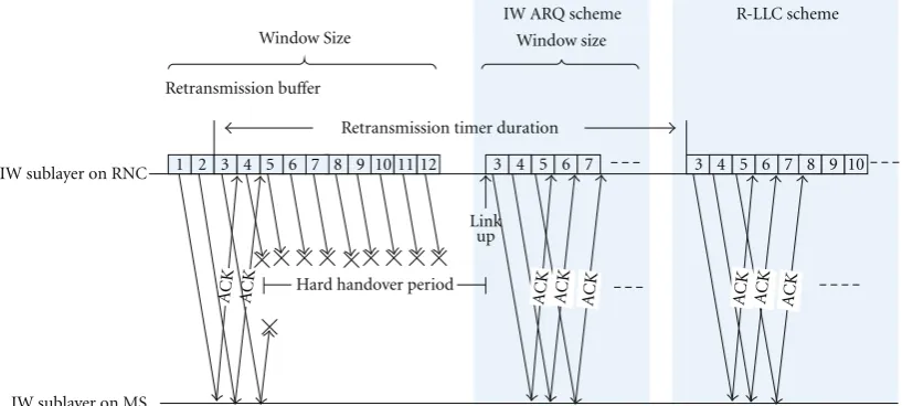
is used for block loss detection and block resequencing in the receiver to guarantee in-sequence delivery. Then, these IW blocks are stored in a local block buffer. When some IW blocks are transmitted through the UMTS or the WiMAX interface according to a retransmission window size, they are also queued in a retransmission queue (Different from conventional retransmission queue definition, in this paper, the retransmission queue refers to the queue that stores transmitted but not acknowledged blocks.) in order to be scheduled for possible retransmission. The IW ARQ transmitter maintains an adaptive retransmission window size that is set to current network buffer size, or wireless BDP size, or simply a default value. When handover begins, IW sublayer just stops transmitting blocks. It segments every incoming packet and keeps blocks in the block buffer. When handover completes (e.g., on receipt of Link Up trigger), IW sublayer resumes block transmission immediately.
On the receiver side, when an IW block is received by the receiver, a positive or negative acknowledgement (ACK/NACK) is sent back immediately for the purpose of reducing handover latency. These received and buffered IW blocks are reordered to form their corresponding packets. Then packets are delivered to upper layer in sequence.
In addition, in order to avoid dead lock due to IW ACK/NACK losses during a handover period, a timer is set when the receiver sends an ACK/NACK. When this timer expires, the receiver sends back a status report (ARQ feedback bitmap) providing the receipt status. This status report is a map of the acknowledgement or negative acknowledgement of each IW block within the window. The status timer duration is set to a default system parameter, for example, 2.5 sec. When an abnormal handover takes place, for example, Link Up trigger is lost or long delayed,
status timer mechanism can eliminate data packet losses after system recovers from this abnormal handover procedure.
Compared with conventional Selective Repeat Request ARQ (SR ARQ) mechanism, the IW ARQ has following new features:
(i) supporting Link Up (LU) trigger: when a MS finishes target network entry procedure, the target network signals the IW sublayer with a Link Up trigger. On receipt of this trigger, the IW sublayer retransmits blocks in retransmit queue to avoid unnecessary waiting for a timeout of status report timer.
(ii) adaptive window size: in order to avoid any buffer overflow in the target network when the IW sublayer retransmits the unacknowledged blocks on Link Up trigger, the IW ARQ retransmission window size can be optionally set to the buffer size or wireless BDP size of the target network.
1 2 3 4 5 6 7 8 9 101112
Retransmission buffer
Window Size
Retransmission timer duration
4
3 5 6 7
Window size
IW ARQ scheme R-LLC scheme
IW sublayer on RNC
IW sublayer on MS
8 9 10
Figure4: IW ARQ and R-LLC: an example of time evolution.
2.4. Signaling and Primitives. Since a new common IW sublayer is introduced to both UMTS and WiMAX systems, the original handover procedures of these systems shall be modified to accommodate the newly added cross-layer primitives. In general, the inter-RAT handover consists of handover preparation phase and handover execution phase. In the case of a handover from UMTS to WiMAX, when the inter-RAT handover conditions, for example, low RSSI or load increase, are met, the MS is instructed by the RNC to perform measurement of target link. Measurement results are reported to RNC in Measurement Reports message. Afterwards, the inter-RAT handover enters into the execution phase if the RNC makes a positive handover decision. In the case of a handover from WiMAX to UMTS, the MS provides measurement report in scanning report message to the network after the scanning period.
The signaling procedure of handover from UMTS to WiMAX is depicted in Figure 5(a). Firstly, based on mea-surement reports and knowledge of the RAN (Radio Access Network) topology, the source RRC (Radio Resource Con-trol) decides to initiate an inter-RAT handover and sends Link Going Down (LGD) trigger to IW sublayer. On LGD trigger from UMTS RRC sublayer, IW sublayer negotiates the location of the dedicated initial ranging transmission oppor-tunity with WiMAX MAC for the MS. When the MS receives handover command from the network, it switch offUMTS transceiver and switch on WiMAX transceivers. Afterwards, upon receipt of Link Up trigger from WiMAX MAC, the IW sublayer resumes block transmission immediately and handover completes.
The handover procedure from WiMAX to UMTS is illustrated inFigure 5(b). Before IW sublayer sends handover request message to source WiMAX MAC, it must demand resource reservation with RRC sublayer for the MS on LGD trigger. Afterwards, the MS is instructed by WiMAX network to switches offWiMAX transceiver and switches on UMTS transceiver. After the MS finishes UMTS radio link setup procedure, the IW sublayer resumes block transmission immediately on Link Up trigger.
Table1: Simulation parameters.
Parameter Setting
IW fragment switch OFF
IW default window size 30 blocks
IW status report timer period 2.5 sec.
UMTS PHY data rate 64, 1024 Kb/s
UMTS PDCP queue length 25
WiMAX queue length 50 blocks
WiMAX PHY data rate 2 Mb/s
TCP variant Reno
TCP MSS 512 bytes
TCP default congestion window 32 segments
TCP minimum RTO timer period 0.2 sec.
Application type FTP
2.5. Simulation Environment and Results. In this section, we present the results of our simulations on NS2 platform. We conduct this simulation to highlight the benefits of IW ARQ context transfer scheme with cross-layer mechanism. The integrated coupling scenario used for simulation analysis is illustrated in Figure 2, and the simulation parameters are shown inTable 1. There is only one MS with two transceivers and no other background traffics in this “clean” scenario. The transmission delay and bandwidth in the wired network are set to 2 ms and 10 Mb/s, respectively. An FTP session is examined, with the CN designated as the sender and the MS designated as the receiver. The FTP session starts at 0.4 sec, and the MS starts performing hard handover at about 4 sec after it enters into the coverage region of WiMAX or UMTS.
2.5.1. Inter-RAT Handover from UMTS to WiMAX. When the inter-RAT handover is from UMTS to WiMAX, at about 4.035 sec the WiMAX network entry procedure is completed and the IW sublayer on the RNC receives a Link Up trigger.
Synchronization confirmation
MS Source RRC(UMTS I/F) Target MAC
(WiMAX I/F) Relocation indication
(Link Going Down)
HO complete indication (Link Up)
Normal operation UMTS I/F
Low RSSI
IW sublayer
Relocation request Measurement
report
HO from UTRAN CMD (UMTS I/F)
WiMAX network entry
Synchronization request
UMTS WiMAX
Inter-RAT handover signaling flow integrated coupling architecture
Switch offUMTS I/F
Switch on WiMAX I/F
Allocate initial Ranging opportunity
(a)
MS (WiMAX I/F)Source MAC Target RRC
(UMTS I/F) HO indication
(Link Going Down)
Relocation confirmation
Normal operation WiMAX I/F
Low RSSI
IW sublayer
HO request Scanning report
Relocation request
BS HO request
HO indication
HO to UTRAN complete UMTS radio link setup
Relocation complete indication (Link Up)
Switch offWiMAX I/F
Switch on UMTS I/F
WiMAX UMTS
Inter-RAT handover signaling flow integrated coupling architecture
Reserve resource
(b)
Figure5: Inter-RAT handover signaling procedures: (a) UMTS→WiMAX; (b) WiMAX→UMTS.
among three kinds of context transfer schemes: R-LLC, SDU Reconstruction, and IW ARQ.
The R-LLC scheme does not support Link Up trigger, so R-LLC retransmits the last unacknowledged block on the timeout of local retransmission timer (retransmission timer period is set to 2.5 sec in our simulation scenario). During this period, the TCP RTO timer expires and the congestion
0 1 2 3 4 5 6 7 8 9
Figure6: TCP congestion window comparison (UMTS data rate 64 kb/s): (a) UMTS→WiMAX; (b) WiMAX→UMTS.
IW sublayer can set its local retransmission window size to the target network’s buffer size when handover is made. On receipt of Link Up trigger, it immediately forwards the IW blocks in its retransmission queue. So, there are no packet losses during handover period.
2.5.2. Inter-RAT Handover from WiMAX to UMTS. When handover is from high-speed WiMAX network to low-speed UMTS network, the buffered TCP segments forwarded from WiMAX to UMTS overflow the UMTS queue in SDU Reconstruction scheme, because the queue in WiMAX may buffer more TCP segments than the queue size of UMTS.
InFigure 6(b), the buffer overflow in UMTS after handover
leads to TCP retransmission starting at about 6.0 sec, and the corresponding TCP window shrinks. In R-LLC scheme, the long local retransmission timer period leads to TCP RTO timer expiration. A segment is retransmitted by TCP sender for three times before this local retransmission timer expires, whereas there are no packet losses in IW ARQ scheme and handover procedure is accelerated thanks to the introduction of Link Up trigger.
3. Cross-Layer between Layer-2 and Layer-4
In the former sections, we apply intersystem retransmission mechanism at common IW sublayer and cross-layer mech-anism between layer-2 sublayers to resolve packet loss and long handover latency problems. In this section, we evaluate and highlight the effects of cross-layer mechanism in resolv-ing typical TCP-specific inter-RAT handover problems, such as BDP mismatch and premature timeout/spurious RTO.
Among the existing inter-RAT handover schemes for TCP traffics, network-centric approaches have the advantage
of being transparent to both TCP sides in comparison with receiver-centric approaches. Furthermore, the snoop proto-col is a TCP-aware link layer scheme, and it can take advan-tage of information from lower sublayers. For these reasons, in this section, we choose the snoop protocol approach as the basis of our inter-RAT handover performance evaluation for TCP traffic. We first propose a snoop agent with new ACK delaying mechanism and cross-layer mechanism. This new snoop agent runs on RNC and is renamed TCP Snoop in this paper. Then through the evaluation, the necessity and effectiveness of cross-layer mechanism between IW sublayer and TCP Snoop are illustrated in resolving TCP-specific handover problems.
In this section, we assume that (1) the only bottleneck in the path of the TCP connections occurs at the RNC/NodeB; (2) The wireless RTT of WiMAX system is smaller than that of the UMTS system. The BDP size of WiMAX system is big-ger than that of the UMTS system; (3) only inter-RAT han-dover from WiMAX to UMTS is considered. Generally, the BDP mismatch and spurious RTO/premature timeouts prob-lems are not severe for handover from UMTS to WiMAX.
IW
Relocation complete indication (from RRC)
Normal operation Relocation
confirmation (from RRC)
TCP sender
ZWA
Data Data
ACK
ACK NZWA (awnd) Handover indication
(MS ID, BDP)
Handover complete indication (MS ID)
Spoofed ACK (awnd) oldWRTT
SWRTT
Triple ACK
(ACK delaying phase ends)
A B TCP Snoop
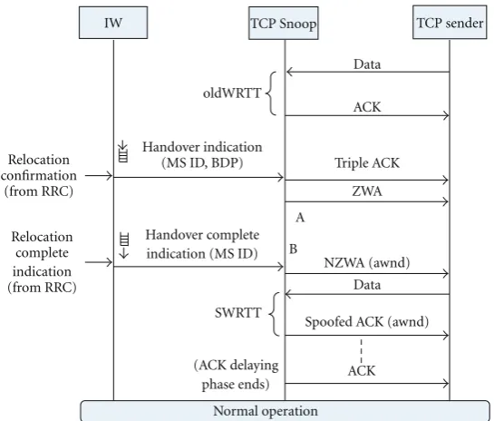
Figure7: Cross-layer primitives between IW sublayer and TCP Snoop.
3.1.1. Handover Preparation. TCP Snoop is disabled when there is no handover. When an inter-RAT handover becomes possible due to, for example, signal strength degradation, TCP Snoop is invoked and informed of current network wireless BDP size by IW sublayer. Afterwards, the TCP Snoop works in the transparent mode. In the transparent mode, a local queue in TCP Snoop is maintained for a TCP connection. This local queue maximal length is set to current network wireless BDP size. Every incoming TCP segment is buffered in this queue and forwarded to the MS as well. When an ACK is from the MS, TCP Snoop not only forwards this ACK to TCP sender but also deletes corresponding TCP segments from this local queue. TCP Snoop may also estimate wireless RTT of current network (oldWRTT in
Figure 7) in terms of the classical Jacobson RTT estimation
algorithm [17].
3.1.2. Handover Execution. When an inter-RAT handover is made, a handover indication primitive is sent from IW sublayer to TCP Snoop (seeFigure 7). In this primitive, the MS and target wireless network BDP sizes are indicated. Depending on the access network wireless BDP size variation after handover, firstly, TCP Snoop may decide to send several triple ACKs to TCP sender. Upon receipt of the triple ACKs, TCP sender reduces congestion window size by half and per-forms fast retransmission. Then, the TCP Snoop sends a Zero Window Advertisement (ZWA) message to the TCP sender to freeze its RTO timer and force it to enter the persist mode.
When a handover complete indication primitive is received from IW sublayer, TCP Snoop resumes segment forwarding to the MS. When the local queue length is below a predetermined length (In our simulation scenario, during handover period, this predetermined length is set to half of wireless BDP size of target network to accelerate
the following ACK delaying procedure.), TCP Snoop sets maximal local queue length to the target network wireless BDP size. Afterwards, TCP Snoop feeds back a Nonzero Window Advertisement (NZWA) message to TCP sender to make it exit persist mode. After that, TCP Snoop enters into ACK delaying phase.
In ACK delaying phase, for every new incoming TCP segment, TCP Snoop creates a corresponding spoofed ACK timer. This timer period (SWRTT) is set to former wireless RTT (oldWRTT) plus an incremental change, as follows:
SWRTT(i)=oldWRTT +a∗oldWRTT∗i, i∈[1, +∞], (1) where oldWRTT is the wireless RTT estimation of the WiMAX link before handover, and the index “i” is the number of spoofed ACK. The constantais set to a very small value deliberately in order to reduce possibility of RTO timer expiration in TCP sender. For example,ais set to 0.05 in our simulation scenario.
When one spoofed ACK timer expires, the TCP Snoop “spoofs” the TCP sender by feeding back a TCP ACK message. In this spoofed ACK message, the advertised window size (Awnd) field is set to current free queue length in the TCP Snoop. This explicit window notification (EWN) mechanism is used to control incoming TCP segment amount to avoid possible buffer overflow in TCP Snoop.
· · ·
Figure8: An example of TCP Snoop working procedure.
0 5 10 15 20 25
TCP Snoop queue length TCP Snoop queue length
TCP Snoop Awnd
Figure 9: The variations of local queue length and advertised
window size (UMTS data rate 64 Kb/s, local queue length 35 after handover).
control mechanism on the sender side that controls TCP transmission rate.
If a new handover is forthcoming when current ACK delaying phase is still in progress, TCP Snoop cancels all spoofed ACK timers and switches back to the transparent mode for this new handover.
The whole cross-layer primitives and messages during handover procedure are described inFigure 7.
3.2. An Example of TCP Snoop Working Procedure. An example of TCP Snoop working procedure is given in
Figure 8. When an inter-RAT handover takes place, the TCP
Snoop receives a handover indication primitive from IW sublayer. On this primitive, TCP Snoop sends triple ACKs to adjust TCP sender congestion window size. Then it sends the ZWA message to the TCP sender to make it enter the persist mode. When layer-2 handover is complete, the IW sublayer sends handover complete indication primitive to TCP Snoop. On this primitive, TCP Snoop continuously forwards stored segments to the MS until its local queue length is below a threshold. In this example, this threshold is set to 2. After that, the TCP Snoop sends the NZWA message to TCP sender to make it exit persist mode. Afterwards, TCP Snoop enters into the ACK delaying phase. When TCP Snoop receives segments from number 20 to 23, corresponding spoofed ACK timers of these segments are created. The period of each spoofed ACK timer is set to former wireless RTT plus an incremental change, as shown in (1). When one of these timers expires, the TCP Snoop feeds back a corresponding spoofed ACK to TCP sender on behalf of MS. The Awnd field of this spoofed ACK is set to free buffer size of local queue in TCP Snoop. When the arrival of the ACK of segment 23 from the MS is before the expiration of this segment’s corresponding spoofed ACK timer in TCP Snoop, ACK delaying phase ends. Subsequently, the TCP Snoop works in a transparent mode or disabled mode.
Note that during handover period, there are no TCP seg-ment losses in the wireless link. Therefore, sequence numbers of spoofed ACKs and sequence numbers of ACKs from MS will not mismatch, thanks to IW sublayer retransmission mechanism.
3.3. Performance Evaluation. The simulation scenario and simulation parameters are, respectively, the same asFigure 2
and Table 1. An FTP session starts at 0.4 s, and the MS
0 5 10 15 20
Figure10: The variations of RTO value in TCP sender (UMTS data
rate 64 Kb/s, local queue length 35 after handover).
informs TCP Snoop of the handover completion. We realize three solutions—normal TCP, Freeze-TCP, and the proposed TCP Snoop in this NS2 simulation platform.
3.3.1. Awnd and TCP Snoop Local Queue. Figure 9shows the
variations of the TCP Snoop local queue length and Awnd size during handover period. In the ACK delaying phase, the queue length looks like a “saw-tooth”—it increases abruptly and decreases at a constant rate. This is because the Awnd size in a spoofed ACK from TCP Snoop limits the amount of segments from TCP sender. TCP sender sends a succession of segments only when TCP Snoop opens up its Awnd size in a spoofed ACK.
At the time 21.5 sec, when an ACK from MS arrives before the expiration of its corresponding spoofed ACK timer at TCP Snoop, TCP Snoop completes current handover procedure—the EWN and ACK delaying mechanisms are disabled. Then, TCP Snoop works in transparent mode or disabled mode.
3.3.2. TCP Snoop Advantages. Figure 10shows RTO
varia-tions of three TCP variants during a handover procedure. Due to long handover latency and abrupt wireless RTT increase after handover, normal TCP suffers from one RTO timer expiration, and congestion window size shrinks to one. After RTO timer expiration, TCP exponential backoff mechanism is invoked and the RTO value doubles.
In Freeze TCP, because of lack of buffer management mechanism and reduced UMTS wireless BDP size, multiple packet losses caused by UMTS buffer overflow after handover also lead to one RTO timeout.
As in the TCP Snoop solution, the EWN mechanism avoids buffer overflow in TCP Snoop and in the target wireless network during a handover period. The ACK
delaying mechanism can gradually increase TCP RTO value and avoid RTO timer expiration. Therefore, thanks to TCP Snoop and IW sublayer, the whole handover procedure is smooth (no spurious RTO) and seamless (no packet losses).
From the above simulation analyses, we can say that TCP Snoop and IW sublayer are reasonable choices for the convergence of future heterogeneous wireless networks.
4. Conclusion
This paper evaluates and highlights the cross-layer effects for the seamless inter-RAT handover between UMTS and WiMAX networks on the basis of the integrated and tight coupling architectures. We first review existing context trans-fer schemes, coupling approaches, TCP-specific handover problems, and IEEE 802.21 MIH framework. Because the standardized MIHF does not specify actual handover exe-cution mechanism, a novel MIHF variant—IW sublayer— is introduced. This common IW sublayer is added on top of PDCP (UMTS) and MAC (WiMAX) sublayers on RNC and MS in the integrated coupling architecture. Thanks to the introductions of intersystem retransmission and cross-layer mechanism, the IW subcross-layer scheme can achieve lossless and prompt handover procedure for UDP traffics. Furthermore, for TCP traffics, on top of IW sublayer, a new TCP Snoop is also introduced on the RNC. With TCP Snoop, the ACK delaying mechanism, explicit window notification mechanism, and cross-layer mechanism are utilized to resolve BDP mismatch and spurious RTO problems that often appear in the inter-RAT handover scenarios. Finally, the simulation results carried out on the NS2 emulator validate the handover performance improvement thanks to the cross-layer mechanism.
References
[1] D. Johnson, C. Perkins, and J. Arkko, “IP Mobility Support in IPv6,” Tech. Rep. 3775 , Internet Engineering Task Force
(IETF), June 2004,http://www.ietf.org/rfc/rfc3775.txt.
[2] G. Lanpropoulos, N. Passas, L. Merakos, and A. Kaloxy-los, “Handover management architectures in integrated
WLAN/cellular networks,” IEEE Communication Survey &
Tutorials, vol. 7, no. 4, pp. 30–44, 2005.
[3] 3GPP, “Technical Specification Group RAN; UTRAN func-tions, examples on signaling procedures, (Realease 7),” Tech. Rep. TR 25.931, V7.4.0.
[4] 3GPP, “Technical Specification Group Radio Access Network; Packet Data Convergence Protocol (PDCP) specification, (Release 7),” Tech. Rep. TS 25.323, V7.5.0.
[5] J. Sachs, B. S. Khurana, and P. M¨ah¨onen, “Evaluation of
handover performance for TCP traffic based on generic
link layer context transfer,” inProceedings of the IEEE 17th
International Symposium on Personal, Indoor and Mobile Radio Communications (PIMRC ’06), pp. 1–5, September 2006. [6] N. Dailly, P. Martins, and P. Godlewski, “Performance
eval-uation of L2 handover mechanisms for inter-radio access
networks,” inProceedings of the IEEE 63rd Vehicular Technology
[7] K. Brown and S. Singh, “M-TCP: TCP for mobile cellular
net-works,”ACM SIGCOMM Computer Communication Review,
vol. 27, no. 5, pp. 19–43, 1997.
[8] M. Meyer, J. Sachs, and M. Holzke, “Performance evaluation
of a TCP proxy in WCDMA networks,”IEEE Wireless
Commu-nications, vol. 10, no. 5, pp. 70–79, 2003.
[9] F. Ren, X. Huang, F. Liu, and C. Lin, “Improving TCP
throughput over HSDPA networks,” IEEE Transactions on
Wireless Communications, vol. 7, no. 6, pp. 1993–1998, 2008. [10] B. Liu, P. Martins, A. E. Samhat, and P. Bertin, “A cross-layer
scheme for inter-RAT handover from WiMAX to UMTS,” in Proceedings of the IEEE Global Telecommunications Conference (GLOBECOM ’08), pp. 1–6, December 2008.
[11] J. C. Moon and B. G. Lee, “Rate-adaptive snoop: a TCP enhancement scheme over rate-controlled lossy links,” IEEE/ACM Transactions on Networking, vol. 14, no. 3, pp. 603– 615, 2006.
[12] J. H. Hu, G. Feng, and K. L. Yeung, “Hierarchical cache design for enhancing TCP over heterogeneous networks with
wired and wireless links,” IEEE Transactions on Wireless
Communications, vol. 2, no. 2, pp. 205–217, 2003.
[13] T. Goff, J. Moronski, D. S. Phatak, and V. Gupta,
“Freeze-TCP: a true end-to-end TCP enhancement mechanism for
mobile environments,” in Proceedings of the 19th Annual
Joint Conference of the IEEE Computer and Communications Societies (INFOCOM ’00), pp. 1537–1545, March 2000. [14] V. Gupta et al., “IEEE802.21 standard and Metropolitan Area
Networks: Media Independent Handover Services,” IEEE std 802.21-2008, January 2009.
[15] B. Liu, P. Martins, A. E. Samhat, and P. Bertin, “A layer 2 scheme of inter-RAT handover between UMTS and WiMAX,” inProceedings of the 68th Semi-Annual IEEE Vehicular Technol-ogy (VTC ’08), pp. 1–5, September 2008.
[16] B. Liu, P. Martins, P. Bertin, and A. E. Samhat,
“Inter-RAT Handover between UMTS and WiMAX,” in Radio
Communications, pp. 1–28, INTECH, 2010.
[17] H. Huang and J. Cai, “Adding network-layer intelligence to mobile receivers for solving spurious TCP timeout during