R E S E A R C H
Open Access
A novel downlink semi-persistent packet
scheduling scheme for VoLTE traffic over
heterogeneous wireless networks
Myasar R. Tabany
1, Chris G. Guy
1and R. Simon Sherratt
2*Abstract
Long-term evolution (LTE) is becoming the first choice of mobile network operators (MNOs) when constructing a wireless network infrastructure because of its high data rate, high throughput, and low latency. These significant advancements are necessary for satisfying the delivery of a wide-range of mobile applications and managed network resources.
However, deploying a new LTE network or a transition from current legacy cellular networks to LTE can take several years to roll out. In the meantime, working in a heterogeneous wireless communication network looks inevitable. This paper investigates Voice over LTE (VoLTE) Quality of Service (QoS) under a heterogeneous wireless communication scenario. The contributions of this paper are twofold. First, a novel downlink (DL) semi-persistent scheduling scheme is proposed to reduce VoLTE end-to-end delay and increase system capacity. Second, an extensive network simulation model has been designed and implemented to evaluate the proposed scheme. The performance of the proposed scheme is compared with the performance of two relevant and well-known DL packet scheduling methods. The simulation results confirm that the proposed scheme is able to reduce VoLTE end-to-end delay and achieve a better system capacity than current methods, and maintain the desired VoLTE QoS.
Keywords:VoLTE, OFDMA, Semi-persistent scheduling, Radio resource management, Quality of Service
1 Introduction
The fourth-generation (4G) long-term evolution (LTE) was standardized by the Third-Generation Partnership Project (3GPP) in Release 8 (R8) technical specification [1]. LTE offers higher data rate, spectral efficiency and multiuser flexibility, and lower latency than the third-generation (3G) Universal Mobile Telecommunications System (UMTS). As a result of these significant im-provements, an explosive growth has started in LTE wireless multimedia traffic, which is characterized by dif-ferent QoS requirements.
The LTE core network, known as the Evolved Packet Core (EPC), lacks native support for circuit-switched (CS) connections. The new technology is all-IP and is a pure packet-switched (PS) domain wireless network. The existence of only a PS domain in LTE has changed the way the application services, including voice, handle this technology. Thus, a new voice service has been launched
compared to the traditional CS-based voice imple-mented in legacy GSM-EDGE Radio Access Networks and Universal Terrestrial Radio Access Networks (GERAN/UTRAN). This new technology, termed Voice over LTE (VoLTE) uses a so-called 3GPP IP Multimedia Subsystem (IMS) with Multimedia Telephony (MMTel) to deliver real high-definition voice (HDV) over LTE networks and a set of Rich Communications Services (RCSs) [2]. This is why this technology is often referred to as Voice over IMS (VoIMS). Unfortunately, the essen-tial steps to deploy this voice technology are too costly and require significant time to roll out. Additionally, many mobile network operators (MNOs) prefer to keep their legacy 2G/3G network infrastructures to deploy IMS and upgrade to 4G LTE networks. Therefore, many interim solutions have been proposed by 3GPP and non-3GPP standard bodies to provide an umbrella platform for voice services before deploying their LTE networks including IMS. The temporary solutions for providing a voice call in LTE are Circuit Switched FallBack (CSFB), Voice over LTE via Generic Access (VoLGA), and
over-* Correspondence:[email protected]
2Department of Biomedical Engineering, University of Reading, Reading, UK
Full list of author information is available at the end of the article
the-top (OTT). Mobile operators will most likely need to deploy one of these intermediate solutions before considering a target VoLTE. On the other hand, mobile operators need several years to deploy their 4G LTE net-works nationwide, and especially in rural areas. During this time, a spotty LTE radio service area will have to interwork with other available Radio Access Technolo-gies (RATs). This interworking should consider many restrictions in terms of the Radio Network Controller (RNC) of the UMTS and evolved NodeB (eNB) of LTE, and the different radio resource management (RRM) techniques between them. The standard Evolved-UTRAN (E-Evolved-UTRAN) interworking with standard 3GPP and non-3GPP wireless networks is shown in Fig. 1 [3]. It is important for the interworking to enable a seamless handover and smooth RAT integration. More import-antly, this interworking should sustain a Quality of Ser-vice (QoS) and Quality of Experience (QoE) for different mobile application services running in between. Specific-ally, real-time (RT) applications with critical and strict QoS constraints on their end-to-end delays and band-width limitations such as VoLTE are important topics in this article.
3GPP specifications offer no guarantee that VoLTE has the ability to fulfill the ITU-R and 3GPP technical require-ments related to QoS, especially with one-way VoLTE end-to-end delay of less than 150 ms and a minimum of 98% VoLTE packet successful delivery. To help with this matter, 3GPP has standardized a new inter-RAT mechan-ism called Single Radio Voice Call Continuity (SRVCC) to
hand over a voice call (and any data sessions) between an Evolved-UTRAN (E-UTRAN—the radio of LTE and LTE-A wireless networks) and any other different technologies [4]. However, consider a scenario when a user initiates a VoLTE call inside an LTE service area and then moves outside the 4G coverage to an area covered by completely different RAT (i.e., GERAN/UTRAN). This scenario poses more significant challenges than only avoiding dropping the voice call. Interoperability between these RATs, sus-taining VoLTE QoS outside the 4G network, provision and management of the required physical Radio Resources (RRs) are needed to be addressed in the design of any scheduling scheme in a heterogeneous communications network. LTE has flat and IP-based network architecture. eNodeB is a base station, which implements all the func-tions previously distributed between the 3G NodeB (NB) and the RNC, and this makes the radio access network in LTE quite simple.
The eNodeB Medium Access Control (MAC) sub-layer contains a packet scheduler which is a highly complex component responsible for scheduling downlink (DL) and uplink (UL) transmissions over the LTE air interface. The scheduler itself runs scheduling algorithms to determine which physical resource assignments are needed for DL/ UL sub-frames to be sent in terms of resource blocks (RBs). An RB occupies 1 slot in the time domain (TD) and 12 sub-carriers in the frequency domain (FD) [5]. The packet scheduler receives inputs from several sources which are then used by scheduling algorithms for imple-menting the QoS characteristics assigned to radio bearers.
hPCRF
The scheduling algorithms in the packet scheduler as-sign RBs based on one of the following methods: Channel-aware and QoS-unaware, channel-unaware, or channel-aware and QoS-aware strategies. The first scheduling strategy assigns RBs based on the wireless channel quality. The user equipment (UE) reports the channel quality to the base station by periodically send-ing Channel Quality Indicator (CQI) feedback. This scheduling strategy has many advantages, mainly the ability to cope with the rapid changes in wireless chan-nel quality in both time and frequency domains. How-ever, it also has its own drawbacks relevant to this work, being the lack of provision for fairness between different users and their application services. It assigns RBs to users with high CQIs, and this can starve other users near cell edges due to their low CQIs. Dynamic schedul-ing defined in LTE protocol stack layer 2 is an example of this scheduling strategy [6, 7]. Dynamic scheduling in-cludes large amount of control signaling which is limited by the number of available Physical Downlink Control Channels (PDCCHs). It can, therefore, decrease VoLTE capacity and, for this reason, would be unsuitable for scheduling voice packets. Persistent scheduling, defined in LTE protocol stack layer 3 is, on the other hand, an important example of the second strategy [8, 9]. Unlike dynamic scheduling, persistent scheduling works by scheduling voice packets on a fixed basis, so no control signaling is required for the PDDCHs for every trans-mission. However, persistent scheduling reserves system bandwidth until the end of the call. It restricts the sys-tem capacity by the maximum syssys-tem delay allowed be-cause a number of retransmissions may be needed. This might increase voice end-to-end delay which makes it an unsuitable scheduling method for VoLTE. Persistent scheduling works without taking the channel quality (CQI feedback) into account and seems unrealistic for VoLTE scheduling. The situation for the first and second scheduling strategies can become even worse when more than one RAT is involved in the process. For all the above reasons, the design of an efficient and QoS-aware resource allocation scheduling scheme which can ad-dress the above issues and improve the network per-formance is crucial to better satisfy end users’ experience based on the application requirements.
The remainder of this paper is structured as follows. Section 2 presents the contributions in this work and briefly highlights the proposed scheme. Section 3 pro-vides an overview of VoLTE, SRVCC, and LTE physical layer. Section 4 introduces the proposed scheduling al-gorithm. Section 5 presents the simulation methodology, setting, and contributed implementation and discusses the simulation results along with a performance com-parison with two well-known scheduling techniques. Finally, the paper concludes in Section 6.
2 Contributions of the work
This article focuses on VoLTE end-to-end delay in a het-erogeneous wireless communication scenario when a VoLTE call initiated in the E-UTRAN and then handed over to a legacy GERAN/UTRAN radio area. A VoLTE inter-RAT handover mechanism is presented that en-ables voice and data sessions continuity between these different radio access technologies based on the 3GPP standardization.
Two original contributions are presented in this work. First, a real VoLTE traffic framework is created that is based on IMS/MMTel which has been accepted as a unified solution at the GSMA mobile world congress 2010, followed by moving a call to a UTRAN radio area. VoLTE gives the ability to conduct voice and data simul-taneously, which is one of the key strengths of this tech-nology. For this reason, this research considered a heterogeneous network of 4G LTE and 3G UMTS. An extensive simulation using the OPNET Modeler Wire-less Suite was created to simulate both 4G LTE network and 3G UMTS (including many scenarios). The coexist-ence scenarios of LTE and UMTS technologies were considered to provide voice call continuity. Details of the simulation network are explained in Section 5. In order to give a realistic scenario, three different RT and non-RT traffic flows were generated with different QoS require-ments and characteristics; VoLTE is delay-sensitive, video conferencing is bandwidth-sensitive, and FTP is loss-sensitive.
A second contribution of this work is the proposal of new DL packet scheduling scheme. The scheduling scheme has been implemented and tested on the designed heterogeneous wireless network. It aims to improve re-source allocation for VoLTE and reduce end-to-end delay caused by fully dynamic and persistent scheduling. The simulation results are compared with the state of the art scheduling methods in the field.
3.1 VoLTE packets transfer from/to E-UTRAN to/from GERAN/UTRAN
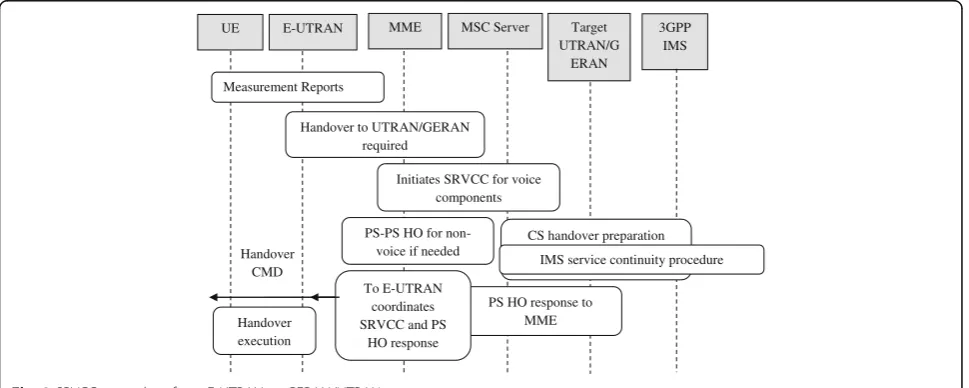
Currently, LTE networks cover only limited areas. Full deployment of this wireless technology is years ahead. It is unlikely for any MNO to provide real VoLTE service to their users even after deploying IMS as at some point, mobiles will need to move to 2G/3G areas and thus have to use CSFB to connect to legacy CS wireless networks. For this reason, SRVCC has been standardized to hand-over a voice call between the E-UTRAN and other RATs to provide service continuity. SRVCC is an efficient inter-RAT handover introduced to support voice call and other data session continuity in 3GPP Release 8 (R8). 3GPP R8 introduces the main technical specifica-tions of SRVCC [4] with many enhancements added later to support emergency call continuity in 3GPP R9 [10] and to support mid-call feature and alerting phase in 3GPP R10 [11]. Furthermore, SRVCC in 3GPP R11 introduces video call continuity with the voice call hand-over ability from GERAN/UTRAN to E-UTRAN known as reverse SRVCC [12]. Generally, the prerequisite for SRVCC is that the UE should initiate a voice call using IMS with an application server (AS) for session transfer in the LTE coverage area and then move to the new RAT coverage area. SRVCC supports UE and IMS ser-vice continuity capabilities with only a single radio ac-cess by the UE at a given time. There is no need for multi-RAT capability for the UE in SRVCC. In case the target legacy network is UTRAN or GERAN (Fig. 1), the Mobile Switching Controller (MSC) server reserves the necessary resources in the CS side to prepare the hand-over procedure as shown in Fig. 2. In parallel, the Mobil-ity Management EntMobil-ity (MME) triggers the session transfer procedure at the Services Centralization and Continuity Application Server (SCC AS). The MME
connects to the MSC server via the Sv interface; the MME uses this interface to start relocation and session transfer. SCC AS needs to enable IMS Centralized Ser-vices (ICS) which are used to set up and control the IMS sessions using CS barriers that are established between the UE and the SCC AS. The 3GPP technical standardi-zations for SRVCC clearly describe service continuity support of this technology to different kinds of legacy wireless networks. However, the complex handover process of SRVCC will vary depending on the target wireless network. Additionally, there are many concerns, not regarding service continuity itself, rather the ability of SRVCC to satisfy QoS requirements for different application services running in the UE, especially RT services with strict delay requirements such as VoLTE.
3.2 LTE physical layer
E-UTRAN has been standardized by 3GPP to be highly scalable and flexible RAT. It supports a range of band-widths, from 1.4 to 20 MHz. 3GPP Release 10 (R10) LTE-Advanced (LTE-A) can provide up to 100 MHz bandwidth support through Carrier Aggregation (CA). LTE-A extends LTE bandwidth by aggregating up to 5 20 MHz channels, which results in higher data rate and system capacity. LTE-based wireless networks employ Or-thogonal Frequency Division Multiple Access (OFDMA) in the DL and Single-Carrier Frequency-Division Multiple Access (SC-FDMA) in the UL.
This work is primarily concerned with the DL direction and so OFDMA receives significant attention. OFDMA is a multicarrier digital modulation scheme that allocates RRs to multiple users based on FD sub-carriers and TD symbols using Orthogonal Frequency Division Multiplex-ing (OFDM). OFDMA allows a wireless network to flex-ibly assign bandwidth and physical resources to a user
Handover CMD
UE E-UTRAN MME MSC Server Target
UTRAN/G ERAN
3GPP IMS
Measurement Reports
Handover to UTRAN/GERAN required
Initiates SRVCC for voice components
CS handover preparation PS-PS HO for
non-voice if needed
IMS service continuity procedure
PS HO response to MME To E-UTRAN
coordinates SRVCC and PS
HO response Handover
execution
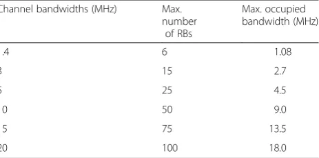
based on the application running, bandwidth needs and/ or the users’ data subscription plan. Thus, OFDMA re-duces power consumption and interference by switching off any unassigned sub-carriers. SC-FDMA is not suitable for the DL direction due to complex receiver architecture, size, and power. SC-FDMA is, however, preferable over OFDMA in the UL direction, as this can lead to a lower peak-to-average power ratio (PAPR) simplifying the design of UE power amplifiers. In the TD, radio resources are al-located every 1 ms and refer to as Transmission Time Interval (TTI) [5]. TTI splits into small frames; each one frame contains 10 consecutive TTIs. In the FD, the total bandwidth is divided into sub-channels of 180 kHz, each with 12 consecutive and equally spaced OFDM sub-carriers. These time/frequency radio resources span two time slots (TSs) in the TD and one sub-channel in the FD known as resource blocks (RBs), the smallest RR unit that can be assigned to a UE for data transmission. The num-ber of symbols in a RB depends on the cyclic prefix (CP) in use. In addition, each TTI is made of two TSs with 0.5 ms; this corresponds to seven OFDM symbols in the default configuration in a short cyclic prefix (SCP) or to six OFDM symbols in the case of the extended cyclic pre-fix (ECP). Different LTE system bandwidths provide differ-ent numbers of RBs (i.e., 15 and 75 RBs for system bandwidths of 3 and 15 MHz, respectively). Table 1 sum-marizes the transmission bandwidth configuration for LTE networks.
4 Scheduling categories in 4G LTE systems
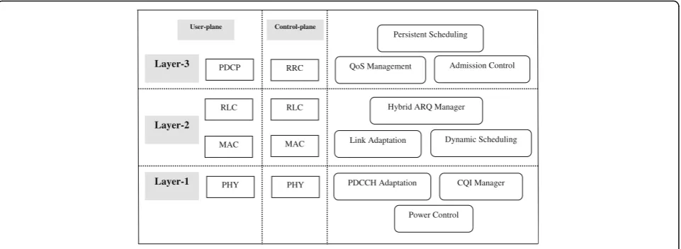
Physical resource blocks (PRBs) are limited in any wire-less network. Many problems occur as a result of allocat-ing these limited resources to a large number of application services, each with different requirements. In LTE, there are two types of scheduling strategies defined in the eNB control and user plane protocol architecture; dynamic scheduling at layer 2 and persistent scheduling at layer 3. Figure 3 shows an overview of the LTE eNB control and user plane and the RRM techniques mapped to each layer.
4.1 Dynamic scheduling
In dynamic scheduling, users’ packets are scheduled every TTI based on the channel quality and are assigned the required Modulation and Coding Scheme (MCS) during link adaptation (LA). Usually CQI information is sent by UEs to the eNBs [6, 7]. In practice, this happens by allocating the required PRBs to the users in a form of grants which are normally sent via PDCCHs. A main drawback of this scheduling is that PDCCHs are limited and for periodic and frequent application traffic like VoLTE, this can add a large amount of control signaling due to the resource request required for each voice packet and this amount of control signaling can increase sharply as the number of users increase, therefore limit-ing system capacity.
4.2 Persistent scheduling
Persistent scheduling, on the other hand, aims to reduce or even eliminate completely the amount of control sig-naling overhead resulting from using a fully dynamic scheduling strategy [8, 9]. It uses a fixed MCS and allo-cates persistent resources for both; a voice call (or burst) and hybrid automatic repeat request (HARQ) retrans-missions (for both time and frequency domains). It may be possible to implement persistent scheduling with no HARQ retransmissions allocation required at all, rather voice packets are sent a fixed number of times. This al-location continues until the UE receives a new alal-location in the case of a new channel condition and/or voice codec is changed. Capacity in the context of persistent scheduling is not limited by the PDDCHs. The main drawback of this scheduling strategy is that it wastes re-sources or allocates fewer rere-sources than required be-cause it lacks the channel information when making scheduling decisions. This is also due to the unexpected number of transmissions between different users, which could decrease system capacity. In addition, any packet transmission failure in persistent scheduling would re-quire retransmitting these packets again in a dynamic way by using dynamic scheduler.
4.3 Proposed downlink semi-persistent scheduling scheme
4.3.1 Overview
The desired goal of this work is to propose a scheduling scheme to improve VoLTE traffic resource allocation by reducing end-to-end delay increased by using other scheduling strategies (i.e., dynamic scheduling). In addition, LTE has been specified to support thousands of voice users. Fully persistent scheduling limits system capacity and therefore, the proposed scheme from this research aims to support higher capacity on the PDCCH. For this purpose, the proposed scheme focuses mainly on the VoLTE traffic in a mix of RT and non-RT cellular Table 1LTE transmission bandwidth configuration
traffic environments. Traditionally, voice is a periodic communication service. This means that voice packets arrive periodically and frequently, and the inter-arrival time is constant based on the voice codec. For the Adap-tive Multi-Rate (AMR) voice codec, packets arrive every 20 ms during the talk period, termed active periods. However, there are some silence periods when users are quiet. During inactive periods, a Silence Indicator or Si-lence Insertion Descriptor (SID) is sent every 160 ms, termed silence periods. Silence periods typically utilize more than half the time of any voice call (for some cases such as calling any customer service center, it might take quite more than this time). This was the first idea of the proposed scheme. The second idea is to propose semi-persistent scheduling (SPS). This scheduling combines the advantages of both dynamic and persistent schedul-ing in order to achieve better system capacity and reduce control signaling. Only a few SPS scheduling schemes for LTE and LTE-A systems have been proposed in the literature [13, 14] [15–17]. Fan et al. [16, 17] presented the idea of SPS and enhanced version of SPS without packet bundling to enhance the overall system perform-ance through increase DL system capacity, which can positively affect the UL direction at the same time. The significant results of these works using an LTE system level simulator show that the proposed technique has the ability to increase LTE system capacity and decrease the required control signaling overhead compared to a fully dynamic scheduling. However, the literature has not considered the heterogeneity scenario of a wireless network when a VoLTE call needs to be handed over from an E-UTRAN to different RATs. SPS uses both strategies in different transmission stages; persistent scheduling used during an initial transmission and dynamic scheduling used for the rest (HARQ retrans-mission). The proposed scheduling scheme is further ex-tended by considering talk spurt features of voice. SPS
scheduling is proposed to reduce the control signaling compared to a fully dynamic scheduling. For an applica-tion like VoLTE with periodic and small packet sizes, the overhead would be unacceptable if every scheduling allo-cation is individually signaled resulting in the control channel signaling needing higher bandwidth than neces-sary. Although SPS can be designed and configured for only DL or UL, or for both DL and UL transmission di-rections, the former has been considered in this work by considering the DL transmission. The standard G.711 pulse-code modulation (PCM) voice codec has been im-plemented as an encoder scheme. For this reason, 20 ms has been chosen for the talk spurt length (for both in-coming and outgoing talk spurt), while a 160 ms has been chosen for the silence length [18]. As illustrated in Fig. 4, during active periods of 20 ms, a voice encoder generates a voice packet with 31 bytes payload, in addition to 9 bytes overhead for compressed RTP/UDP/ IP and RLC headers added to each voice packet. During inactive periods of 160 ms, only 15 bytes are transmitted in the SID instead of voice packets.
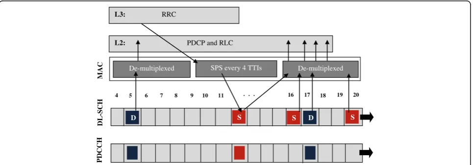
The PDDCH is used to carry the cell radio network temporary identifier (C-RNTI), a typical dynamic UE identifier. The C-RNTI indicates that the next downlink resource has been demultiplexed by the MAC and passed on to higher layers and is now scheduled for this UE. C-RNTI is unique for the current cell and changed through an updating procedure when UE accesses a new cell. Once SPS implemented and/or configured by the eNB, this identifier is replaced by SPS-RNTI and the UE receives an allocation using this new identifier. This allocation is an SPS scheduling allocation and so would be repeated according to SPS pre-configured periodicity (in the form of SPS-RNTI, period). MCS and the num-ber of RB assignments all remain the same within one SPS allocation. However, HARQ retransmissions, once needed, will be separately scheduled using a dynamic
Control-plane
Layer-1 Layer-2 Layer-3
User-plane
PDCP RRC
RLC
MAC
RLC
MAC
PHY PHY
QoS Management Admission Control
Hybrid ARQ Manager
Dynamic Scheduling
PDCCH Adaptation CQI Manager Persistent Scheduling
Link Adaptation
Power Control
scheduler. An example of SPS-scheduling which uses dy-namic scheduling for retransmission is explained in Fig. 5.
The only scenarios to change the fixed SPS allocation (including the MCS and the number of RB assignment) to a new one sent by PDDCH is when the radio channel conditions change or a current SPS allocation is deacti-vated (release SPS) using RRC downlink control infor-mation (DCI). Only DCI 1A is used for the SPS release purpose (without releasing RRC configuration). Special fields for SPS activation and release for PDCCH valid-ation are illustrated in Tables 2 and 3 [19].
According to 3GPP TS 36.213 [19], A UE shall validate an SPS assignment PDCCH only if all the following con-ditions are met:
1. The cyclic redundancy check (CRC) parity bits obtained for the PDCCH payload are scrambled with the SPS C-RNTI.
2. The new data indicator field is set to“0.”In case of DCI formats 2, 2A, 2B, and 2C, the new data
indicator field refers to the one for the enabled transport block.
The validation procedure for activating, deactivating, and releasing SPS is explained in section 9.2 of the 3GPP standard [19]. In the SPS scheduling of VoLTE packets, the scheduler is switched off during silence pe-riods. The proposed scheme gives high priority to SPS scheduling over default dynamic scheduling.
The implementation of the proposed scheduling scheme in the designed wireless network is as follows: every time the DL scheduler is run, it checks whether any SPS UEs are due in that particular sub-frame. If true, then SPS UEs submit to the DL scheduler as they have high priority over dynamic UEs.
As this work considers three different application ser-vices implemented in the heterogeneous wireless network (VoLTE, video conferencing, and FTP), then it is import-ant to consider the scenario of how the network can de-cide which application packets have to be assigned SPS
15 Bytes
40 Bytes
Hea
der
Payload
(3
1
By
te
s)
Hea
der
Payload
(3
1
Bytes)
Hea
der
Payload
(31 Bytes)
20 ms 160 ms
Active Talk-Spurt Inactive Silence Periods (SID packets)
. . . . .
Fig. 4Illustration of active and inactive periods for voice traffic
16
DL-SCH D S D S
17 18 5 6 7 8 9 10 11
PDCCH
MAC
L2: PDCP and RLC
De-multiplexed SPS every 4 TTIs De-multiplexed
L3: RRC
20 19 4
S
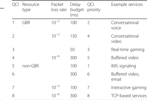
scheduling (i.e., VoLTE packets) and when scheduling should start. The LTE QoS Class Identifier (QCI) specifies the class to which the bearer belongs. Table 4 illustrates the standard LTE QoS classes. The QoS in the evolved packet system (EPS) is based on the data flow concept and bearers. Such flows of data are established between the UE and the Packet Data Network Gateway (PDN-GW) and mapped to bearers, with three individual bearers (Radio, S1 and S5/S8). The combinations of them provide the end-to-end QoS support to LTE.
4.3.2 Downlink scheduler and frame generation
In this proposed scheme, the DL scheduler generates the MAC Protocol Data Units (MPDUs) of a DL sub-frame at the eNBs and filling a UL grant with the data of active bearers at the UEs. It also assigns signaling bearers, such as bearers carrying IMS signaling and protocol packets always having higher priority over any other data bearers. Guaranteed Bit Rate (GBR) bearers (e.g., VoLTE in this work) always have higher priority over other non-GBR bearers (e.g., Email). It is worth noting that IMS signaling is the only exception to this rule as a non-GBR bearer has higher priority over GBR bearers with QCI = 5 (see Table 4). For all GBR bearer traffic, and since their
radio bearers are accepted only through an Admission Control (AC), then the frame capacity is expected to be sufficient to handle all of them with any remaining frame capacity given to non-GBR bearers based on their priority levels. The non-GBR bearers are then serviced based on their QCI values. If non-GBR bearers have the same QCI, then they will be serviced using a fairness scheduling algorithm and the available resources are then shared equally among these bearers and data. An exceeded traffic limit of GBR bearers may exist (if found) due to underestimation of RLC and MAC layer overheads or due to a higher than expected load from higher layers. In such cases, and to keep a reasonable level of fairness between different types of traffic, this traffic is served by the scheduler in the same way as the traffic on non-GBR bearers is served. Additionally, this procedure is applied after all the non-GBR bearers’traffic has been handled.
The DL sub-frame is shared between the PDCCH and the Physical Downlink Shared Channel (PDSCH). There-fore, if the PDCCH takes two symbol times, then the remaining space is given to the PDSCH and this can in-crease the amount of available slots for data. Note that the number of symbol times allocated to PDCCH depends on the number of Control Channel Elements (CCEs) in that Table 2Special fields for SPS activation PDCCH validation
DCI format 0 DCI format 1/1A DCI format 2/2A
TPC command for scheduled PUSCH Set to“00” N/A N/A
Cyclic shift DM RS Set to“000” N/A N/A
MCS and redundancy version MSB is set to“0” N/A N/A
HARQ process number N/A FDD: set to“000”
TDD; set to“0000”
FDD: set to“000”TDD; set to“0000”
MCS N/A MSB is set to“0” For the enabled transport
block; MSB is set to“0”
Redundancy version N/A Set to“00” For the enabled transport
block; set to“00”
Table 3Special fields for SPS release PDCCH validation
DCI format 0
DCI format 1A
TPC command for scheduled PUSCH
Set to
“00”
N/A
Cyclic shift DM RS Set to
“000”
N/A
MCS and redundancy version Set to
“11111” N/A
Resource block assignment and hopping resource allocation
Set to all
“1”s
N/A
HARQ process number N/A FDD: set to“000” TDD; set to“0000”
MCS N/A Set to“11111”
Redundancy version N/A Set to“00”
Resource block assignment N/A Set to all“1”s
Table 4LTE standard QCI classes
QCI Resource
1 GBR 10−2 100 2 Conversational
voice
2 10−3 150 4 Conversational
video
3 50 3 Real-time gaming
4 10−6 300 5 Buffered video
5 non-GBR 100 1 IMS signaling
6 300 6 Buffered video,
7 10−3 100 7 Interactive gaming
sub-frame. All retransmissions are scheduled dynamically. A DCI is created on the PDCCH to signal the HARQ process ID for the retransmission element. HARQ retrans-missions use the same MCS as the original transmission, even when adaptive MCS is supported.
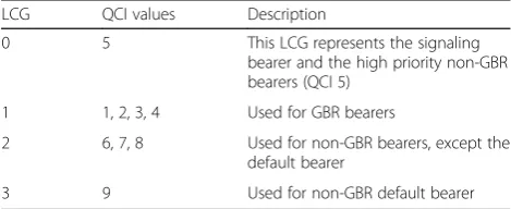
The maximum number of HARQ retransmissions in the proposed scheme is set to three. In some cases, seg-mentation of the larger voice packets into smaller packet segments is required and this can give a better SPS scheduling performance, especially if the available PRBs are insufficient for these large packets. In this work, seg-mentation has been used to convert any large voice packets into a new stream of fixed-sized packets with the packet size set to three by the available PRBs. UEs in the proposed scheme send Buffer Status Reports (BSRs) and Channel Quality Indicator feedback in the UL to their serving eNBs. Logical Channel Groups (LCGs) are four groups and each group has its own ID of 0–3. The mapping of the bearers to these four LCGs for the pur-pose of buffer status reporting is based on the QCI values of the bearers. Table 5 illustrates the QCI to LCG standard mapping for BSR used by the OPNET Modeler [13]. The proposed scheduling scheme was analyzed and compared with the well-known scheduling methods in the literature being channel-dependent scheduling (CDS) and Modified Weighted Round Robin (MDRR_WRED); further details are presented in Section 5.2.
5 Simulation design and performance evaluation A heterogeneous wireless network model was created to evaluate the proposed work. The model was divided into a number of nodes that carry the LTE and UMTS protocols and functions. OPNET Modeler Wireless Suite was used as a tool to develop the model, as can be seen in Fig. 6.
5.1 Simulation design
The simulation of the heterogeneous network contained two wireless networks. The UMTS network consisted of two UMTS base stations (NBs:
umts_node_b_3sector_sli-p_adv), there were 16 mobile stations (UEs:umts_wkstn)
in each NB (total of 32 UEs in the UMTS network), one Serving GPRS Support Node (SGSN:
umts_sgsn_etherne-t_atm_slip9_adv) in addition to the UMTS Radio
Net-work Controller (RNC: umts_rnc_amt2_eth2_slip2_adv)
node. The number of the LTE UEs in the simulation sce-nario is smaller than the work in [16]. However, the simulator software, simulation constraints and parame-ters, number of application services running over these LTE UEs, and most importantly, the heterogeneity of the wireless network are all different.
The LTE network consisted of five LTE base stations (eNBs:lte_enodeb_atm4_ethernet4_slip4_adv), with 9 mo-bile stations (UEs:lte_wkstn_adv) in each eNB (total of 45 UEs in the whole LTE network), one IP Multimedia Sys-tem (IMS) in addition to the LTE core network (EPC:
lte_epc_atm8_ethernet8_slip8_adv). Table 6 shows the
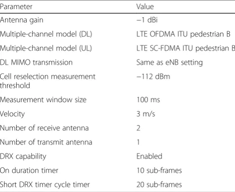
im-portant configuration parameters of the LTE UEs. The path loss (PL) model in each UE was implemented as [20]:
PL dBð Þ ¼ 128:1þ 37:6 log10D; ð1Þ
whereDis distance in kilometer. The designed hetero-geneous wireless network also contained Application Definition, Profile Definition, Mobility Management configuration, IP QoS parameters, and LTE configur-ation entities. In addition, a number of wired and wire-less links were used to connect between nodes. The link model used to connect the two different wireless net-works was a point-to-point advanced link (ppp_adv,
SONET/OC192). LTE EPC was connected to the UMTS
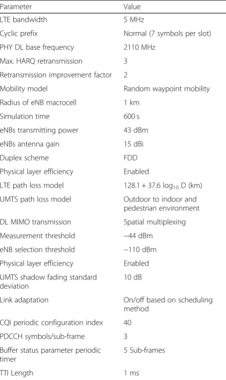
network to serve as a UMTS Gateway GPRS Support Node (GGSN). In the designed network, only one EPC node was allowed to work as an EPC in the whole net-work and GGSN and EPC; therefore, it could not have different IDs. The network main parameters are summa-rized in Table 7. Mobility was implemented with a node velocity of 3 m/s. The UEs transmission power (w) was set to cover the cell size with DRX enabled using the same cell DRX parameters. The 5 MHz frequency div-ision duplexing (FDD) bandwidth was chosen for the physical profile in the LTE network.
In order to give a very realistic heterogeneous network scenario, the work considered a typical network located in London, UK, with a 1 km eNB radius. UEs were ran-domly distributed between eNBs. In the designed net-work, the eNBs, NBs, SGSG, UEs, and EPC were programmed to have unique IDs and names.
The IMS model was used to deliver HDV and a set of RCSs in order to represent a realistic scenario in delivering the VoLTE service. The IMS model consisted of Proxy Call Session Control Function (P-CSCF), Serving-CSCF (S-CSCF), and interrogating-CSCF (I-CSCF). These components were used for the signaling procedures of the VoLTE calls between different users in the network. The EPC was one entity which included all the main required core network parts; the Mobility Manage-ment Entity (MME), the Serving Gateway (S-GW), and the Packet Data Network Gateway (PDN-GW). Table 5QCI-LCG mapping for buffer status reporting
LCG QCI values Description
0 5 This LCG represents the signaling
bearer and the high priority non-GBR bearers (QCI 5)
1 1, 2, 3, 4 Used for GBR bearers
2 6, 7, 8 Used for non-GBR bearers, except the default bearer
Internally, the voice packets were sent over real-time protocol (RTP) streams. Traffic was generated in the network model only when the application is active; therefore, the traffic duration equaled the simulation duration.
5.2 Results and discussion
This section evaluates the performance of the proposed novel downlink scheduling scheme. The results are eval-uated and compared with two widely accepted trad-itional scheduling methods for wireless networks, being CDS and MDRR_WRED. The results are evaluated in terms of three main QoS factors; capacity, end-to-end delay, and packet loss ratio (PLR) in addition to the sys-tem throughput. The simulation results presented in this work have been plotted based on time change until the end of the simulation time. Further simulation scenarios have been worked out and plotted different results based on the number of users. These results show that load can directly impact service quality and the higher the number of UEs gives the lower the QoS and can nega-tively cause serious degradation in service quality pro-vided to end user when reach very high number depending on the MCS used.
5.2.1 Effects on VoLTE capacity
The main goal of any scheduling algorithm in wireless networks is to maximize system capacity while keeping the QoS requirements to a great extent. VoIP capacity is
Fig. 6Overview of the heterogeneous wireless network simulation model
Table 6User equipment configuration parameters
Parameter Value
Antenna gain −1 dBi
Multiple-channel model (DL) LTE OFDMA ITU pedestrian B
Multiple-channel model (UL) LTE SC-FDMA ITU pedestrian B
DL MIMO transmission Same as eNB setting
Cell reselection measurement threshold
−112 dBm
Measurement window size 100 ms
Velocity 3 m/s
Number of receive antenna 2
Number of transmit antenna 1
DRX capability Enabled
On duration timer 10 sub-frames
defined as the number of users that could be supported in a sector without exceeding 5% outage guaranteeing that at least 95% of the users would be satisfied when the system load was reached. A user is considered to be in outage, if during the call at least one short-term win-dow of length 10 s is regarded as a bad quality. The short term window is regarded as bad quality if more than 5% of the packets are lost (i.e., either erroneous or discarded) [21].
Figure 7 illustrates VoLTE capacity of the heteroge-neous wireless network for different scheduling methods. In any cellular system, capacity is determined mainly by the MCS index. However, scheduling, HARQ and LA can all play a major role in the system perform-ance and voice capacity. It is clear from the results in Fig. 7 that the proposed scheme outperforms other scheduling methods and provides much higher voice capacity gain than others. For the 5 MHz FDD mode of LTE, the VoLTE capacity using MCS20 was 69 VoLTE users, 58 users for MCS15, 32 users for MCS9, 15 users
for MCS4, and 6 users for MCS0. The result also shows that both CDS and MDRR_WRED scheduling have al-most similar capacities.
5.2.2 Effects on VoLTE end-to-end delay
VoLTE end-to-end delay or a so-called mouth-to-ear voice delay is one of the most important factors to con-sider when evaluating the VoLTE QoS. VoLTE has a very tight delay requirement which should be strictly main-tained under limits and must be carefully monitored. End-to-end delay is measured from the ingress of the UE at the sender side to the egress of the UE at the re-ceiver side. In the simulated network, VoLTE end-to-end delay can be expressed as:
VoLTE end to end delay
¼ Network delay þ Encoding delay þ Decoding delay þ Compression delay
þ Decompressiondelay þ Dejitter buffer delay
ð2Þ
According to ITU and 3GPP standard recommen-dations [22, 23], one way mouth-to-ear VoLTE delay should be less than 150 ms. However, a delay budget of up to 250 ms is still acceptable if 100 ms extra delay required for packet processing and propagation delay in the congestion core network is considered. Up to 50 ms is the delay bound allowed for radio access network from eNB to UE. This delay bound has been chosen for the 3GPP performance evalua-tions to better account for variability in network end-to-end delays [8]. Figure 8 presents a compari-son of the average VoLTE end-to-end delay between the different scheduling methods used in the simula-tion networks. The average VoLTE delay of 160 ms was recorded from the proposed scheme compared Table 7Wireless network configuration parameters
Parameter Value
LTE bandwidth 5 MHz
Cyclic prefix Normal (7 symbols per slot)
PHY DL base frequency 2110 MHz
Max. HARQ retransmission 3
Retransmission improvement factor 2
Mobility model Random waypoint mobility
Radius of eNB macrocell 1 km
Simulation time 600 s
eNBs transmitting power 43 dBm
eNBs antenna gain 15 dBi
Duplex scheme FDD
Physical layer efficiency Enabled
LTE path loss model 128.1 + 37.6 log10D (km)
UMTS path loss model Outdoor to indoor and pedestrian environment
DL MIMO transmission Spatial multiplexing
Measurement threshold −44 dBm
eNB selection threshold −110 dBm
Physical layer efficiency Enabled
UMTS shadow fading standard deviation
10 dB
Link adaptation On/off based on scheduling method
CQI periodic configuration index 40
PDCCH symbols/sub-frame 3
Buffer status parameter periodic timer
5 Sub-frames
TTI Length 1 ms
to 178 and 170 ms for the CDS and MDRR_WRED scheduling respectively. The reported VoLTE end-to-end delays from all the scheduling methods are slightly higher than the one in [16]. This is due to the different application traffic running over the LTE UEs and considering the traffic crossing through dif-ferent wireless technologies of LTE and UMTS as well which includes extra delay. The results also indicate that the semi-persistent proposed scheme was able to reduce VoLTE end-to-end delay and keep it within the acceptable limits. However, the proposed scheme did not make a significant contribution to reduce VoLTE end-to-end delay due to the use of dynamic scheduling for the retransmission, which clearly re-sulted in a higher packet loss ratio (explained in Sub-section 5.2.3). In addition, the proposed scheduling considers the talk spurts and silence periods of VoLTE and uses a priority-based procedure to select if the traffic needs semi-persistent or other scheduling method which can include extra delay.
5.2.3 Effects on packet loss ratio
Packet loss ratio (PLR) is another important VoLTE QoS factor to examine and reveal system performance. PLR generally refers to the percentage of packets that are lost during the transition from the sender to the receiver in the wireless network. Ideally, in any steady state net-work, there should be no voice packet loss. However, practical packet transmission in wireless networks will include a considerable amount of packet loss and this is why the HARQ technique is used in these networks. The failure of voice packets to arrive at the destination side will degrade voice quality and result in a poor end user experience. However, voice users are still typically satisfied if the PLR is less than 2% based on the 3GPP
standard requirements [23]. In this network, PLR is expressed as:
Packet loss rate
¼ ðVoice traffic sent–Voice traffic receivedÞ =Voice traffic sent 100%
ð3Þ
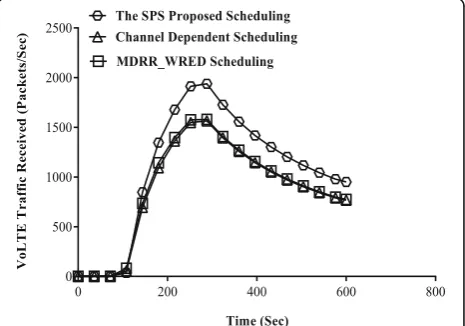
Figure 9 demonstrates VoLTE traffic received when applying different scheduling methods. The traffic re-ceived is an indication of the number of packets dropped during the transmission when it is compared with the traffic sent, and therefore, it refers to the VoLTE packet loss rate in the simulation scenario. The higher the VoLTE traffic received is the lower the VoLTE packet loss rate. It is clear from the result that voice traffic re-ceived from the proposed scheme has the highest traffic level between all other scheduling methods. Overall, the average voice traffic received for the proposed scheme was 1336 packet/s compared to 1068 packet/s and 1087 packet/s for the CDS and MDRR_WRED respectively.
5.2.4 Effects on system throughput
The proposed scheme is designed to reduce VoLTE delay, control signaling, and packet loss while also achieving rea-sonable throughput and fairness. The scheduling method used directly impacted the throughput of the system, and the system throughput was strongly influenced by the end-to-end performance.
Throughput refers to the average number of packets successfully received or transmitted by the receiver or the transmitter channel per second. The overall eNodeB throughput of different scheduling methods is plotted in Fig. 10. CDS scheduling assigns physical resources to users with best channel quality and so provides a higher throughput than the other schemes. Assigning resources to users with high channel and link qualities provide ex-cellent eNB throughput. However, this comes at the cost
Fig. 8VoLTE end-to-end delay (s)
of fairness between these users running different appli-cations. On the other hand, MDRR_WRED assigns phys-ical resources sequentially and without taking channel and link quality into account, which results in the best fairness scenario between users, but at the cost of the worst eNB throughput. The trade-off between these two factors has been extensively studied in literature based on various methods. The proposed scheme gives high cell throughput and keeps fairness between users to a high extent while it gives users with VoLTE application running in their UEs higher priority.
6 Conclusions
Next generation wireless networks are required to trans-port and manage a wide range of applications with di-verse traffic requirements and characteristics. 3GPP has developed an exclusive QoS framework and a set of radio resource management techniques for this purpose. However, 3GPP technical specifications do not define any specific scheduling algorithms to support these real time and non-real time applications. As a result, a var-iety of scheduling algorithms have been proposed in the last few years. In this paper, a novel downlink semi-persistent scheduling scheme for heterogeneous commu-nication networks is proposed and comprehensively evaluated. The results demonstrate that the proposed scheme outperforms other well-known packet schedul-ing methods. It provides a lower packet loss ratio and higher capacity and reduces VoLTE end-to-end delay ac-cordingly. The proposed scheme supports a special pref-erence to VoLTE and its strict delay requirements. Nevertheless, it guaranteed fairness between all the dif-ferent applications to a satisfactory level.
Acknowledgements
This work was partially supported by Riverbed Technologies Ltd., through providing the required OPNET Modeler Wireless Suite licenses for this work and the University of Reading, UK.
Funding
The tools for this research work were supplied by Riverbed Technologies Ltd. The Open Access funding was supplied by the University of Reading.
Authors’contributions
All authors contributed to the work. All authors read and approved the final manuscript.
Competing interests
The authors declare that they have no competing interests.
Publisher’s Note
Springer Nature remains neutral with regard to jurisdictional claims in published maps and institutional affiliations.
Author details
1Wireless Communications Research Lab, School of Systems Engineering,
University of Reading, Reading, UK.2Department of Biomedical Engineering,
University of Reading, Reading, UK.
Received: 1 August 2016 Accepted: 13 March 2017
References
1. 3GPP TS 36.300, LTE; Evolved Universal Terrestrial Radio Access (E-UTRA) and Evolved Universal Terrestrial Radio Access Network (E-UTRAN); Overall description; Stage 2, Release 8, v8.12.0, April 2010.
2. 3GPP TS 23.228, Digital cellular telecommunications system (Phase 2+); Universal Mobile Telecommunications System (UMTS); LTE; IP Multimedia Subsystem (IMS); Stage 2, Release 8, v8.12.0, March 2010.
3. 3GPP TS 23.402, Universal Mobile Telecommunications System (UMTS); LTE; Architecture enhancements for non-3GPP accesses, Release 8, v8.10.0, March 2012. 4. 3GPP TS 23.216, Digital cellular telecommunications system (Phase 2+);
Universal Mobile Telecommunications System (UMTS); LTE; Single Radio Voice Call Continuity (SRVCC), Stage 2, Release 8, v8.8.0, March 2012. 5. 3GPP TS 36.211, LTE; Evolved Universal Terrestrial Radio Access (E-UTRA);
Physical channels and modulation, Release 8, v8.9.0, January 2010. 6. P Kela, J Puttonen, N Kolehmainen, T Ristaniemi, T Henttonen, M Moisio,
Dynamic packet scheduling performance in UTRA long term evolution downlink. Paper presented at the IEEE 3rd International Symposium on Wireless Pervasive Computing, Santorini, Greece, 7-9 May 2008.
7. Y Fan, M Kuusela, P Lundén, M Valkama, Downlink VoIP support for evolved UTRA. Paper presented at the IEEE Wireless Communications and Networking Conference, Las Vegas, NV, 31 March-3 April 2008. 8. J Puttonen, N Kolehmainen, T Henttonen, M Moisio, Persistent packet
scheduling performance for Voice-over-IP in evolved UTRAN downlink. Paper presented at the IEEE 19th International Symposium on Personal, Indoor and Mobile Radio Communications, Cannes, 15-18 September 2008. 9. F Capozzi, G Piro, LA Grieco, G Boggia, P Camarda, Downlink packet
scheduling in LTE cellular networks: Key design issues and a survey. IEEE Communications Surveys & Tutorials 15(2), 678–700 May 2013. 10. 3GPP TS 23.216, Digital cellular telecommunications system (Phase 2+);
Universal Mobile Telecommunications System (UMTS); LTE; Single Radio Voice Call Continuity (SRVCC), Stage 2, Release 9, v9.9.0, March 2012. 11. 3GPP TS 23.216, Digital cellular telecommunications system (Phase 2+);
Universal Mobile Telecommunications System (UMTS); LTE; Single Radio Voice Call Continuity (SRVCC), Stage 2, Release 10, v10.6.0, June 2013. 12. 3GPP TS 23.216, Digital cellular telecommunications system (Phase 2+);
Universal Mobile Telecommunications System (UMTS); LTE; Single Radio Voice Call Continuity (SRVCC), Stage 2, Release 11, v11.11.0, July 2014. 13. J Liu, C Hu, Z Ma, K Zheng, W Wang, Semi-persistent scheduling for VoIP
service in the LTE-advanced relaying networks. Paper presented at the IEEE International Conference on Communications, Circuits and Systems, Chengdu, 28-30 July 2010.
14. S Saha, R Quazi, Priority-coupling-a semi-persistent MAC scheduling scheme for VoIP traffic on 3G LTE. Paper presented at the 10th International Conference on Telecommunications,Zagreb, 8-10 June 2009.
15. D Jiang, H Wang, E Malkamaki, E Tuomaala, Principle and performance of semi-persistent scheduling for VoIP in LTE system. Paper presented at the IEEE International Conference on Wireless Communications, Networking and Mobile Computing, Shanghai, 21-25 September 2007.
16. Y. Fan, P. Lundén, M. Kuusela, M. Valkama, Efficient semi-persistent scheduling for VoIP on EUTRA downlink. Paper presented at the IEEE 68th Vehicular Technology Conference, pp. 1-5, Alberta, 21-24 September 2008. 17. Y Fan, M Valkama, Enhanced VoIP support in OFDMA-based packet radio
networks. Wireless Personal Communications 66(2), 343–366 (2012) 18. 3GPP R2-071743, Further considerations on DL semi-persistent scheduling,
Nokia & Nokia Siemens Networks, RAN2#58, Kobe, Japan, May 2007. 19. 3GPP TS 36.213, LTE; Evolved Universal Terrestrial Radio Access (E-UTRA);
Physical layer procedures, Release 9, v9.3.0, October 2010.
20. 3GPP TR 25.814, Technical Specification Group Radio Access Network; Evolved Universal Terrestrial Radio Access (E-UTRA); Physical layer procedures), Release 7, v7.1.0, September 2006.
21. 3GPP R1-070674, LTE physical layer framework for performance verification, Orange, China Mobile, KPN, NTT DoCoMo, Sprint, T-Mobile, Vodafone, Telecom Italia, TSG-RAN1#48, St. Louis, MI, USA, February 2007. 22. ITU-T Recommendation G.114, One way transmission time, 2003. 23. 3GPP TS 23.203, Technical Specification Group Services and System Aspects;
PCC, Release 10, v10.6.0, March 2012.
Submit your manuscript to a
journal and benefi t from:
7Convenient online submission
7Rigorous peer review
7Immediate publication on acceptance
7Open access: articles freely available online 7High visibility within the fi eld
7Retaining the copyright to your article
![Fig. 1 E-UTRAN interworking with 3GPP and non-3GPP wireless networks [3]](https://thumb-us.123doks.com/thumbv2/123dok_us/932099.1113275/2.595.57.537.457.712/fig-utran-interworking-gpp-non-gpp-wireless-networks.webp)