R E S E A R C H
Open Access
Low-complexity quantize-and-forward
cooperative communication using two-way
relaying
Iancu Avram
*, Nico Aerts and Marc Moeneclaey
Abstract
Cooperative communication is used as an effective measure against fading in wireless communication systems. In a classical one-way cooperative system, the relay needs as many orthogonal channels as the number of terminal it assists, yielding a poor spectral efficiency. Efficiency is improved in two-way relaying systems, where a relay simultaneously assists two terminals using only one timeslot. In the current contribution, a two-way quantize-and-forward (QF) protocol is presented. Because of the coarse quantization, the proposed protocol has a low complexity at the relay and can be used with half-duplex devices, making it very suitable for low-complexity applications like sensor networks. Additionally, channel parameter estimation is discussed. By estimating all channel parameters at the destination terminals, relay complexity is kept low. Using Monte Carlo simulations, it is shown that the proposed QF protocol achieves a good frame error rate (FER) performance as compared to two-way amplify-and-forward (AF) and one-way relaying systems. It is further shown that, using the proposed estimation algorithm, the FER degradation arising from the channel parameter estimation is negligible when compared to an (unrealistic) system in which all parameters are assumed to be known.
Keywords: Cooperative communication; Two-way relaying; Estimation; Sensor networks; Diversity
1 Introduction
Cooperative telecommunication systems can effectively be used to combat fading by exploiting the broad-cast nature of the wireless medium [1-6]. In a classical cooperative communication system, only unilateral munication is considered: one transmitting terminal com-municates to one receiving terminal with the help of a relaying terminal. Many practical applications however require bilateral communication, in which two terminals both send and receive information to/from each other. Using a classical (one-way) cooperative system in this sit-uation would yield a poor spectral efficiency, as this would require four orthogonal channels, i.e., the two transmit-ting terminals need one channel each, and the relay trans-mits over two channels that the data received from the first and second terminal, respectively. The spectral effi-ciency can be improved using a two-way relaying system,
*Correspondence: [email protected]
Department of Telecommunications and Information Processing (TELIN, UGent), St-Pietersnieuwstraat 41, 9000 Ghent, Belgium
in which the relay uses a single channel to simultane-ously assist in the information transfer from the first to the second terminal and from the second to the first terminal. As for one-way cooperative systems, a variety of for-warding protocols have been developed for two-way sys-tems, including, but not limited to, network coding [7,8], amplify-and-forward (AF) [9], decode-and-forward (DF) [9,10], and compress-and-forward (CF) [11]. While many of these protocols achieve satisfactory results regarding outage probability and frame error rate (FER), they also impose a (large) burden upon the relay in terms of com-putational complexity and/or storage space requirements. The DF strategy requires the relay to decode the received data. In the AF protocol, the relay needs to store the analog signals awaiting retransmission, requiring a high-precision analog-to-digital conversion (i.e., many quanti-zation bits per sample) and, therefore, a large memory to store the samples.
Two-way quantize-and-forward (QF) protocols have been studied in [12] and [13]. In [13], the capacity of a
two-way relaying channel is maximized using an informa-tion theoretical approach. Channel symmetry is assumed, i.e. both users’ channel qualities need to be the same, both in the uplink and downlink. In [12], a two-way QF relaying scheme using space-time block coding (STBC) is proposed. The two transmitting nodes use STBC to simul-taneously transmit their signals to the relay, where they are estimated by using minimum mean square error-ordered successive interference cancellation (MMSE-OSIC). The main drawback of the proposed system is the MMSE-OSIC algorithm that needs to be executed at the relay, inevitably raising its complexity. Furthermore, the relay is required to have multiple antenna’s, also raising its hard-ware cost. Both [12] and [13] also assume that there is no direct link between the two user terminals, making it impossible to exploit cooperative diversity.
These hardware requirements can limit the usefulness of existing two-way relaying strategies in applications requiring a low relay complexity, such as sensor networks and battery powered devices. Therefore, in the current contribution, a low-complexity two-way relaying strategy is presented, based on the QF protocol. The main goal is to keep the relay complexity to a minimum by shifting as much operations as possible to the user terminals, where typically there is more processing power available. While QF protocols with a low relay-side complexity have been developed for one-way relaying systems [14,15], the adap-tation of these protocols to two-way relaying systems is not straightforward. In the current paper, a novel two-way QF protocol is introduced and its performance is ana-lyzed. The proposed protocol exploits cooperative diver-sity, by assuming there is a direct path between the user terminals. Furthermore, a practical estimation scheme is proposed for the estimation of all the unknown channel parameters. In order to limit the relay complexity to a minimum, all estimation is performed at the destination terminals, with no additional calculations needed at the relay.
The remainder of this paper is organized as follows: The channel model is outlined in Section 2, whereafter the
proposed quantization scheme is presented in Section 3. In Section 4, the receiver structure is obtained and in Section 5, the estimation algorithm is discussed. The FER performance of the proposed algorithms is analyzed using Monte Carlo (MC) simulations in Section 6. Finally, conclusions are drawn in Section 7.
Notations
Bold lower- and uppercase letters are used to denote vec-tors and matrices, respectively. The absolute value and phase of the complex number x are denoted as|x| and arg(x)∈(0, 2π), respectively. The Hermitian transpose of
x is denotedxH and the suffix modMis used to denote
the modulo-M reduction to the interval [0, M). The
notationp(x|y;z)refers to the probability density function (pdf ) of the random variablex, conditioned on the ran-dom variable y, with z denoting a known deterministic parameter of the considered pdf.
2 Channel model
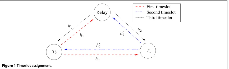
In this contribution, a cooperative two-way relaying scheme is analyzed consisting of two terminals exchang-ing information, denoted T0 and T1, and one assisting relay, denotedR. At bothT0andT1, the information to be transmitted is divided into frames ofK-coded bits, which are obtained by encoding the information bits by means of a channel encoder. The terminalsT0,T1, andR trans-mit in turn using time-division multiple access (TDMA), as depicted in Figure 1. At T1 (T0), the signals received from the relay and fromT0(T1) are combined in order to retrieve the information sent byT0(T1).
All channels are modelled as flat Rayleigh fading chan-nels with additive white Gaussian noise. We denote the complex-valued channel gains between T0 and T1, between T0 and R, and between R and T1 as h0, h1, andh2, respectively. The gains of the reciprocal channels are denoted h0, h1, and h2, respectively, as also shown in Figure 1. In order to keep the discussion general, no assumptions are made on the relation between the fading gains of reciprocal channels. Denoting byc0,c1, andcr, the
PSK symbol sequences sent byT0(first slot),T1(second slot), andR(third slot), respectively, the channel outputs for the information transfer fromT0toT1are equal to
r0= slot),R(first slot), andT1(third slot), respectively. Simi-lar expressions hold for the reciprocal signals. Assuming the normalization condition |c0|2 = |c1|2 = |cr|2 = K, the quantities E0, E1, and Er denote the
transmit-ted energy per symbol atT0, T1, andR, respectively. All channel coefficients are considered to be constant dur-ing a frame and have a zero-mean circular symmetric complex Gaussian (ZMCSCG) distribution with variances
Nhx = 1/dx
nloss,x ∈ {0, 1, 2}. The quantityd
x represents
the distance between the two considered terminals, while
nloss denotes the path loss exponent. The components of
the noise vectorsnx are also ZMCSCG distributed with
variancesNx,x∈ {0, 1, 2}.
3 Two-way relaying
In the following subsections, the operation performed at the relay is discussed, assuming that the symbols transmit-ted byT0andT1belong to aM1-PSK constellation, with
M1as the constellation size. This operation results in the symbol vectorcrtransmitted by the relay in the third slot.
An AF two-way relaying strategy, to be used for bench-marking the performance of the proposed QF system, is briefly discussed first.
3.1 Amplify-and-forward
In a two-way relaying AF system, the relay simply adds the signals received from T0 andT1 and transmits a scaled version of the resulting sum. This yields the following expression forcr:
cr =β
In order to satisfy the normalization constraint
E|cr|2
Note that the relay in a two-way AF system needs to know the squared channel magnitudes|h1|2and|h2|2.
3.2 Quantize-and-forward
A straightforward implementation of a two-way QF relay-ing system that is similar to the AF relayrelay-ing system would
involve the coarse quantization of the sum of the sig-nals received in the first and second slot from T0 and
T1, respectively, and the broadcasting of these quantized samples in the third slot. While the initial purpose of quantization is to avoid the storage of analog samples, this approach however would require the relay to store the analog samples received fromT0in the first slot, until the data fromT1 is received in the second slot and the two can be added and quantized. Instead, a quantization scheme that does not necessitate the storage of analog values is proposed, where the relay separately quantizes the signals received in the first and second slot and then properly combines the quantized values. This involves the following operations, which do not require any channel knowledge at the relay.
3.2.1 Quantization
In the first and second slot, the phase of the samples received fromT0andT1, respectively, is quantized uni-formly using log2M2bits. When takingM2 ≥ 2M1, this approach has shown to yield a performance close to that of AF for one-way relaying systems [14]. The uniform quan-tization, with log2M2 bits, of the phases of the signals
r1(k)andr2(k)received by the relay yields the quantized able to exploit circular symmetry at the relay, we impose thatM2is a multiple ofM1.
3.2.2 Addition
The quantized phases ofr1(k) andr2(k) are added, and the resulting sum determines the symbolcr(k)to be sent
by the relay in the third slot. Introducing the mapping function
the symbols sent by the relay can be written as
cr(k)=χM2
the components of q1 and q2 are represented by only log2M2bits. The memory usage can further be lowered in a practical implementation by storing the elements of
q1 obtained in the first slot, performing the moduloM2 addition element-wise in the second slot as the values of
q2become available by quantizing the incoming signalr2, and storing the result of the addition back inq1. The latter is then mapped onM2-PSK symbols using Equation 2 and broadcast in the third slot.
The number of computations that the relay needs to perform is also limited. The quantization operation has a low complexity, as only the phase of the incoming signals is quantized, neglecting the amplitude. This complexity is further lowered by only considering uniform quantiza-tion. The modulo-M2addition of the resulting quantiza-tion intervals involves the addiquantiza-tion of two integers with a limited range and is thus easily implemented in hard-ware. Channel parameter estimation does not add to the computational burden of the relay, because all channel parameters are estimated at the destination terminals.
4 Likelihood calculation
AtT1 (T0), the signals received from the relay and from
T0(T1) need to be combined in order to optimally retrieve the information bits sent byT0(T1). In this section, we will focus on the calculation of the likelihoods of the received symbols atT1, which are used by the channel decoder at
T1to detect the information bits transmitted byT0. Simi-lar expressions are obtained for the symbol likelihoods at
T0, used to detect the information transmitted byT1. The symbol likelihoods atT1are given by
p(r0,r2|c0,h0,h1,h2,h2;c1)=p(r0|c0,h0)
×pr2|c0,h1,h2,h2;c1
, (3)
As T1 knows the symbols c1, Equation 3 denotes the likelihood ofc0based on the observationsr0andr2, and c1is to be considered as a known parameter. Evaluating Equation 3 on a symbol-by-symbol basis and conditioning on the symbols sent by the relay yields
pr0,r2|c0,h0,h1,h2,h2;c1= Equation 4, further on referred to as the transition prob-abilities, one has to take into account that due to the moduloM2addition, there are multiple combinations of
q1(k) andq2(k) that all give rise to the same relay sym-bol cr(k). This yields the following expression for the
transition probabilities:
Let us introduce the functionf, describing the pdf of the received phase when a symbol of amplitude 1 and phase 0 is sent over an AWGN channel with a signal-to-noise ratio (SNR) equal toγ [14], which is given by
f(θ;γ )= 1
which completes the calculation of the symbol likelihoods.
5 Estimation
The likelihoods calculated in the previous section depend on the specific realization of the channel coefficientsh0,
h1,h2, andh2 (for the likelihoods calculated atT0) andh0,
The channel coefficients that need to be estimated can be divided into two groups: the ones that are directly observed byT1(these areh0andh2) and the ones that are not (these areh1andh2). The main difficulty is estimat-ing the parameters that are not directly observed. In order to keep the complexity at the relay terminal low, we delib-erately choose not to perform any relay-side estimation. However, due to the quantization performed at the relay, it is quite difficult to estimate the channel coefficientsh1 andh2 at T1. Fortunately, this problem can be circum-vented by directly estimating the transition probabilities used in Equation 4, so that we no longer need to know the specific values of h1 andh2. Indeed, in [16], it was shown that the source-relay transition probabilities can be estimated at the destination in a one-way quantize-and-forward system. Accurate results were obtained by first estimating the transition probabilities using pilot symbols transmitted by the source and then iteratively refining these pilot-based estimates by also using the a poste-riori probabilities of the unknown data symbols in the estimation process.
In the one-way relaying system described in [16], the transition probabilities only depend on the symbols
trans-mitted by T0 and on the channel between T0 and R.
However, in the two-way system at hand, they also depend
on the symbols sent byT1and on the channel between
T1 and R, which makes the estimation more complex.
In order to be able to apply the results from [16] to the considered two-way system, we first group the transition probabilities from Equation 5 into the three-dimensional arrayT, of which the elements are defined as
T(q,m,n)=P[cr=χM2(q)|c0=χM1(m),h1,h2;
c1=χM1(n)] . (8)
The symbol indexkis omitted from Equation 8 because, due to the slow fading nature of communication channels, the elements ofTdo not depend on the position within a frame. Note thatTcontains a total ofM1×M2×M2 ele-ments, all of which need to be estimated. For higher-order mapping constellations, it can be a problem to estimate all elements ofTindividually, as this would require very long frames and a vast number of pilot symbols.
Fortu-nately, the number of elements from T which actually
need to be estimated can be reduced to onlyM2by exploit-ing the inherent circular symmetry ofT. Indeed, defining ¯
t(q)=T(q, 0, 0)withq=0, 1,. . .,M2−1, it can be easily shown from Equations 5, 6, and 7 that
T(q,m,n)= ¯t
q−M2(m+n) M1
modM2
, (9)
which indicates that, for the givenmandn, the elements {T(q,m,n),q= 0, 1,. . .,M2−1}are obtained as a cyclic shift of the vectort¯= ¯(t(0),. . .,¯t(M2−1))over(m+n)MM21 positions.
In order to assist the estimation ofh=(h0,h2,¯t), both
T0 and T1 transmit pilot symbols which are known to
both terminals. These pilot symbols are quantized at the relay using the same quantization method as was used for the data symbols. Hence, the relay operation does not need to distinguish between data symbols and pilot sym-bols. Using the pilot symbols, an initial estimate ofhis be obtained atT1. This pilot-based estimate ofhis then iter-atively refined using code-aided estimation that exploits also the presence of the unknown data symbols contained inr0andr2 . The reader is referred to Appendix A and [16] for more details regarding this estimation procedure, which makes use of the expectation-maximization (EM) algorithm.
6 Performance results
The frame error rate (FER) performance of the proposed protocol is investigated using Monte Carlo simulations. We consider frames of 1,024 information bits, encoded by means of an (1, 13/15)8 RSCC turbo code [17] that is punctured to a rate of 2/3, yielding a total of 1,536 coded bits which are then mapped on binary phase-shift
keying (BPSK) symbols (M1 = 2). At the relay, 2-bit
quantization of the phase of the received samples is used, yielding transmitted relay symbols belonging to a quadra-ture phase-shift keying (QPSK) constellation (M2 = 4). The path loss exponent equals 4 and the distance between
T0 andT1are considered unity. All symbol energies are considered to be equal (E0 =E1 =Er) and all noise
vari-ances are also assumed to be equal (N0 = N0 = N1 =
N1 = N2 =N2). In the remainder of this section, perfor-mance metrics related to the information transfer fromT0 toT1are considered. Results for the communication in the opposite direction are obtained by simply interchanging the positions ofT0andT1.
6.1 Channels and transition probabilities known
In this subsection, the FER performance of the proposed two-way relaying system is analyzed under the assumption that the relevant channels and transition probabilities are known at the receiving terminal. This FER performance is compared to that of a non-cooperative system and a classical one-way relaying system. For a fair comparison, we require the three systems to operate at the same spec-tral efficiencyRb/Rs, withRbandRsdenoting the average
information bitrate and the symbol rate, respectively. This is achieved by dimensioning the systems as indicated in Figure 2:
• In the two-way relay system, we use three slots to send 1,024 information bits in each direction (2,048 information bits in total), yielding a total
transmission time of 2,048/Rband a duration of
Figure 2Timeslot assignment for one-way and two-way relaying systems.
the turbo code is punctured to a rate of2/3, yielding 1,536 coded bits (1,536 BPSK symbols) in the first slot and in the second slot and 1,536 QPSK symbols in the third slot (i.e., 3×1536=4,608 symbols in total). The resulting spectral efficiency isRb/Rs=4/9
information bits per channel use.
• In the non-cooperative system, there are only two slots as no relay is involved in the communication process. Each slot has a duration of 1,024/Rb, which is
3/2 times the slot duration of the two-way relay system. The spectral efficiency ofRb/Rs=4/9 is
obtained by puncturing the turbo code to a rate of
4/9(instead of6/9for the two-way relaying systems), yielding 2,304 coded bits (2,304 BPSK symbols) per slot (i.e., 2×2,304=4,608 symbols in total).
• In the one-way relay system, the relay uses two slots, to forward the information fromT0toT1and from
T1toT0, requiring a total of four slots, each of
duration 512/Rb. The turbo code is punctured to a rate of8/9(instead of6/9for the two-way relaying systems), yielding 1,152 coded bits (1,152 BPSK symbols) in the first and the third slot and 1,152 QPSK symbols in the second and in the fourth slot
(i.e., 4×1,152=4,608 symbols in total), again resulting in a spectral efficiency ofRb/Rs=4/9.
Also note that, while the above three communication systems yield the same spectral efficiency, the relay in a one-way relaying system needs to transmit more sym-bols (and thus consume more energy) as compared to the relay in a two-way relaying system. Indeed, in a one-way relaying system, the relay is active during two slots, trans-mitting a total of 2,034 symbols. In a two-way relaying system, the relay is only active during one slot, transmit-ting a total of 1,536 symbols. This favors the two-way relaying system in applications where low relay energy consumption is required, such as battery-powered sensor networks and on-body relaying networks.
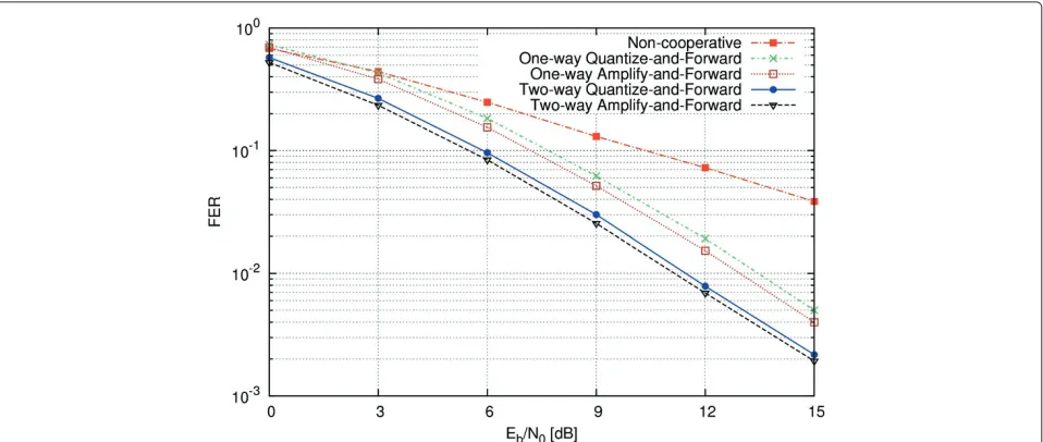
The FER performance of the considered relaying proto-cols is shown in Figure 3 as a function of theEb/N0ratio. The quantity Eb is used to represent the energy needed to transmit (and relay) 1 information bit from T0to T1. The relay position is varied uniformly on a line connect-ingT0andT1(i.e. in each frame, a random relay position is selected). The figure shows that the proposed two-way QF system achieves a good FER performance that is only
slightly worse than for the way AF system. Both two-way systems outperform their one-two-way counterparts and due to the increased diversity, all the cooperative systems clearly outperform the non-cooperative system.
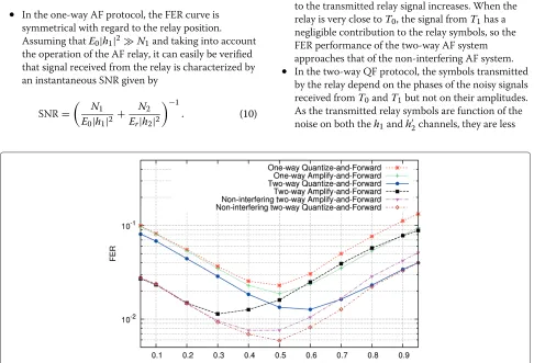
In Figure 4, the position of the relay is varied on a line connectingT0andT1, while theEb/N0ratio is kept fixed at 9 dB. The resulting FER values are shown as a function of the normalized distance betweenT0and the relay. In order to better understand the FER behavior of the two-way protocols shown in Figure 4, the FER per-formance of a two-way AF and QF system in which the relay ignores the signal from T1 is also shown. These configurations will be referred to as non-interfering AF and non-interfering QF, respectively. Because the relay ignores the contribution fromT1, the sole contribution in the signal transmitted by the relay stems fromT0. In the non-interfering QF (AF) system, the first and third slot support a one-way QF (AF) protocol betweenT0andT1 in which the relay only assistsT0, while the second slot supports a single-diversity information transfer fromT1 toT0. The following observations can be made from the aforementioned figure:
• In the one-way AF protocol, the FER curve is symmetrical with regard to the relay position. Assuming thatE0|h1|2N1and taking into account
the operation of the AF relay, it can easily be verified that signal received from the relay is characterized by an instantaneous SNR given by
SNR=
N1
E0|h1|2+
N2
Er|h2|2
−1
. (10)
BecauseN1/E0=N2/Er, as specified in the
beginning of this section, Equation 10 is symmetrical with respect to|h1|2and|h2|2, implying the
symmetry of the FER curve.
• Due to the coarse quantization at the relay, the one-way QF protocol is outperformed by one-way AF. The degradation of the former with regard to the latter is negligible when the relay is located close to
T0, but increases when their distance gets larger,
because of the decreasing SNR on theh1channel. • In the two-way AF protocol, the relay transmits a
scaled version of the sum of the signals received from
T0andT1, such that the sum signal has a given energy
per symbol interval. As the resulting contribution fromT0to the transmitted relay symbols is smaller
than in the case of non-interfering AF (in which the contribution fromT0is the sole contribution),
two-way AF is outperformed by non-interfering AF. The degradation of the two-way AF system with regard to the non-interfering AF system decreases when the relay moves in the direction ofT0, because
in the former system the weight of the signal fromT0
to the transmitted relay signal increases. When the relay is very close toT0, the signal fromT1has a
negligible contribution to the relay symbols, so the FER performance of the two-way AF system approaches that of the non-interfering AF system.
• In the two-way QF protocol, the symbols transmitted by the relay depend on the phases of the noisy signals received fromT0andT1but not on their amplitudes.
As the transmitted relay symbols are function of the noise on both theh1andh2channels, they are less
reliable than in the non-interfering QF system; therefore, non-interfering QF outperforms two-way QF. The degradation of the two-way QF system with regard to the non-interfering QF system decreases when the relay gets closer toT1, because of the
increasing SNR on theh2channel. When the distance between the relay andT1is very small, the noise on
theh2channel can be ignored, yielding the same situation, and thus the same FER performance, as the non-interfering QF system.
The FER plots from Figure 4 show that, depending on the position of the relay with respect toT0andT1, two-way QF clearly outperforms two-two-way AF and vice versa. When sufficient relay resources are available to support a two-way AF protocol, the results from Figure 4 can be used to determine which protocol is best suited to yield the lowest FER (on average) for the information trans-fer from T0 to T1 for a given relay position. Of course, for the same relay position, the selected protocol may not be optimal for the information transfer from T1 to T0, so trade-offs will have to be made. When we have the freedom to select the position of the relay, we achieve maximum fairness (information transfer from T1 to T0 and fromT0toT1yield the same FER) when the relay is located halfway betweenT0andT1; for this relay position, the two-way QF system slightly outperforms the two-way AF system whenEb/N0= 9 dB.
6.2 Channels and transition probabilities estimated Here, we consider the FER performance of the two-way QF relaying system, when the relevant channel gains and
transition probabilities are estimated by the destination terminal. In order to assist the estimation, 20 pilot sym-bols are added to the data frames at bothT0andT1, so that each slot now consists of 1,556 symbols. The pilot
symbols added byT0do not need to equal those added
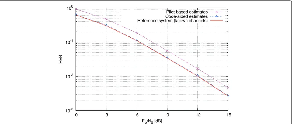
byT1, but both pilot symbol sequences need to be known to both terminals. The pilot-based estimates of the tran-sition probabilities and ofh2are computed using five EM iterations, while the code-aided refining is executed using eight EM iterations. In the code-aided approach, the EM iterations and turbo decoding iterations are merged as explained in [18]. Using this technique, the increase in complexity induced by the code-aided estimation process is minimal. Figure 5 shows the FER performance of the proposed QF system resulting from pilot-aided estimation and code-aided estimation.
We observe that pilot-based estimation yields a signifi-cant degradation with respect to the reference system in which all channel parameters are assumed to be known. This degradation is however almost completely mitigated using the code-aided approach, yielding essentially the same FER performance as the reference system. These results prove that the proposed two-way relaying QF sys-tem is suitable to be used in real-life syssys-tems, because efficient estimation of the unknown channel parameters can be achieved.
7 Conclusions
In this contribution, an implementation has been pro-posed for a two-way QF relaying system. The compu-tational complexity at the relay has been kept low, in order to make the proposed algorithm suitable for relaying
Figure 5FER performance of a two-way QF system with estimated channel parameters.FER performance of a two-way QF system in which the unknown channel parameters are estimated using different estimation techniques, as function of theEb/N0ratio for a relay position that is
networks with hardware constraints at the relay, such as sensor networks. After presenting a closed-form expres-sion for the symbol likelihoods at the receivers, the estimation of the unknown channel parameters was dis-cussed. In order to keep the relay complexity low, all parameters are estimated at the destination, requiring no additional operations from the relay. The performance of the proposed algorithms for a relay position that is uni-formly distributed between the transmitting and receiving terminal was subsequently evaluated using Monte Carlo simulations. It was shown that the considered two-way QF system clearly outperforms both one-way systems and non-cooperative ones. It was further shown that the FER degradation with respect to a two-way AF system, which has a much higher relay-side complexity, is very low through the full SNR range. In order to gain more insight into the proposed algorithm, the effect of the relay position was also investigated and the results were explained. Finally, it was shown that the proposed esti-mation algorithms yield only a negligible degradation in FER as compared to an (unrealistic) system in which all channel parameters are assumed to be known, making the presented QF protocol and estimation algorithms suit-able to be used in real-life networks that require a low relay-side complexity.
Appendix A
AtT1, the channel coefficientsh0andh2and the transi-tion probabilities¯tneed to be estimated. In [16], channel parameter estimation using the EM algorithm was dis-cussed for a one-way QF system. These results will now be extended to a two-way QF system. The EM algo-rithm is an iterative algoalgo-rithm that, besides using the known pilot symbols, also uses the unknown data sym-bols in the estimation process. These unknown variables are referred to as nuisance parameters. In the case at
hand, data symbols transmitted byT0 and the symbols
transmitted by the relay are considered to be nuisance parameters.
One EM iteration consists of an expectation step and a maximization step. In the expectation step, the estimates
from the previous iteration are used to compute the a
posterioriexpectation of the nuisance parameters. In the maximization step, these expectations are used to update the channel estimates. Introducing h = h0,h2,¯t, the expectation step during iterationiconsists of calculating the following Q-function (i−1)-th EM iteration. The maximization step involves
finding the value of h that maximizes this Q function, yielding where the value ofhˆ(0)is initialized using the pilot-based estimates.
Using a similar reasoning as in [16], it can be shown that the elements ofhˆ(i)are equal to
withKpthe number of pilot symbols and
u(0i−1)(k)= thea posterioriprobability of the symbolc0(k)based on the estimatehˆ(i−1), i.e.,
These a posteriori probabilities are provided by the channel decoder atT1.
The code-aided EM algorithm is initialized using pilot-based estimates ofhˆ0,hˆ2, andtˆ, denoted ashˆ0p,hˆ2p, andˆtp,
respectively, so thathˆ(00) = ˆh0p,hˆ2(0) = ˆh2p, andtˆ(0) =ˆtp.
the pilot symbol positions asc0p,c1p,r0p, andr2p,
respec-tively, the pilot-based estimates in thei-th EM iteration are given by respectively. The initial conditions for the pilot-based EM algorithm are set toh(20p)=1 andp(0)(q)=1/M2, ∀q.
Competing interests
The authors declare that they have no competing interests.
Acknowledgements
The authors wish to acknowledge the Agency for Innovation by Science and Technology Flanders (IWT) that motivated this work. This research has been funded by the Interuniversity Attraction Poles Programme initiated by the Belgian Science Policy Office.
Received: 1 August 2014 Accepted: 7 November 2014 Published: 21 November 2014
References
1. B Sklar, Rayleigh fading channels in mobile digital communication systems part I: characterization. IEEE Commun. Mag.35(7), 90–100 (1997) 2. TM Cover, JA Thomas,Elements of Information Theory(Wiley, New York,
1991)
3. A Sendonaris, E Erkip, B Aazhang, User cooperation diversity - part I: system description. IEEE Trans. Commun.51(11), 1927–1938 (2003) 4. TM Cover, A El Gamal, Capacity theorems for the relay channel. IEEE Trans.
Inf. Theory25(5), 572–584 (1979)
5. A El Gamal, M Mohseni, S Zahedi, Bounds on capacity and minimum energy-per-bit for AWGN relay channels. IEEE Trans. Inf. Theory52(4), 1545–1561 (2006)
6. JN Laneman, Ph. D. thesis, Cooperative diversity in wireless networks: algorithms and architectures. Massachusetts Institute of Technology (2002)
7. P Larsson, N Johansson, K Sunell, Coded bi-directional relaying. IEEE Vehic. Technol. Conf. (VTC 2oo6-Spring)2, 851–855 (2006)
8. P Popovski, H Yomo, inProc. IEEE ICC. Physical network coding in two-way wireless relay channels (Glasgow, 2007)
9. B Rankov, A Wittneben, Spectral efficient protocols for half-duplex fading relay channels. IEEE J. Sel. Areas Commun.25, 379–389 (2007)
10. S Bagheri, F Verde, D Darsena, A Scaglione, Randomized
decode-and-forward strategies for two-way relay networks. IEEE Trans. Wireless Commun.10(12), 4214–4225 (2011)
11. P Zhong, M Vu, inProc. Allerton Conference on Communication, Control, Computing and Urbana-Champaign,Compress-forward without Wyner-Ziv binning for the one-way and two-Way relay channels, (IL, USA, Sep. 2011), pp. 426–433
12. RM Legnain, RHM Hafez, ID Marand, AM Legnain, inProc. IEEE Canadian Conference on Electrical & Computer Engineering (CCECE),Two-way quantize-and-forward relaying with STBC, (Montreal, Canada, 2012), pp. 1–5
13. M Heindlmaier, O Iscan, C Rosanka, inProc. IEEE International Symposium on Information Theory (ISIT),Scalar quantize-and-forward for symmetric half-duplex two-way relay channels, (Istanbul, Turkey, 2013), pp. 1322–1326
14. M Souryal, H You, Quantize-and-forward relaying with M-ary phase shift keying. IEEE Wireless Commun. Netw. Conf, 42–47 (2008).
doi:10.1109/WCNC.2008.13
15. I Avram, N Aerts, D Duyck, M Moeneclaey, A novel quantize-and-forward cooperative system: channel estimation and m-psk detection performance. EURASIP J. Wireless Commun. Netw. Article ID 415438, 11 (2010)
16. I Avram, N Aerts, H Bruneel, M Moeneclaey, Quantize and forward cooperative communication: channel parameter estimation. IEEE Trans. Wireless Commun.11(3), 1167–1179 (2012)
17. S Lin, D Costello,Error Control Coding, 2nd edn. (Pearson Education Inc., 2004)
18. N Noels, C Herzet, A Dejonghe, V Lottici, H Steendam, M Moeneclaey, M Luise, L Vandendorpe, inProc. IEEE ICC,Turbo-synchronization: an EM algorithm approach, (Anchorage, 2003)
doi:10.1186/1687-1499-2014-194
Cite this article as:Avramet al.:Low-complexity quantize-and-forward cooperative communication using two-way relaying.EURASIP Journal on Wireless Communications and Networking20142014:194.
Submit your manuscript to a
journal and benefi t from:
7Convenient online submission
7 Rigorous peer review
7Immediate publication on acceptance
7 Open access: articles freely available online
7High visibility within the fi eld
7 Retaining the copyright to your article