R E S E A R C H
Open Access
MPCM: a hardware coder for super slow
motion video sequences
Estefanía Alcocer
1*, Otoniel López-Granado
1, Roberto Gutierrez
2and Manuel P Malumbres
1Abstract
In the last decade, the improvements in VLSI levels and image sensor technologies have led to a frenetic rush to provide image sensors with higher resolutions and faster frame rates. As a result, video devices were designed to capture real-time video at high-resolution formats with frame rates reaching 1,000 fps and beyond. These ultrahigh-speed video cameras are widely used in scientific and industrial applications, such as car crash tests, combustion research, materials research and testing, fluid dynamics, and flow visualization that demand real-time video capturing at extremely high frame rates with high-definition formats. Therefore, data storage capability, communication bandwidth, processing time, and power consumption are critical parameters that should be carefully considered in their design. In this paper, we propose a fast FPGA implementation of a simple codec called
modulo-pulse code modulation (MPCM) which is able to reduce the bandwidth requirements up to 1.7 times at the same image quality when compared with PCM coding. This allows current high-speed cameras to capture in a continuous manner through a 40-Gbit Ethernet point-to-point access.
Keywords: PCM; Image coding; FPGA design; High speed; Integrated circuits
1 Introduction
Video compression has been an extremely successful tech-nology that has found its commercial application across many areas from scientific and industrial applications as video archiving, high-quality medical video, surveillance and security applications to the audiovisual industry (TV and cinema) and the broad spectrum of video appliances available in the market, such as digital cameras, DVD, Blue-Ray, and DVB.
In the last decade, the improvements in VLSI levels and image sensor technologies have led to a frenetic rush to provide image sensors with higher resolutions and faster frame rates. As a result, video devices were designed to capture real-time video at high-resolution formats with frame rates above 100 Hz. Nowadays, ultrahigh-speed video cameras can be found in the market like Phantom v641 (Vision Research Inc., Wayne, NJ, USA) [1] which is able to capture high-resolution video (2, 560×1, 600 pix-els) at 1,450 frames per second (fps). These video cameras
*Correspondence: [email protected]
1Physics and Computer Architecture Department, Miguel Hernández University, Elche 03202, Spain
Full list of author information is available at the end of the article
are specially suited for scientific or industrial applica-tions, such as car crash tests, explosives and pyrotechnics, ballistics, projectile tracking, combustion research, materials research and testing, fluid dynamics, flow visu-alization. which demand real-time video capturing at extremely high frame rates with high-definition (HD) for-mats. Therefore, data storage capability, communication bandwidth, processing time and power consumption are critical parameters that should be carefully considered in the design process of high-speed video cameras.
In order to fight against these constraints, most of nowadays high-speed cameras store the captured images in a fast synchronous dynamic random access memory (SDRAM) module of up to 64 GB [1-4] without perform-ing compression, usperform-ing pulse code modulation (PCM) [5]. The huge amount of data of the resulting uncompressed image/video needs to be processed to guarantee its trans-mission or storage, being a really challenging task. Thus, the internal communication bus may not be fast enough to transfer the video out of the camera, or the writing speed of the storage device may not be high enough to save the video [6]. So the approach of using fast SDRAM memory as video storage is feasible since the memory bandwidth is high enough, but when memory is run out, the camera
stops recording and needs to save the stored video to a secondary storage in raw or compressed format. This is a limitation because depending on the capturing resolu-tion of the camera, only a few seconds could be recorded in the random access memory (RAM) module, and so continuous capturing is not possible.
So as to overcome these restrictions, it would be of interest to reduce the video storage requirements by means of hardware encoders that fulfill the application requirements, i.e., high frame rate and high-definition and beyond video formats. Therefore, if we were able to perform some kind of ultrafast encoding, we would reduce the required storage resources, and real-time recording like in conventional video cameras would be possible.
Many hardware coders based on different coding algo-rithms are used in real systems [7-14]. Most of them are application-specific integrated circuits dedicated to spe-cific encoding algorithms that are not designed to work in real-time with ultrahigh frame rates and high-definition video formats.
However, several attempts have been made in order to deal with high-speed camera encoding. In [15] authors present JPEG field-programmable gate array (FPGA)-based encoder which is able to compress up to 500 frames/s at a resolution of 1, 280× 1, 024. Also in [16], an improved version of the fast boundary adaptation rule [17] algorithm in conjunction with differential pulse code modulation is applied to increase the R/D efficiency, although coding delays were not provided.
In general, the constraints imposed by ultrahigh frame rate video capture applications discard most of the exist-ing codexist-ing techniques (e.g., predictive codexist-ing or transform coding) since they are much more complex than PCM. Therefore, a coding algorithm that has properties sim-ilar to those of PCM (low complexity, random access, and scalability) but with a better coding efficiency would be of interest. Modulo-Pulse Code Modulation scheme (MPCM) [18] image coder fulfills these requirements. To encode an image, MPCM encoder removes certain bits from each pixel value which represents a very simple pro-cessing. The complexity is moved to the decoder side, where the bits that were removed from each pixel will be predicted by using its codeword (remaining bits of a pixel) and side information (SI) that the decoder computes by interpolating the previously decoded pixels.
In this paper we implement a fast codec based on MPCM [18] over a XC7Z020-1CLG484CES Xilinx FPGA device (Xilinx Inc., San Jose, CA, USA). Results show that FPGA-based MPCM encoder obtains a throughput of up to 409.84 MBytes/s at high compression rates for monochromatic images, allowing to store on a nonvolatile memory 2,501 fps at a 1, 280×1, 024 resolution. Further-more, in this paper we present a hardware implementation
of the MPCM decoding system, which is able to reproduce a full-HD (1080p) video at 193 fps.
The rest of the paper is organized as follows. In Section 2 we present a brief overview of the Modulo-PCM encoder. In Section 3, the description of the proposed architecture is presented. A detailed evaluation of the architecture pro-posal is shown in Section 4 in terms of R/D, coding delay, power consumption, and occupied board area. Finally, in Section 5 some conclusions are drawn.
2 Encoding system
In this section, we describe the MPCM-based coding algo-rithm for the encoding of a one-dimensional signal. Letxn (n ∈ N)be a continuous-amplitude discrete-time signal whose amplitude values lie in [Amin,Amax]. Letxn be the digital signal that results from the quantization ofxnwith a fixed-rate uniform quantizer ofBbits/sample and step size:
=(Amax−Amin) /2B.
The easiest way of reducing the bit rate ofxn is to remove the l-least significant bits (LSBs) of each code-word ofxn. To achieve a more efficient rate reduction, we propose the use of a MPCM-based coding algorithm (Figure 1). The samples ofxn are divided into sets that are encoded with different accuracies. For the sake of sim-plicity, let us consider we dividexn into two sets:S0 =
{x2n|n∈i=0, 1, 2,. . .} andS1 = {x2n+1|n=0, 1, 2,. . .}.
As shown in Figure 1, each sample in S0 is encoded
by removing the l0-LSBs of its codeword (PCM signal)
while each sample inS1is encoded by removing them1
-most significant bits (MSBs) andl1-LSBs of its codeword
(MPCM signal). Then, the encoder works at an average rateR=B−(l0+l1+m1)/2 bits/sample.
As the encoding of x2n is equivalent to a quantization with a uniform quantizer with step size equal to 2l0, the decoder can directly reconstruct the samples ofS0from
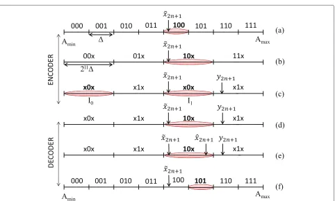
their codewords (Figure 1). With respect to the encoded samples inS1(Figure 2 (a)), removing thel1-LSBs ofx2n+1
is equivalent to quantizing its original continuous value with a uniform quantizer with step size equal to 2l1 (Figure 2 (b)). After removing them1-MSBs, the
result-ing codeword identifies a set of 2m1 disjoint intervals {Ii|i=0,. . ., 2m1−1}, with each interval being of length 2l1(Figure 2 (c)).
At the decoder, a PCM-coded signal is directly recon-structed from its received codeword xˆ2n. This recon-structed value is set to the midpoint of its quantization interval. However, a MPCM-coded signal is decoded by using its codeword xˆ2n+1 and its SI y2n+1. This
pro-cess is divided into two steps: decision and reconstruc-tion. Consequently, in order to decide which Ii interval ˆ
x2n+1belongs to, MPCM decoders exploit the correlation
Figure 1Block diagram of MPCM coding algorithm.
each sample inS1based on previously decoded samples in
S0. This predictiony2n+1acts as SI to decide the interval,
which is obtained by interpolating the previously decoded samples inS0. Therefore, in this decision step, the decoder
uses y2n+1 to select one of the 2m1 disjoint intervals as
shown in (Figure 2 (d)), choosing the closest interval to the prediction. If the decision process is done without error forx2n+1, itsm1-MSBs are properly recovered; otherwise,
the decoder incurs a decision error in which the prob-ability depends on m1 and the accuracy of the SI. The
accuracy of the SI depends on the degree of correlation between the samplesxnand the distortion introduced in the encoding ofS0. Furthermore, the larger them1, the
shorter the minimum distance between the codewords of the same set 2m1, hence, the higher the probability of deci-sion error. As a result, in order to limit these impacts in the encoding algorithm,l0must be lower than or equal to
l1(l0≤l1) andm1must be the minimum possible. Once
the decoder has estimated them1-MSBs ofx2n+1(Figure 2
(d)) in the reconstruction step, it tries to recover itsl1
-LSBs which finally provides an estimated signal xˆ2n+1
(Figure 2 (e)). This reconstruction is done using the quan-tization intervalIi where supposedly liesx2n+1and its SI
(y2n+1) by taking the closest value of the chosen
inter-val to the prediction y2n+1 (Figure 2 (f )). Notably, if the
coding parameters accomplish the following characteris-tics l0 = l1 andm1 = 0, the MPCM encoder/decoder
will act as a PCM coding system, since in such cases, the help provided by the SI does not compensate the loss suffered by encoding each MPCM signal with fewer bits than the PCM signal. In fact, in these cases, midpoint reconstruction performs better than MPCM reconstruc-tion. Nevertheless, in most cases, MPCM performs better than or the same as PCM, with great gains at 1, 2, 3, and 4 bpp.
For a more detailed description of MPCM encoder, the reader is referred to [18,19].
3 Hardware implementation
In order to cope with the high throughput bandwidth of nowadays high-speed cameras, both MPCM encoder and decoder have been implemented over a hardware archi-tecture. The description language used to build its design is VHDL. The proposed hardware implementation has been developed over a Zynq-7000 FPGA of Xilinx fam-ily, specifically over the ZC702 model which includes the XC7Z020-1CLG484CES SoC (System-on-Chip) [20].
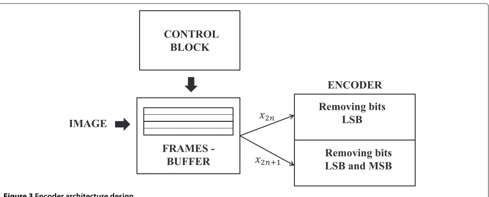
3.1 Encoder architecture
The implemented encoder architecture is illustrated in Figure 3. The original image/frame captured by the cam-era sensors is stored in a memory block whose reading is determined by a control block. In that structure, 16 pixels are read on each cycle so as to speed the encoding pro-cess as much as possible within the scope of the device’s internal memory. This memory acts as an internal buffer of frames to read them in high-speed applications and it is implemented with block RAMs. In this way, we use 52 dual-port 36-Kb block RAMs with ports configured as 512×64 bits, where 64 output bits, namely 8 pixels, are read in each memory output port. These pixels are pro-cessed in the following block, without delay, in the same reading cycle, where they are encoded by removing the correspondingl0orlk andmk bits. Finally, we obtain the coded samples of the image which are sent to the final storage device.
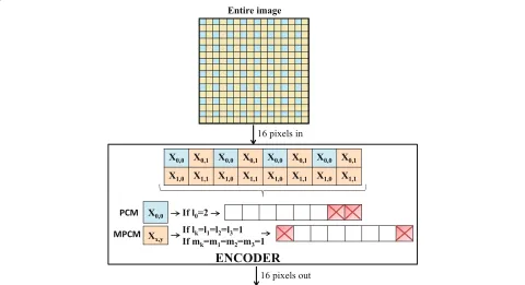
Our proposed implementation design first divides the image/frame intoNset of pixels, where one of the result-ing pixels is encoded usresult-ing PCM and the rest of them with MPCM. We take the strategy of dividing x[n1,n2] into
four (N=4) setsx0,0[n1,n2],x0,1[n1,n2],x1,0[n1,n2], and
x1,1[n1,n2] such that
xp,q[n1,n2]=x
2n1+p, 2n2+q
withpandq ∈ [0, 1] as explained in [19]. Then, the first one is encoded using PCM, removing l0 LSBs, and the
remaining parts using MPCM, removinglkLSBs andmk MSBs. A diagram of the steps used in our hardware algo-rithm is shown in Figure 4. Remark that both the reading and coding of the 16 pixels are performed in the same clock cycle.
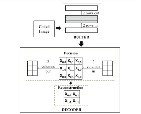
3.2 Decoder architecture
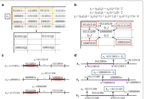
The proposed decoder architecture is shown in Figure 5. In this approach, the buffer is filled with coded samples until the first three lines are completed since at least three rows and three columns of pixels stored are needed (9 pix-els in total) so as to decode a setNof 4 pixels, then the decoding process starts. The decoder is divided into two steps: decision and reconstruction. The recovery of the original image is performed as follows:
1. Three columns of data are processed in decision block, where the PCM signal is reconstructed as shown in Figure 6a. SIs are generated from the previous PCM samples (Figure 6b), and one of the possible intervals2mk is selected in which each
MPCM decoded signal will be placed (Figure 6c).
2. At the decoder reconstruction block, we recover the LSB removed in the encoding process using its SI and the interval corresponding to each MPCM sample as shown in Figure 6d, according to this rule:
ˆ x=
⎧ ⎨ ⎩
a ify<a y ifa≤y≤b b ify>b
.
After completing these steps, we get four decoded pixels.
3. In each cycle, two columns of encoded samples leave the decoder and another two enter into it, keeping the last previous column, considering that it contains the necessary PCM samples to decode the next set of 4 pixels. This process is carried out iteratively until all samples of the three rows from the buffer have been decoded.
4. Then, the buffer is shifted. Two rows leave the buffer and two new ones enter into it, keeping the last previous row, as in case of columns. All the above operations continue until all the input encoded samples are decoded.
The proposed decoder design has been completely pipelined, so this makes each of the aforementioned steps used for decoding to be performed concurrently. In addi-tion, as previously mentioned, four decoded pixels are obtained in each cycle. In this approach, the operating
Figure 4Example of the encoder algorithm withl0=2,lk=1andmk=1.Blue-colored blocks are samples to be coded using PCM and the
Figure 5Decoder architecture design.
frequency has been set to get the 4 pixels, but in order to organize the entire decoded image, a phase-locked-loop (PLL) module has been used, which generates mul-tiple clocks for a given input clock. Therefore in each cycle, 4 pixels are stored in a buffer with a fixed fre-quency, but these pixels are read with a frequency four times higher, thus achieving a serial output without delay. The buffers used in the proposed architecture have been implemented using single dual-port 18-Kb block RAMs.
4 Results
Both encoder and decoder architecture designs have been tested. In this section, we present the performance eval-uation of the complete system in terms of peak signal-to-noise ratio (PSNR), encoding/decoding times, board area usage, maximum frame rate, and speed-ups obtained when compared to a CPU sequential algorithm. The archi-tectures have been synthesized, placed and routed using
Xilinx ISE 14.3 tool, and have been simulated and ver-ified using Matlab/Simulink through System Generator toolbox. They have been designed into the Zynq AP SoC-based board previously mentioned. Occupied board area, maximum frequency, and power consumption estimation have been measured from the Xilinx ISE 14.3 tool. In our experiments, we have assessed the results of eight gray-scale images with 8 bits per sample, five of which (Zelda, Lena, Peppers, Barbara, and Baboon) with a resolution of 512×512 pixels and the rest, a full-HD (1080p) image, a 2, 048×2, 560 image, and a 4K UHD image. Furthermore, we have assigned values to the coding/decoding parame-ters (withN = 4,l1 = l2 = l3, andm1 = m2 = m3)
so as to obtain the best result on average of PSNR for a given bit-rate, although there may be other combinations of parameters that would optimize a particular image as proposed by Marleen Morbee in [19].
a
b
c
d
Figure 6Example of MPCM decoding process withl0=2,l1=1andm1=1.(a)Reconstruction of PCM signals by taking the midpoint of its quantization interval.(b)Obtaining of SI (yk) by interpolating the previously decoded PCM signals.(c)Decision step to recover MPCM signals. Interval selection of the 2m1potential codewords.(d)Reconstruction step to recover MPCM signals.
higher rates (R), which means removing few bits in the encoding process, MPCM algorithm generally provides good PSNR due to the fact that no significant loss occurs in the coding process, and, consequently, no big errors are introduced in the decoding process. Therefore, the
lower the rate (R), the lower the PSNR value. Moreover, as explained in Section 2, in the cases where the chosen parameters meetl0 = l1andm1 = 0, a reconstruction
PCM is applied, so the PSNR corresponding to R = 6
bpp andR = 5 bpp, shown in Table 1, is the same for
Table 1 PSNR values for all tested images for a given bit-rate
PSNR (dB)
R=4 bpp R=4.5 bpp R=5 bpp R=5.5 bpp R=6 bpp Image (l0,l1,m1) (l0,l1,m1) (l0,l1,m1) (l0,l1,m1) (l0,l1,m1)
(1,4,1) (2,4,0) (3,3,0) (1,3,0) (2,2,0)
Zelda (512×512) 39.00 38.90 40.15 41.51 45.04
Lena (512×512) 37.74 37.77 39.82 41.06 44.96
Peppers (512×512) 33.70 36.92 39.32 40.29 44.62
Barbara (512×512) 26.06 35.27 38.91 39.83 44.56
Baboon (512×512) 24.45 33.02 37.61 38.20 43.85
Tractor (1, 920×1, 080) 38.01 39.67 40.22 42.15 44.73
Woman (2, 048×2, 560) 30.53 36.47 39.52 40.70 44.95
Figure 7PSNR as a function of the rate of image tractor coded using MPCM and only PCM.
a PCM coding. One advantage of the proposed MPCM algorithm versus PCM is the possibility of compressing intermediate bit rates (nonintegers) due to the different numbers of bits removed in a set of pixels (l0 = l1). In
addition, MPCM algorithm overcomes in quality to PCM
at high levels of compression . An example of comparison between the MPCM coding and PCM coding is shown in Figure 7 (tractor image), which shows the PSNR values as function of the rate for the image full-HD (1080p). As it can be seen, MPCM obtains the same quality than PCM
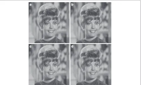
Figure 9A set of four monochromatic images (Tractor1, 920×1, 080) decoded with the following bit rates.(a)Original image. (b)At 6 bpp.(c)At 5 bpp.(d)At 4 bpp.
at low compression rates. However, at high compression rates, MPCM obtains a PSNR improvement up to 15 dB when compared to PCM.
Furthermore, two images compressed at different bit rates by the algorithm MPCM proposed are shown in Figures 8 and 9. As you can see from the pictures, at 6 and 5 bpp, non-perceptual inequality is observed regard-ing the original image. However, some differences begin to be appreciated at a rate of 4 bpp, for example, in the set of images of the tractor, one could see a slight distortion inside the rear wheel at 4 bpp.
4.1 Encoder evaluation
Regarding coding/decoding delay, the proposed encoder architecture works at a maximum clock frequency of 204.96 MHz, that is 4.879 ns. Furthermore, the algorithm requires 16,387 cycles to perform the encoding process for an image resolution of 512× 512 pixels. Therefore, we require 79.952μs to encode any image for the afore-mentioned resolution, which is 12 times faster than the sequential algorithm on an Intel Core 2 CPU at 1.8 GHz with 5 GBytes RAM. As the encoding process does not depend on the internal characteristics of the image, but
Table 2 Area used in the FPGA encoder implementation
Used Available Utilization (%)
Number of slices 14 13,300 1
Number of slice registers (as flip-flops)
17 106,400 1
Number of slice LUTs 35 53,200 1
Number of RAMB36 52 140 37
FMax (MHz) 204.96 -
-Power consumption (mW)
305 -
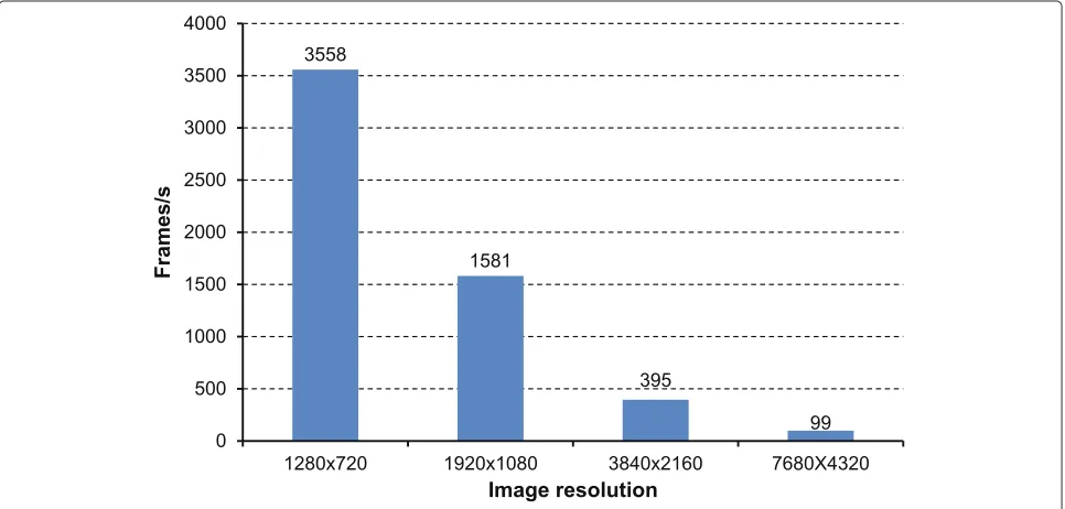
-only on the image resolution, in Figure 10, the maximum frame rate achievable for the proposed architecture is pre-sented. As shown, the hardware implemen tation of the MPCM encoder is able to compress up to 3,558 fps for HD-ready resolution (720p) or up to 1,581 fps for full-HD resolution (1080p).
The high-speed encoding process makes high-speed cameras able to capture continuously and grab without the restrictions of the internal RAM size. For example, the proposed MPCM hardware implementation could compress at 4 bpp rate with a reasonable quality and a throughput bandwidth of 1,640 MBytes/s which will extend the capturing time over the internal camera RAM module up to two times or will permit its transmission over a 40-Gbit Ethernet point-to-point access.
The basic elements of a FPGA are configurable logic blocks (CLBs). CLBs architecture includes 6-input look-up tables (LUTs), memory capability within the LUT and
register, and shift register functionality. The LUTs in the Zynq-7000 AP SoC can be configured as either one 6-input LUT (64-bit ROMs) with one output, or as two 5-input LUTs (32-bit ROMs) with separate outputs but common addresses or logic inputs. Each LUT output can optionally be registered in a flip-flop. Four of such LUTs and their eight flip-flops as well as multiplexers and arith-metic carry logic form a slice, and two slices form a configurable logic block (CLB). Four of the eight flip-flops per slice (one flip-flop per LUT) can optionally be config-ured as latches. Between 25% and 50% of all slices can also use their LUTs as distributed 64-bit RAM or as 32-bit shift registers [20].
Table 2 presents the results of the encoder imple-mentation in terms of hardware resources used, indi-cating the number of used slices, flip-flops, LUTs and 36-KB block RAMs. In addition, it shows an estima-tion of the power consumed using XPower of Xilinx ISE 14.3, being only 305 mW, due to the high segmenta-tion in the encoder design. As shown, only 1% of all the available area in the FPGA is used, so given the large amount of unused area on the FPGA, we could use it to deploy multiple identical encoders that could run concurrently. Thus, different frames could be encoded simultaneously so as to increment the available record-ing time of a high-speed camera. To take advantage of this, we would only have to consider an external mem-ory to support the storage of several frames, considering the blocks RAMs used as intermediate buffers. Another option would be to divide the images or frames in differ-ent collections of lines which could be encoded in parallel.
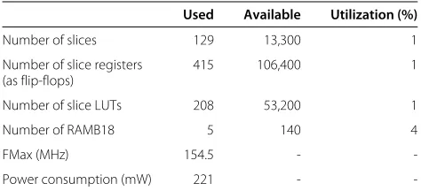
Table 3 Area used in the FPGA decoder implementation for parametersl0=2,l1=1, andm1=1
Used Available Utilization (%)
Number of slices 129 13,300 1
Number of slice registers (as flip-flops)
415 106,400 1
Number of slice LUTs 208 53,200 1
Number of RAMB18 5 140 4
FMax (MHz) 154.5 -
-Power consumption (mW) 221 -
-In this way, a speed-up of 8×fps would be achieved and as a result, the MPCM encoder would be able to com-press up to 12,648 fps for full-HD (1080p) monochromatic resolution.
4.2 Decoder evaluation
As far as the decoder is concerned, the maximum clock frequency obtained for the decoder is 160 MHz with a latency of only 713 cycles. However, the maximum clock frequency has been set at 100 MHz. This frequency is taken as a compromise due to the use of other frequency four times higher provided by the PLL module, as dis-cussed in Section 3.2, since there is a limited frequency for the FPGA used. So, the MPCM decoder is able to recover 400 Mpixels per second at that frequency. On the other hand, the algorithm requires 66,240 cycles to perform the decoding process for an image resolution of 512× 512 pixels, so 662 μs are needed to decode any image for that resolution, being 70 times faster than the sequential decoding algorithm on an Intel Core 2 CPU at 1.8 GHz with 5 GBytes RAM.
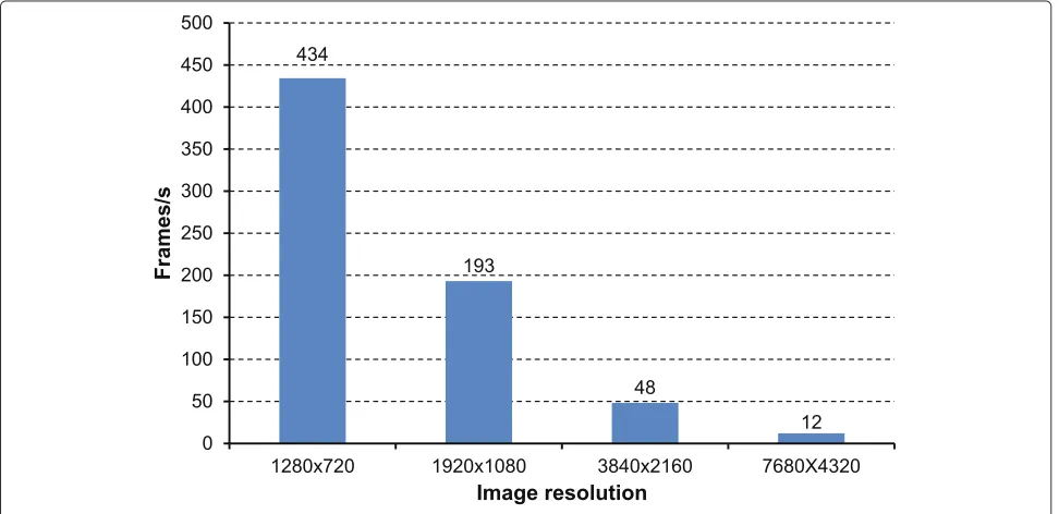
Figure 11 shows the maximum decoding frame rate achievable for the proposed architecture. As shown, the hardware implementation of the MPCM decoder is able to recover up to 434 fps for HD-ready (720p) resolution or up to 193 fps for full-HD (1080p) resolution, which cor-responds to a throughput of 50 MBytes/s, making avail-able to reproduce high-definition cinema at high frame rates.
Regarding the occupied board area, Table 3 shows a summary of the hardware resources required by the decoder, which, in a similar way with the encoder, is less than a 1%. The occupied board area could vary depending on thel0,l1,m1parameters, but in any case it will be lower
than 1%. As indicated in Section 3.2, the buffers used have been modeled on single dual-port 18-Kb block RAMs so as to take advantage of the lower consumption compared to distributed memories, besides being faster. Note that the maximum frequency shown in Table 3 is 154.5 MHz, but in our design, we have set this frequency to 100 MHz as explained previously.
5 Conclusions
In this paper, we have presented an efficient FPGA imple-mentation of the MPCM codec. We have shown the quality of the reconstructed frames in terms of PSNR at different compression rates and for several frames with different textures. Regarding coding speed, the results show that our proposed implementation is able to com-press a full-HD (1080p) resolution picture at 1,581 fps. The maximum achievable throughput bandwidth of our proposed implementation is 409.84 MBytes/s which per-mits the continuous grabbing of a nowadays high-speed camera at an image resolution of HD-ready (1, 280×720p) and a reasonable good quality. But, if the final applica-tion requires a higher image quality, our encoder is able to give up to 1,640 MBytes/s at a 2:1 compression rate, incre-menting the capturing time over the high-speed camera internal RAM memory. The occupied area of the FPGA used is less than 1% of the total available area, which give us the possibility to replicate several times the encoding system and thus, several frames or different collections of lines of the same image can be compressed in a parallel way.
We have also developed in hardware a MPCM decoder module. Our proposed decoder design is able to recover images at 193 fps for full-HD resolution, with an occupied board area of less than 1%.
Competing interests
The authors declare that they have no competing interests.
Acknowledgements
This research was supported by the Spanish Ministry of Education and Science under grant TIN2011-27543-C03-03.
Author details
1Physics and Computer Architecture Department, Miguel Hernández
University, Elche 03202, Spain.2Communications Engineering Department, Miguel Hernández University, Elche 03202, Spain.
Received: 31 January 2013 Accepted: 22 July 2013 Published: 27 August 2013
References
1. Vision Research PHANTOM v641. http://www.visionresearch.com/ Products/High-Speed-Cameras/v641. Accessed 7 January 2013. 2. Fastec Imaging TS3 100-S. http://www.fastecimaging.com/products/
high-speed-cameras/handheld-cameras/ts3-100-s. Accessed 8 January 2013.
3. PHOTRON FASTCAM SA-X. http://www.photron.com/index.php. Accessed 24 January 2013.
4. i-SPEED 3. http://www.olympus-ims.com/es/ispeed-3/. Accessed 7 January 2013.
5. NS Jayant, P Noll,Digital Coding of Waveforms: Principles and Applications to Speech and Video. (Prentice-Hall, Englewood Cliffs, 1984)
6. P Gemeiner, W Ponweiser, P Einramhof, M Vincze. Real-time slam with high-speed CMOS camera, inProceedings of the 14th International Conference on Image Analysis and Processing(IEEE Computer Society Washington, 2007), pp. 297–302
8. O Ismailoglu, I Benderli, M Korkmaz, T Durna, Y Kolak, A Tekmen. A real time image processing subsystem: Gezgin, inProceedings of 16th Annual/USU Conference on Small Satellites,(Logan, Utah, 12–15 August 2002) 9. LH Chen, WL Liu, OTC Chen, RL Ma. A reconfigurable digital signal
processor architecture for high-efficiency MPEG-4 video encoding, inIEEE International Conference on Multimedia and Expo(Swiss Federal Institute of Technology Lausanne, 26–29 August 2002)
10. J Ritter, G Fey, P Molitor. Spiht implemented in a XC4000 device, in Proceedings of IEEE 45th Midwest Symposiumon Circuits and Systems, (Tulsa, Oklahoma, 4–7 August 2002). vol. 1, pp. 239–242
11. I Urriza, JI Artigas, JI Garcia, LA Barragan, D Navarro. VLSI architecture for lossless compression of medical images using discrete wavelet transform, inProceedings of Conference on Design Automation and Test in Europe, (Belfast, 27–29 August 1998), pp. 196–201
12. J Ahmad, M Ebrahim, FPGA based implementation of baseline JPEG decoder. Int. J. Electrical Comput. Sci.9(9), 371–377 (2009) 13. J Rosenthal, JPEG image compression using an FPGA. (PhD Thesis,
University of California, 2006)
14. A Descampe, F Devaux, G Rouvroy, B Macq, JD Legat, An efficient FPGA implementation of a flexible JPEG2000 decoder for digital cinema. (PhD Thesis, Université Catholique de Louvain, 2002)
15. X Chen, L Zeng, Q Zhang, W Shi, A novel parallel JPEG compression system based on FPGA. J. Comput. Inf. Syst.7(3), 697–706 (2011) 16. Y Wang, S Chen, A Bermak. FPGA implementation of image compression
using DPCM and FBAR, inProceedings of IEEE International Symposiumon Integrated Circuits, ISIC ’07,(Singapore, 26–28 September 2007), pp. 329–332
17. D Martinez, MM Van Hulle, Generalized boundary adaptation rule for minimizing rth power law distortion in high resolution quantization. Neural Netw.8(6), 891–900 (1995)
18. J Prades-Nebot, A Roca, E Delp. Modulo-PCM based encoding for high speed video cameras, inProceedings of the 15th IEEE International Conference on Image Processing, ICIP 2008,(San Diego, CA, 12–15 October 2008), pp. 153–156
19. M Morbee, Optimized information processing in resource-constrained vision systems. (PhD Thesis, Universidad Politécnica de Valencia, Universiteit Gent, 2011)
20. Xilinx, Inc., Zynq-7000 all programmable SoC overview, advance product specification - ds190 (v1.2) (Xilinx, Inc., 2012). http://www.xilinx.com/ support/documentation/data_sheets/ds190-Zynq-7000-Overview.pdf. Accessed 20 January 2013.
doi:10.1186/1687-6180-2013-142
Cite this article as:Alcoceret al.:MPCM: a hardware coder for super slow motion video sequences.EURASIP Journal on Advances in Signal Processing 20132013:142.
Submit your manuscript to a
journal and benefi t from:
7Convenient online submission 7Rigorous peer review
7Immediate publication on acceptance 7Open access: articles freely available online 7High visibility within the fi eld
7Retaining the copyright to your article