R E S E A R C H
Open Access
FBMC receiver for multi-user asynchronous
transmission on fragmented spectrum
Jean-Baptiste Doré
*, Vincent Berg, Nicolas Cassiau and Dimitri Kténas
Abstract
Relaxed synchronization and access to fragmented spectrum are considered for future generations of wireless networks. Frequency division multiple access for filter bank multicarrier (FBMC) modulation provides promising performance without strict synchronization requirements contrary to conventional orthogonal frequency division multiplexing (OFDM). The architecture of a FBMC receiver suitable for this scenario is considered. Carrier frequency offset (CFO) compensation is combined with intercarrier interference (ICI) cancellation and performs well under very large frequency offsets. Channel estimation and interpolation had to be adapted and proved effective even for heavily fragmented spectrum usage. Channel equalization can sustain large delay spread. Because all the receiver baseband signal processing functionalities are proposed in the frequency domain, the overall architecture is suitable for multiuser asynchronous transmission on fragmented spectrum.
Keywords: FBMC; FDM; FDMA; Equalization; Synchronization; Channel estimation; Asynchronous processing; Multiuser; Fragmented spectrum; Carrier frequency offset
1 Introduction
The current generation of cellular physical layers such as used by Long Term Evolution (LTE) and LTE Advanced have been optimized to deliver high-bandwidth pipes to wireless users but require strict synchronism and orthog-onality between users within a single cell. The advent of the smart phone and the expected explosion of Machine-Type Communication (MTC) are posing new and unex-pected challenges. Fast dormancy necessary for these types of equipment to save battery power has resulted in significant control signalling growth. Furthermore, as the availability of large amounts of contiguous spec-trum is getting more and more difficult to guarantee, the aggregation of non-contiguous frequency bands has to be considered. Therefore relaxed synchronization and access to fragmented spectrum are key parameters for future generations of wireless networks [1]. This require-ment of spectrum agility has encouraged the study of alternative multicarrier waveforms such as filter bank multicarrier (FBMC) to provide better adjacent channel leakage performance without compromising spectral effi-ciency [2]. frequency division multiple access (FDMA)
*Correspondence: [email protected] CEA Leti, 17 rue des Martyrs, Grenoble 38054, France
has already been considered for FBMC and provides promising performance without strict synchronization [3] between users. However, efficient frequency domain FBMC receiver algorithms have to be considered to fully benefit from the scheme. A first attempt at a practical implementation in the frequency domain for FBMC has been proposed in [4]. Synchronization and channel esti-mation are also based on the use of a training sequence but performance is limited by intercarrier interference (ICI) in the presence of large carrier frequency offset (CFO). This paper presents an architecture of a FBMC receiver suitable for asynchronous multiuser FDMA with very relaxed syn-chronization constraints: timing synsyn-chronization, CFO compensation and channel equalization are addressed.
Correction of CFO has been largely documented for orthogonal frequency division multiplexing (OFDM) [5] and FBMC [6]. A coarse CFO compensation in the time domain is necessary prior to a phase tracking in the fre-quency domain in order to limit ICI. As a different level of frequency offset is associated with each user, these solutions require as many receivers as users and are not suitable for practical implementation. Alternative signal processing methods for CFO compensation in the fre-quency domain should be developed. Iterative ICI can-cellation has been proposed through iterative inversion
techniques [7] or turbo processing [8] but is extremely complex to implement. The authors of [9] proposed an interesting method in the context of an orthogonal fre-quency division multiple access (OFDMA) uplink net-work. This method compensates CFO after fast Fourier transform (FFT) using a circular convolution. A good trade-off between performance and complexity is demon-strated. A low complexity CFO compensation method for FBMC - FDMA based on this method has been investi-gated in this paper.
Channel estimation is a necessary process before demodulation as the radio channel is frequency selective. For multicarrier modulation systems, the estimation is usually performed by sending a training data sequence, called pilot tones, on a set of carriers known to the receiver. The channel is then estimated at the pilot fre-quencies using the classical least squares (LS) or minimum mean-square error (MMSE) estimators [10]. When pilot tones are not available on every carrier, a process of interpolation is required to recover the complete channel response [11]. The interpolation may be done in the time domain [12]. A time-domain channel impulse response is obtained using an inverse Fourier transform of the chan-nel estimated at the pilot frequencies. A filter may then be applied to reduce noise effects and border effects. An interpolated frequency domain channel is then pro-cessed by Fourier transform. Another solution may be to interpolate the channel in the frequency domain. Many algorithms, such as linear interpolation, low-pass filter-ing and spline cubic interpolation have been proposed [13,14]. For most interpolation schemes, the channel is poorly interpolated on the carrier located on the edges of the frequency band. This effect may be neglected when the number of carriers per contiguous frequency band is large but may lead to significant performance degradation of the overall system when the multicarrier modulation is applied to a fragmented spectrum. A robust interpolation scheme for the complete spectrum, including the edges is therefore critical. A solution has already been proposed in [12] using interpolation in the time domain. Performance is increased at the price of higher complexity. Further-more, instability issues are not addressed and may lead to noise enhancement. A stable and robust scheme based on interpolation filters in the frequency domain is proposed in this paper.
Conventional equalization techniques for FBMC are suitable for multiuser reception. Good spectral con-tainment introduced by the matched filter of the receiver helps to avoid distortion from non-synchronous users. Channel equalization may therefore be indepen-dently processed per user. However, if the conventional polyphase network FBMC implementation is employed, then equalization has to be carried out in the time domain. To cope with this issue, frequency-spreading FBMC is
considered [15]: at the cost of a significantly larger FFT (the size of the FFT is multiplied by the overlapping ratio), equalization may be efficiently done using a one-tap com-plex coefficient per subcarrier. A high-performance equal-ization scheme is described in this paper. Performance of the receiver is evaluated and discussed.
The paper is organized as follows: In Section 2, the over-all context for a multiuser asynchronous environment is presented and the benefits FBMC waveforms have in this context are developped. Then in Section 3, the complete architecture of a FBMC receiver adapted to these sce-narios is described and performance results are given. In Section 4, the main features and results are summarized and some perspectives are provided.
2 Asynchronous multiuser context 2.1 FBMC
Single-carrier (SC) FDMA has been chosen for the LTE to provide radio resource access for mobile users to the base station. This uplink multiuser access technique pro-vides flexible resource allocation and is spectrally effi-cient. However, frequency offset between users should be strictly contained and received data signal should be aligned. If these synchronization requirements are not fulfilled, the orthogonality condition is not respected: intercarrier and intersymbol interference dramatically deteriorate performance. In order to guarantee mobility, the base station constantly monitors the time of arrival of received transmission signals. Signaling is sent to the mobile user via the downlink channel in order to syn-chronize this time of arrival at the base station. This constant exchange of control information introduces an overhead on the network that could be significant for asynchronous data communication services such as web access or machine-to-machine communications.
representation that includes only a few adjustable design parameters. The most significant parameter is the dura-tion of the impulse response of the prototype filter also called overlapping factor,K. The impulse response of the prototype filter is given by [16]
h(t)=GP(0)+2
an overlapping factor of K = 4 and N is the number
of carriers. In the following sections, the term carrier
will refer to one of these N carriers and the term sub-carrier will refer to one of the KN frequency domain FFT outputs at the receiver (see Section 3.1). The larger the overlapping factor K, the more localized the signal will be in frequency. In filter bank-based systems, trans-mit pulses are localized in time and in frequency. The orthogonality between carriers is maintained by introduc-ing half a symbol period delay between the in-phase and the quadrature components of every complex symbol. The well-adjusted frequency localization of the prototype fil-ter guarantees that only adjacent carriers infil-terfere with each other. This justifies the use of FBMC waveforms in a non-synchronous context and particularly for the fragmented scenario. Nevertheless, adjacent carriers sig-nificantly overlap with this kind of filtering. In order to keep adjacent carriers orthogonal, real and pure imag-inary values alternate on successive carrier frequencies and on successive transmitted symbols for a given car-rier at the transmitter side. In order to maximize spectral efficiency of the offset QAM (OQAM) modulation, the symbol periodTis halved.
FDMA access schemes have already been considered for FBMC modulations [3], but access on fragmented spec-trum has not been envisaged yet. Fragmented specspec-trum may be viewed as the consequence of relaxed extension of channel aggregation for mobile communications. A user may access more than one frequency band being contigu-ous or not in frequency at any given time. The relaxed
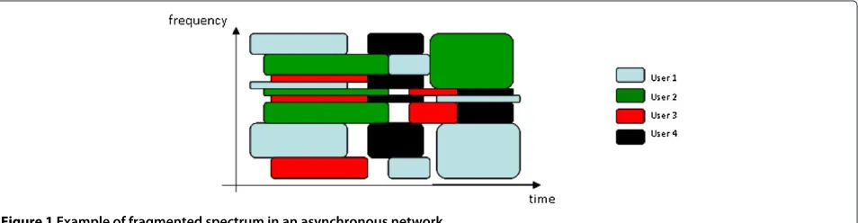
synchronization between multiple users, i.e., users are not strictly synchronized in time, could lead to the generation of a heavily fragmented spectrum both in time and fre-quency. An example of the resulting spectrum is depicted in Figure 1. This phenomenon should be further exac-erbated as messages get shorter as is often the case in machine-to-machine communications.
FBMC-FDMA access schemes appear therefore to be a very promising flexible multicarrier waveform. Efficient implementations of the FBMC-FDMA receivers should thus be considered in such multiuser asynchronous envi-ronments. A solution for this context is investigated in this paper.
2.2 Proposed burst structure
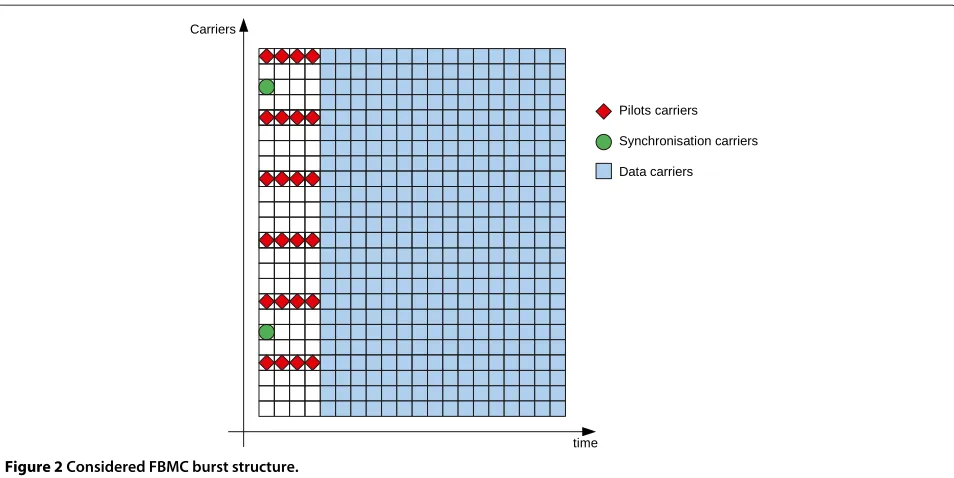
In order to keep a flexible frequency and time block allo-cation, a preamble-based burst approach is considered. Synchronization and channel estimation is performed using the training sequence. Its structure has been defined and is illustrated in Figure 2. It is composed of a pream-ble of durationP-FBMC symbols (Pis set to 4 in Figure 2). The preamble has been designed to accurately detect the start of the burst and gives an estimate of the chan-nel frequency response while preserving the localization properties of the FBMC signal. It is mainly composed of pilot carriers spaced everyDactive carriers for the whole duration of the preamble (Dis set to 4 in Figure 2). The pilot carriers are designed so that the signal transmit-ted on each pilot carrier is constant for the duration of the preamble. Synchronization carriers are added on the first multicarrier symbol but are more sparsely distributed than pilot carriers. These are designed to accurately esti-mate the start of burst. By implementing at the receiver, all the baseband signal processing functions in the frequency domain, the proposed scheme may be extended without loss of generalization to the aforementioned multiuser asynchronous environment.
2.3 Notations
Bold letters denote vectors and matrices. Upper-case and lower-case letters denote frequency domain and time
Figure 2Considered FBMC burst structure.
domain variables, respectively. The following notations are used:
• (.)tTranspose
• (.)HHermitian transform
• E[ . ]Expectation operator
• tr[ . ]Trace operator
• ||.||l -norm
Fstands for theN×N-DFT (discrete Fourier transform) matrix defined as:
F= √1
N
⎡ ⎢ ⎢ ⎢ ⎣
1 1 1 . . . 1
1 wN w2N . . . wNN−1 ..
. ... ... ...
1 wNN−1 wN2(N−1) . . . wN(N−1)(N−1)
⎤ ⎥ ⎥ ⎥ ⎦ (2)
wherewN =ej 2π
N. Matlab notation was used to index the
matrix. Therefore,A = B(:, 1 : U)means thatAis built with the firstUcolumns and all the rows ofB.
3 Receiver architecture 3.1 Overview
A flexible architecture for multiuser asynchronous recep-tion on fragmented spectrum is able to exploit the advan-tages of FBMC if the signal is efficiently demodulated
in the frequency domain without a priori knowledge
of the FFT timing alignment (i.e. the location of the FFT block, this property is called asynchronous FFT). A receiver architecture based on this assumption is depicted in Figure 3. An asynchronous FFT of sizeKNis processed every block ofN/2 samples generatingKNpoints, i.e. ifrm is themth received vector, aKN-point FFT is computed
for samplesk=(n+m×N/2)withn=0, 1,. . .,NK−1. These successiveKNpoints are stored in a memory unit.
The detection of a start of burst is then achieved on the frequency domain (i.e. at the output of the FFT) using a priori information from the preamble. CFO is first estimated using the pilot subcarrier information of the preamble by computing the phase of the product between two consecutive FBMC symbols at the location of the pilot subcarriers. The propagation channel is assumed static for the duration of the burst. As described in [17], when large CFO correction is required, a first step in the estimation process consists of scanning the subcarriers around the pilot subcarrier locations to determine the subcarrier with the highest energy. A tracking algorithm of the CFO may complete the synchronization process when the duration of the burst is large and the accuracy of the preamble-based detection algorithm does not meet the required level [18]. CFO compensation is then performed in the frequency domain using a feed-forward approach.
The channel coefficients may be estimated on the pilot subcarriers of the preamble. Authors of [6,19] have already considered a similar approach by introducing a phase term to correct the CFO. In Section 3.2, this technique is completed by an efficient algorithm that compensates inter-carrier interference. The channel is then estimated on the pilot subcarriers before being interpolated on every
active subcarrier. The use of a KN-point FFT makes
the interpolation particularly specific to this receiver and a description of the proposed algorithm is detailed in Section 3.3.
Figure 3Block diagram of the proposed receiver.
before filtering by the FBMC prototype filter (Section 3.4). Demapping and log-likelihood ratio (LLR) computation complete the inner receiver architecture. A soft-input for-ward error correction (FEC) decoder recovers finally the original message.
The asynchronous frequency domain processing of the receiver combined with the high stop-band attenuation of the FBMC prototype filter provides a receiver archi-tecture that allows for multiuser asynchronous reception. FFT and Memory Unit are common modules, while the remaining of the receiver should be duplicated as many times as the number of parallel asynchronous users the system may tolerate.
3.2 Carrier frequency offset compensation
3.2.1 Problem formulation
When the received symbolrCFO
m is affected by CFO, the
signalrCFOm can be written as
rCFOm = i
dirimej(2π δim+i)+zm (3)
whererCFOm ∈CKN×1is the received time domain vector, rim ∈ CKN×1 is the time domain vector associated with useri,δiis the CFO for userirelative to the carrier spacing (assumingNcarriers),iis a random phase for useriand zm is the noise vectordi ∈ CKN×KN a diagonal matrix defined for useriby
di[k,k]=ej2πkδ
i
N (4)
The considered scenario is an uplink asynchronous access with multiple different CFOs. Since CFOs associated with different users are different, correction must be per-formed separately for each user. The correction of the CFO for one given user cannot then be realized in the time domain with reasonable complexity as described by the authors of [9]. For this reason, we propose a frequency domain processing. Thanks to the very good frequency localization of the FBMC carriers, the asynchronous time reception of users does not cause any frequency interfer-ence between users (providing a frequency guard band of only one carrier). Thus, after FFT, the correction of the CFO in the frequency domain is described without loss of generality for one user. In the following, subscript indexi
is dropped. AfterKNfast Fourier transform, (3) becomes
ˆ
Rm=CRmej(2π δm+)+Zm (5) whereZm ∈ CKN×1is the additive white Gaussian noise vector andC∈CKN×KNis a Toeplitz matrix defined by
C=FdFH (6)
The coefficients of C measure the level of intercarrier interference (ICI) and may be written as
C[i,k]= sinc(Kδ−(i−k)) sincKδ−N(i−k)
e−jπ(N−1)(KNδ−(i−k)) (7)
may then be decomposed into its integer and its fractional Assumingqis known, the required range of detection for δ may be very small. For instance, in the case of FBMC with a prototype filter of durationK = 4, the maximum level of ICI is introduced when =12.5%.
3.2.2 Proposed correction scheme
As described in the previous section, CFO may be decom-posed into integer and fractional parts. The integer part is easily corrected by a shift ofq subcarriers at the out-put of theKN-point FFT. The phase term should then be compensated by a phase correction factor. A simple and efficient way to reduce ICI introduced by the factional part of the CFO,, may be achieved by complex filtering of the received sequence. In order to derive the complex coefficients of filterWthat mitigates ICI, two criteria are considered:
• Zero-forcing criterion (): using Equation 5, and omitting the phase term, which has been corrected, we defineW such as:
WC=I (9)
By substitutingCwith the expression in (6), (9) may be rewritten as
WFdFH =I (10)
AsFFH =FHF=IandddH =I, the filterWmay be
derived by
W=FdHFH (11)
• Minimum mean square error criterion (): the filter may also be optimized to minimize the mean square error (MSE), taking the noise level at the receiver into account:
West=arg minWWRˆm−Rm 2
(12)
By taking the derivative of the expectation of the trace, the minimization problem becomes:
∂
In the presence of the additive white Gaussian noise (AWGN),EZmZmH
can be expressed by:
W= σ
For both cases, the matrixWis Toeplitz and is there-fore characterized by only KN complex coefficients. In general, R is not a diagonal matrix but rather a band diagonal matrix and depends on the considered FBMC prototype filter. A closed-form expression ofW may be obtained if and only ifR is invertible. However,Wmay be derived by a non-linear optimization process or by a using a pseudo-inverse based for instance on singular value decomposition.
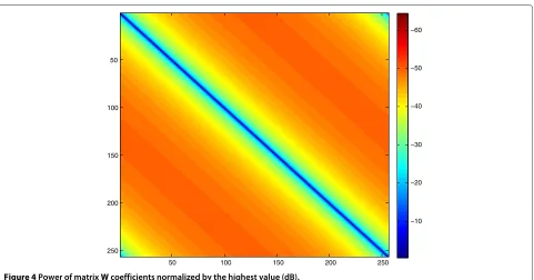
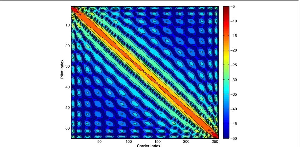
The correction of the fractional part of the CFO with either or filters requires aKNcomplex-tap filter. Never-theless the complexity may be significantly reduced as ICI introduced by the CFO rapidly decreases with the index of the interfering subcarriers (since || < 1/(2K)). In Figure 4, the power of theWcoefficients for a 256-point FFT and a CFO of 10% is plotted. In that example, almost all the power is located around the diagonal. We proposed to approximate matrixWby a sparse band Toeplitz matrix
with 2Q+1 terms on each column and centred on the
diagonal. This is done by forcing all the other coefficients to 0. A trade-off between complexity and accuracy of the frequency offset correction should be found for parame-terQ. The 2Q+1 coefficients may be extracted fromW through equation (11) or (15).
3.2.3 Performance and practical implementation of the CFO correction algorithm
The performance of the proposed algorithm is analysed and a practical implementation is derived in this section
using the following FBMC parameters: N = 1, 024 and
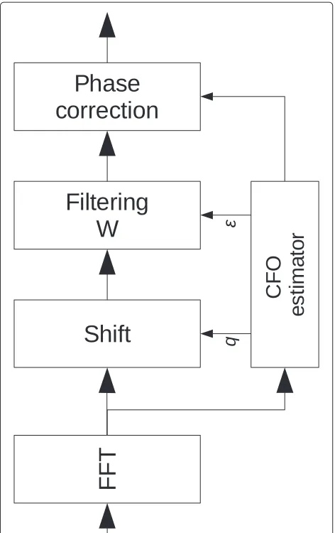
K = 4. Figure 5 gives the architecture of the proposed implementation. The first step, performed by the Shift module, consists in correcting the integer part q. The result is then filtered by the 2Q+1-tap filterW. A phase correction performed on each FBMC symbol completes the CFO correction process.
The relative mean square error (RMSE) for δ values
from 1% to 12% and for different values ofQis given in Figure 6. RMSE has been defined by
RMSE=10 log10
RMSE is a measure of the signal to interference level as seen on the constellation. In the example, a QPSK
mod-ulation has been considered and RMSE decreases as Q
50 100 150 200 250 50
100
150
200
250
−10 −20 −30 −40 −50 −60
Figure 4Power of matrixWcoefficients normalized by the highest value (dB).
WhenQ=0, the algorithm only performs phase correc-tion. The benefit of ICI mitigation is clearly demonstrated. ParameterQcould be chosen as a function of the system signal-to-noise ratio (SNR) so as to limit the system by thermal noise but not by interference.
In practice, the estimation of the CFO is never perfect. As illustrated in Figure 6, a residual CFO of 1% gener-ated by the correction mismatch exhibits a RMSE power
level below−30 dB and does not degrade performance
significantly. This result is interesting to note for practi-cal implementations. Indeed, the determination of matrix
W requires complex computation (matrix inversion or
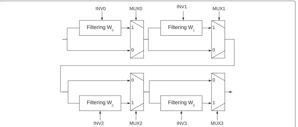
non-linear optimization). Therefore, a possible practical implementation is to pre-compute a set of filters and use a combination of them. Figure 7 depicts the implemented filtering architecture based on a cascade ofP = 4 pre-computed filters. Using theMUXcommand, it is possible to apply or bypass the filter correction. When a negative
CFO correction should be applied, theINVcommand is
activated. As filters for negative CFO are derived from fil-ters for positive CFO through a simple permutation and complex conjugation of its coefficients, the operation is performed with little complexity.
For instance,Wi can be optimized for an incremental drift of 1% by
δi=2i×1%, i=0. . .P−1 (17)
In case ofQ = 3 andP = 4, 28 complex coefficients
must be stored. A correction range of [−15%; 15%] is then possible. As an example, a CFO of 11.7% is corrected by
settingMUX0= 1,MUX1= 1,MUX2= 0 andMUX3= 1.
The effective CFO corrected is 1%+2%+8%=11%.
The RMSE performance of the proposed scheme is illus-trated in Figure 8. We consideredP=4 filters withQ=3 and using the optimization process of (17) and perfect phase estimation. A step shape of the curve is observed and comes from the finite resolution of the compensa-tion (i.e. a step of δ = 1%). When δ > 12.5% a shift ofp = 1 subcarrier is performed. These results demon-strate the trade-off between performance and complexity of the algorithm combined with the proposed cascade filters architecture.
A technique to mitigate ICI generated by CFO has been introduced in this section. All the operations have been carried out in the frequency domain and the scheme has given satisfactory performance results while being adapted for implementation.
3.3 Channel estimation and interpolation
Another important function that should be performed in the frequency domain is to recover the channel coef-ficients on each active subcarrier. This operation is achieved after the channel coefficients have been esti-mated on the pilot subcarrier location.
3.3.1 Problem formulation
Figure 5Block diagram of the proposed CFO correction scheme.
the duration of the OFDM symbol, a frequency-selective wideband channel converts to a number of subcarrier channel with flat fading. For FBMC, Hirosaki [20] showed that this property may be preserved if the equalizer at each subcarrier channel is fractionally spaced.
Therefore, under these assumptions, the received vector Rmay be written after Fourier transform as
R=diag(H)X+Z (18)
where diag(H)is aNH×NHdiagonal matrix of the chan-nel frequency response,XtheNH ×1 vector of symbols to transmit and Zthe NH × 1 vector of additive white Gaussian noise.NHis the number of active subcarriers.
We labelledUP, the indices of the pilots (located at the central location, as aKN-point FFT is considered at the front end of the receiver) andUH, the indices of the active subcarriers.Npis the number of pilot subcarriers. The LS
channel estimation ofP, the pilot vector, at indicesUPis given by [10]
Accurate estimation, Hˆ, of the channel coefficients H may be derived from the observation ofPˆ using an inter-polation filterWof sizeNH×Np.
ˆ
H=WPˆ (20)
To construct the filter W, the following minimization problem should be solved:
West=arg min
Then, sincePˆ is a least square estimate ofP, the follow-ing equation may be written:
ˆ
Then, if his the N × 1 vector of the channel impulse
response,HandPmay be expressed as
P=F(UP, :)h=FUPh (25)
H=F(UH, :)h=FUHh (26)
Finally (22) may be rewritten as
= trWFUPhFUP
where h is the time domain channel autocorrelation
matrix of sizeN×NandσZP2 the noise power. By taking the partial derivative ofwith respect toWand making it equal to zero, (27) becomes
Figure 6RMSE performance of the proposed filtering scheme.Wis derived using the truncated method.
whereIis the identity matrix of sizeNp×Np. In many cases, the matrix is ill-conditioned and impossible to invert. However, a pseudo-inverse using a singular value
decomposition (SVD) may be computed to deriveW, but
this method may lead to an unstable result. The power dis-tribution of matrixWcoefficients is given in Figure 9 for a channel distribution with a square delay profile in the time domain (NH =256 andNp=64).
In this example, the power distribution of matrix W
coefficients is mainly located around the diagonal. It
should be noted that the coefficients located at the cen-ter of the matrix have very similar values. On the con-trary, at the edges of the matrix, the coefficients are significantly different. This property has been exploited to construct a new optimization criterion. The
cri-terion imposes complexity constraints on matrix W
coefficients as a function of their location within the matrix.
From a practical point of view, implementing a com-plex filter with a large set of comcom-plex coefficients may
Figure 8RMSE of the proposed filtering approach based on a cascade ofP=4 pre-computed filters withQ=3.
be extremely costly. The overall complexity should often be kept under control in order to fit implementation area constraints. The following constraints have thus been added to the minimization problem:
• Wis a matrix with realQ coefficients per row instead of complexNpcoefficients per row
• The pilot carrier distribution follows a regular pattern, i.e. the sampling of the channel is uniforma • At leastQ pilots are active per set of contiguous
subcarriers
The structure of matrix W is divided into three sub-filter blocks, a left sub-sub-filter block, a middle sub-sub-filter
Carrier index
Pilot index
10
20
30
40
50
60
50 100 150 200 250 −50
−45 −40 −35 −30 −25 −20 −15 −10 −5
block and a right sub-filter block, so that matrixWmay
whereWlis theNl×Qmatrix representing the left sub-filter block,Wmis the Nm ×Qmatrix representing the
middle sub-filter block and Wr is the Nr × Q matrix
representing the right sub-filter block.
The minimization problem of (27) may then be decom-posed into three constraint minimization problems
func-tion of the three sub-filter blocks Wl, Wm and Wr.
Further constraints on the coefficients may be added on the minimization algorithm to guarantee stability. This optimization process may be computationally demand-ing but allows for a control of the complexity of the implemented interpolation process.
FiltersWl,WmandWrare obtained through the follow-ing minimization problem by usfollow-inga prioriknowledge of
andσZ2:
By applying (27) into (30), the minimization may be realized considering an a prioriknowledge of the auto-correlation matrix of the time domain channel impulse
response. By applying this constraint, the level of imple-mentation complexity may be traded off against the target performance of the channel estimation module.
The optimization process is not necessarily imple-mented on the real time system. A stable and efficient interpolation scheme adapted to the channel conditions is provided while complexity is kept under control.
3.3.2 Application to the proposed preamble structure
The estimation of the channel coefficients is performed before applying the FBMC prototype filtering. The LS estimates of the channel coefficients are computed by applying a CFO phase correction on the received signal according to the location of the pilot symbol on the pro-totype filter. Performance may be further improved by considering all the positions of the prototype filter and by applying a maximum ratio combining algorithm after interpolation.
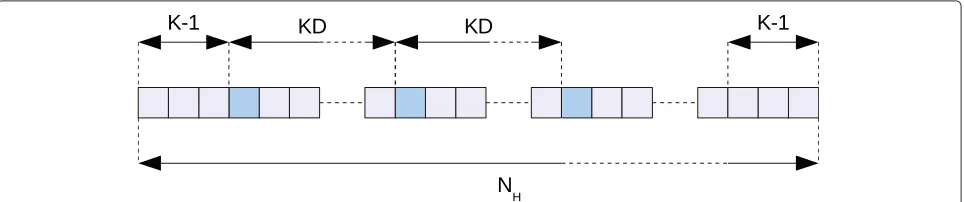
Therefore, by considering LS estimates at the center of the FBMC prototype filter, the structure of the pilot pat-tern is depicted in Figure 10. A pilot subcarrier is located everyKDactive subcarriers. The first pilot is located on subcarrierK−1. No pilot subcarrier is active on the right edge of the spectrum, thereforeK−1+Dchannel coeffi-cients should be derived. The number of active subcarriers is equal to NH = 2(K − 1)+ NpKD, whereNp is the number of active pilots.
Under these assumptions, and consideringQis even,Nr,
NmandNlmay be expressed as follows:
Nl = K−1+KDQ2 −
The channel taps are assumed to be uncorrelated and as a consequencehis a diagonal matrix. The most difficult task of the problem formulation consists in defining the a priori time domain channel autocorrelation delay pro-file. Different profiles may be considered and Figure 11 gives examples of possible distributions. For instance, an
a prioriautocorrelationh profile adapted to single fre-quency network is characterized by a 0-dB echo channel
Figure 11Examples of considered autocorrelation channel delay profiles.(a)Rectangle,(b)low decay,(c)exponential decay(d), 0-dB echo.
and is given in Figure 11d. The most conservative shape, the rectangular distribution (see Figure 11a), has been considered in the following section of the paper.
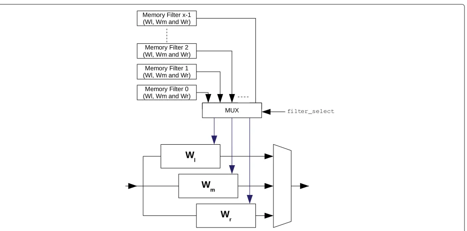
The optimization process is computationally intensive, making it difficult for a real time implementation. In order to maximize the interpolation performance while main-taining a reasonable level of complexity, the interpolation architecture depicted in Figure 12 has been considered. A
set ofxfilters is optimized according to a target SNR, time domain channel duration, time domain profile, etc. The choice of the filter to apply is controlled by an entity that estimates the received channel conditions and decides which filter is the most suitable to the channel condi-tions measured at the receiver. Estimated pilot subcarriers are fed through the three filter blocks and generate three interpolated channel estimates. The choice of the channel
estimate is controlled by a multiplexer according to the subcarrier index.
3.3.3 Performance results
The following parameters have been taken for a numerical evaluation:
• K =4 • D=4
• N =1, 024
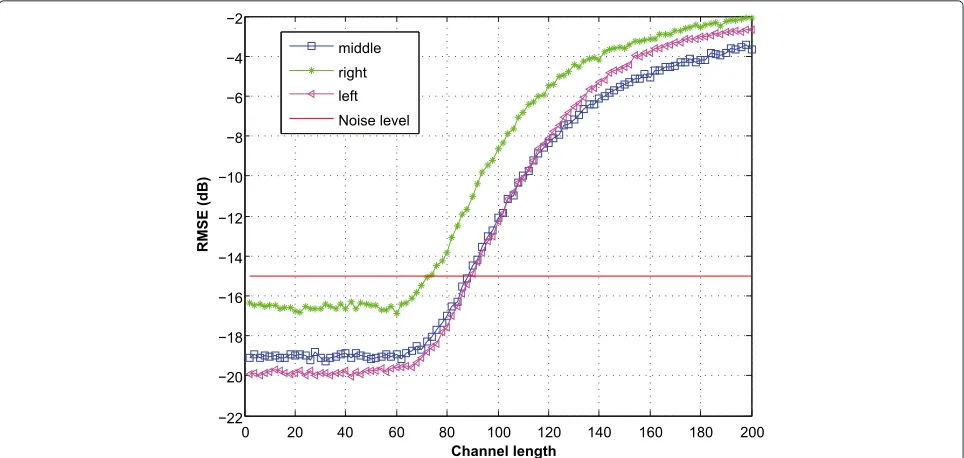
The RMSE of the channel frequency response versus the channel delay spread expressed in number of time domain samplesb for a SNR of 15 dB is given in Figure 13. The RMSE is defined by
RMSE=10 log10
E
WPˆ−H2
E||H||2 (dB) (32)
Filters have been first optimized for Q = 10, a channel duration of 64 samples and a SNR of 15 dB. The perfor-mance is estimated using a Monte Carlo simulation based on the draw of 1, 000 randomly generated channels with rectangular time profiles.
The RMSE is below the noise level for the three filter blocks. However, only a marginal gain is achieved for the right filter block. This is explained by the pattern consid-ered in the pilot scheme; on the right edge,KD+K−1 channel coefficients have to be interpolated while no pilot subcarriers are located at the edge.
From a practical point of view, it is interesting to deter-mine the number of coefficients required depending on the channel delay spread. In Figure 14, the variation of RMSE versus channel delay spread for filter block designed for a channel delay spread length of 64 time
domain samples, SNR= 15 dB and for various
interpo-lation lengthQis given. When filter interpolation length
Qis increased, performance improves. Right filter blocks designed withQ=4 andQ=6 exhibit poor performance due to the channel delay spread. On the other hand, for left filter blocks, the variation on performance is much smaller and less than 1 dB between the caseQ = 4 and the case
Q= 10. Increasing interpolation lengthQalso increases the number of coefficients to store. This number of coef-ficient exhibits polynomial complexity inO(Q2)making large numbers ofQcostly for implementation.
The influence of the SNR on the channel estimation is given in Figure 15. Three filter blocks have been designed for a channel delay spread length of 16 time domain sam-ples and SNR values of 15, 25 and 60 dB. The distance between the thermal noise and RMSE is given as a func-tion of the SNR. For low SNR of 0 dB, a gain of 5 dB is given by a filter block optimized for a SNR of 15 dB. As the noise level is increased, the filter blocks optimized for a SNR of 25 dB become more optimal up to around 36 dB, when the filter blocks optimized for 60 dB become more appro-priate. These results showed the importance of using filter blocks with key characteristics designed around the actual working SNR in order to maximize channel estimation performance.
0 20 40 60 80 100 120 −22
−20 −18 −16 −14 −12 −10 −8 −6 −4
Channel length
RMSE (dB)
Q=4 Q=6 Q=8 Q=10
Figure 14RMSE versus channel delay spread for a SNR of 15 dB for various interpolation filter lengthsQfrom 4 to 10.Channel length in the figure stands for the channel delay spread expressed in number of time domain samples.
To conclude this section, a set of filter blocks for a chan-nel delay spread lengths of 16, 32 and 64 time domain
samples at a SNR= 15 dB and with Q = 8 has been
optimized. The RMSE across the active subcarrier band (this includes the left and right edges) as a function of the channel delay spread for a fragment of 262 active sub-carriers has been plotted in Figure 16. When the channel
delay spread is short, the use of an adequate filter block improves the RMSE of the interpolated channel. This figure illustrates the gain offered by the filtering approach if the channel delay spread is known and/or estimated. A comparison between an interpolation structure based on the state of the art and the proposed filter block structure adapted to the edges of the active spectrum is also given.
Figure 16RMSE as a function of the channel delay spread for a SNR of 15 dB and for different interpolation filter blocks.Channel length in the figure stands for the channel delay spread expressed in number of time domain samples.
The proposed method gives a performance improve-ment of up to 7 dB on the RMSE of the estimated channel. Interpolation errors at the edge of the fragment dominate the RMSE. For large frequency fragment the gain becomes negligible. Performance improvement is mainly due to the small number of pilot subcarriers located in the frequency fragment making the proposed approach particularly adapted to multiuser asynchronous fragmented spectrum usage.
3.4 Inner receiver architecture
3.4.1 Proposed architecture
The proposed equalizer is placed directly after the FFT and before the FBMC prototype filtering. This strategy is suited for asynchronous processing of multiusers in the frequency domain using a shared FFT processor. Assum-ing the channel delay spread, L, small compared to the
KN-point FFT, the symbols at the output of the FFT may be written as follows:
R(k,p)=H(k)X(k,p)+Z(k,p)+ZI(k,p) (33)
wherekis the subcarrier index,pthe index of the FBMC symbol,H(k) the complex channel coefficients for sub-carrier k, Z(k,p) the AWGN sample and ZI(k,p) the inter-symbol interference (ISI) contribution. The chan-nel here is again assumed static for the duration of the burst. When the matrix is diagonal, the ISI term can
be omitted. This assumption is a good approximation when the delay spread of the channel is small com-pared to the size of the FFT. To illustrate the validity of this assumption, we depicted in Figure 17 the power of the channel matrix coefficients in decibels for a chan-nel delay spread size ofKN/64 andKN/16 time domain samples (KNis set to 512). An average over 1, 000 chan-nel realizations was done, each tap following a Rayleigh process.
When the channel is short, the power is located on the diagonal term validating the proposed assump-tion. When the channel is longer, power spreads over the diagonal term of the matrix, and as a result, per-formance of the one-tap equalizer starts showing its limitations.
The goal of the equalizer is to recoverX(k,p)from the observationR(k,p)and the estimated channel coefficient
H(k). The ZF or MMSE criteria are classically used and may be expressed as follows:
ˆ
X(k,p)= H ∗(k)
Q(k) R(k,p) (34)
whereQ(k)is the optimized factor according to the ZF or MMSE criterion:
QZF(k)= |H(k)|2 (35)
QMMSE(k)= |H(k)|2+
σZ2(k)
Figure 17Average power of the channel matrix coefficients for different channel delay spread.
whereσX2(k)is the expectation of the power ofXon sub-carrierkandσZ2is the expectation of the power ofZon subcarrierk. For the following, noise power is assumed to be constant over all the subcarriers.
Once the signal is equalized, the samples are filtered by the FBMC prototype filter before down-sampling by a fac-torK. After payload extraction, OQAM inverse transform, LLR values are obtained. The LLR is defined as
LLR(b(m,n))=log
Pb(m)=1| ˆY(n)
Pb(m)=0| ˆY(n)
=log
α∈0 nP
Yn=α| ˆY(n)
α∈1 nP
Yn=α| ˆY(n)
where 0n (resp. 1n) is the set of symbols comprising a bit 0 (resp. 1) for bitn,Yˆ(n)is thenth real symbol after filtering and inverse OQAM transform andb(m,n)is the
mth bit mapped to thenth symbol.Yˆ(n)is written as ˆ
Y(n)=(n)Y(n)+ZY(n) (38)
where(n) is a factor depending on the criterion of the equalizer andZY(n)is the noise associated with symboln of varianceσZY2
where G(p) is the pth prototype filter coefficient expressed in the frequency domain,σZY2 the noise variance andSn(p)is a set of subcarrier indices. We group into this set the indices of subcarriers used for the computation of symboln.(n)may be expressed by
We assumed that the conditional pdf ofYˆ(n)is Gaussian and is expressed by
P
By applying Bayes rules, assuming equal distribution of symbols and using the max log approximation
logiβi=maxilogβi
, equation (37) may be rewritten as
Further, complexity simplification of (42) may be consid-ered with negligible performance loss such as the tech-niques described in [21].
3.4.2 Simulations results
The proposed equalization scheme has been evaluated by simulation using the parameters derived from the LTE mode 10-MHz parameters and can be found in Table 1.
First, the effects of timing offset (i.e. location of the FFT) on the proposed equalizer has been simulated. The MSE of a QPSK constellation with ZF equalization has been
Table 1 Simulated system parameters
Parameter Value
Active carriers 601 (9 MHz)
Type QPSK
estimated using the proposed equalization technique for various time offset of the KN-point FFT location. The following channel has thus been considered:
hk(t)=δ
where parameterkis the timing offset introduced by the FFT processor. An interpolation filter optimized for a SNR of 15 dB and a delay spread of 32×1/Fewas considered for channel estimation. The simulation results are depicted in Figure 18.
The MSE on the constellation depends on the timing offset. The worst-case MSE is found whenk is equal to
N/4; in this case, the receiver is affected the most by the interference from the previous or next multicarrier sym-bols. The best case comes as expected when the FFT is perfectly aligned, i.e. timing offset is close top×N/2 ∀p. This confirms that the proposed frequency domain equal-izer scheme combined with channel estimation does not require FFT synchronization and is therefore adapted to asynchronous multiuser reception.
The combined performance of the proposed receiver algorithm is then evaluated. A working SNR of 5 dB has been considered and the bit error rate (BER) after Viterbi decoding for various channel delay spread lengthLof time domain samples has been measured. The channel impulse response has been defined as
Figure 18Effects of the timing offset on the RMSE on a QPSK modulation.kis the timing offset.
where L is the number of taps in the channel impulse
response and αi are complex coefficients following a
Rayleigh distribution. With these assumptions, the delay spread of the channel is equal toL/Fe. The resulting BER at the output of the receiver has been evaluated and aver-aged for 10, 000 channel realizations. Figure 19 gives the
simulated performance of the receiver for various channel interpolation filters as a function of the channel delay spread.
The performance obtained with the interpolation fil-ter optimized for a channel delay spread length of
N/(4Fe) time domain samples is of particular interest as
Figure 19Performance of the proposed receiver for various interpolation filters as a function of channel delay spread.Interpolation filters were optimized for a SNR of 15 dB and a channel delay spread of respectivelyN/ (32Fe), 9N/ (128Fe),N/ (8Fe)andN/ (4Fe). Equivalent CP durations
it demonstrated the limitations of the proposed scheme. When the delay spread of the channel is greater than 0.15 × N/Fe, performance is limited by the proposed equalization scheme rather than the channel estimation processing as the one-tap equalizer becomes inefficient. On the other hand, for channel delay spread below 0.15×N/Fe, one-tap equalization is sufficient and channel estimation performs beyond requirement when an appro-priate interpolation filter is considered. These results compare with the performance of an OFDM receiver with a guard interval length of at least 1/8×N. In Figure 19, the guard interval length for an equivalent OFDM system with a FFT size ofNis given. Performance of the receiver may be further improved by considering multi-tap equal-ization.
The choice of the interpolation filter also impacted on performance. When a filter optimized for a channel exhibiting a large delay spread is applied to a channel with a short delay spread, a significant amount of noise is not filtered. Performance is then better if the interpolation filter is adapted to the actual channel delay spread.
The proposed frequency domain receiver architecture seems very attractive for asynchronous multiuser cessing. Fair performance has been obtained by the pro-posed equalizer scheme; the receiver is robust for large delay spread environment. As a comparison, the normal LTE guard interval is set to 4.69Aμs or approximately 1/14×N.
4 Conclusion
This paper presented a novel architecture and algorithms for FBMC reception. All the baseband signal processing functions are implemented in the frequency domain and no strict synchronization requirement on the FFT, the first element of the receiver, is required. This asynchronous frequency domain processing of the receiver combined with the high stop-band attenuation of the FBMC proto-type filter provides a receiver architecture that allows for multiuser asynchronous reception.
Particular attention has been paid to CFO compensa-tion in order to relax synchronism requirements beyond one carrier spacing. An algorithm to mitigate ICI has been proposed and simulated. The performance of a prac-tical reduced complexity implementation is simulated. Depending on the receiver target SNR, complexity may be traded off to keep RMSE introduced by CFO below ther-mal noise. Channel interpolation has also been carefully considered. As multiuser asynchronous FDMA generates heavily fragmented spectrum blocks, channel estimation should be optimized for the edges of the receiver active carrier bands. A performance improvement of up to 7 dB on the RMSE of the estimated channel may result on some simulated scenarios. Finally, a new equalizer scheme has been thoroughly presented. Its complexity is contained
while good performance for channel exhibiting large delay spread is achieved. As a comparison, using the 10-MHz LTE parameters, the receiver performs well for channels with delay spread of up to 8.3μs. This compares with standard LTE that has been designed for channels with delay spread of up to 4.7μs. Moreover, we have demon-strated that the proposed equalizer does not require FFT synchronization and is therefore adapted to asynchronous multiuser reception.
Further work should consider implementation perfor-mance and complexity estimation with a comparison to similar flexible systems using traditional OFDM tech-niques. Eventual cost overhead of FBMC implementation and finite precision effects in this context would further complete the study. At the system level, radio resource simulations are necessary to understand the benefits of the multiuser asynchronous approach. Its potential gains in system capacity and energy consumption compared to already existing solutions could be evaluated.
Endnotes
aThe proposed method also applies to non-uniform
sampling, but the problem is more complex to formulate. bChannel delay spread is the time delay between the
arrival of the first received signal component and the last received signal component associated with a single transmitted pulse.
Competing interests
The authors declare that they have no competing interests.
Acknowledgements
The research leading to these results has received funding from the European Commission’s seventh framework program FP7 ICT Call8 under grant agreement 318555 also referred to as 5GNOW.
Received: 30 November 2013 Accepted: 13 March 2014 Published: 28 March 2014
References
1. G Wunder, M Kasparick, S ten Brink, F Schaich, T Wild, I Gaspar, E Ohlmer, S Krone, N Michailow, A Navarro, G Fettweis, D Ktenas, V Berg, M Dryjanski, S Pietrzyk, B Eged, 5GNOW: Challenging the LTE design paradigms of orthogonality and synchronicity, inIEEE 77th Vehicular Technology Conference (VTC Spring), 2013(IEEE, Piscataway, NJ, 2013) 2. D Noguet, M Gautier, V Berg, Advances in opportunistic radio
technologies for TVWS. EURASIP J. Wirel. Commun. Netw.2011(1), 170 (2011)
3. Y Medjahdi, M Terre, D Le Ruyet, D Roviras, A Dziri, Performance analysis in the downlink of asynchronous OFDM/FBMC based multi-cellular networks. IEEE Trans. Wireless Commun.10(8), 2630–2639 (2011) 4. TH Stitz, T Ihalainen, M Renfors, Practical issues in frequency domain
synchronization for filter bank based multicarrier transmission, in3rd International Symposium on Communications, Control and Signal Processing, 2008. ISCCSP 2008(IEEE Signal Processing Society, Piscataway, NJ, 2008), pp. 411–416
5. M Speth, SA Fechtel, G Fock, H Meyr, Optimum receiver design for wireless broad-band systems using OFDM.I. IEEE Trans. Comm.47(11), 1668–1677 (1999)
7. AF Molisch, M Toeltsch, S Vermani, Iterative methods for cancellation of intercarrier interference in OFDM systems. IEEE Trans. Veh. Tech.56(4), 2158–2167 (2007)
8. S Salari, M Ardebilipour, M Ahmadian, J-P Cances, V Meghdadi, Turbo receiver design with carrier-frequency offset estimation for LDPC-coded MIMO OFDM systems, inThe 9th International Conference on Advanced Communication Technology, vol. 3 (IEEE, Piscataway, NJ, 2007), pp. 1911–1915
9. J Choi, Y-H Lee, C Lee, H-W Jung, Carrier frequency offset compensation for uplink of OFDM-FDMA systems, inIEEE International Conference on Communications, 2000. ICC 2000, vol. 1 (IEEE, Piscataway, NJ, 2000), pp. 425–4291
10. J-J van de Beek, O Edfors, M Sandell, SK Wilson, P Ola Borjesson, On channel estimation in OFDM systems, inIEEE 45th Vehicular Technology Conference, 1995, vol. 2 (IEEE, Piscataway, NJ, 1995), pp. 815–8192 11. P-Y Tsai, T-D Chiueh, Frequency-domain interpolation-based channel
estimation in pilot-aided OFDM systems, inIEEE 59th Vehicular Technology Conference, 2004. VTC 2004-Spring, vol. 1 (IEEE, Piscataway, 2004), pp. 420–4241
12. XG Doukopoulos, R Legouable, Robust channel estimation via FFT interpolation for multicarrier systems, inIEEE 65th Vehicular Technology Conference, 2007. VTC2007-Spring(Piscataway, NJ, 2007), pp. 1861–1865 13. S Coleri, M Ergen, A Puri, A Bahai, Channel estimation techniques based
on pilot arrangement in OFDM systems. IEEE Trans. Broadcast.48(3), 223–229 (2002)
14. M-H Hsieh, C-H Wei, Channel estimation for OFDM systems based on comb-type pilot arrangement in frequency selective fading channels. IEEE Trans. Consum. Electron.44(1), 217–225 (1998)
15. M Bellanger, FS-FBMC: An alternative scheme for filter bank based multicarrier transmission, in5th International Symposium on
Communications Control and Signal Processing (ISCCSP), 2012(IEEE Signal Processing Society, Piscataway, NJ, 2012), pp. 1–4
16. M Bellanger, D LeRuyet, D Roviras, M Terré, J Nossek, L Baltar, Q Bai, D Waldhauser, M Renfors, T Ihalainen, A Viholainen, TH Stitz, J Louveaux, A Ikhlef, V Ringset, H Rustad, M Najar, C Bader, M Payaro, D Katselis, E Kofidis, L Merakos, A Merentitis, N Passas, A Rontogiannis, S Theodoridis, D Triantafyllopoulou, D Tsolkas, D Xenakis, M Tanda, T Fusco, M Huchard, J Vandermot, A Kuzminskiy, F Schaich, P Leclair, A Zhao, FBMC physical layer: a primer (2010). http://www.ict-phydyas.org, Accessed December 2013 17. N Cassiau, D Kténas, J-B Doré, Time and frequency synchronization for
downlink CoMP with FBMC, inThe Tenth International Symposium on Wireless Communication Systems 2013. ISWCS 2013(IEEE, Piscataway, NJ, 2013), pp. 46–50
18. P Amini, B Farhang-Boroujeny, Packet format design and decision directed tracking methods for filter bank multicarrier systems. EURASIP J. Adv. Signal Process.2010, 7–1711 (2010)
19. T Fusco, A Petrella, M Tanda, Data-aided symbol timing and CFO synchronization for filter bank multicarrier systems. IEEE Trans. Wireless Comm.8(5), 2705–2715 (2009)
20. B Hirosaki, An orthogonally multiplexed QAM system using the discrete Fourier transform. IEEE Trans. Comm.29(7), 982–989 (1981)
21. F Tosato, P Bisaglia, Simplified soft-output demapper for binary interleaved COFDM with application to HIPERLAN/2, inIEEE International Conference on Communications, 2002. ICC 2002, vol. 2, (2002), pp. 664–6682
doi:10.1186/1687-6180-2014-41
Cite this article as:Doréet al.:FBMC receiver for multi-user asynchronous transmission on fragmented spectrum.EURASIP Journal on Advances in Signal Processing20142014:41.
Submit your manuscript to a
journal and benefi t from:
7Convenient online submission
7Rigorous peer review
7Immediate publication on acceptance
7Open access: articles freely available online
7High visibility within the fi eld
7Retaining the copyright to your article