Flow Behavior in Side-View Plane of Pitching Delta Wing
Mehmet Can Pektas1, Mehmet Oguz Tasci1, Ilyas Karasu2, Besir Sahin1,* and Huseyin Akilli11 Department of Mechanical Engineering, Faculty of Engineering and Architecture, Cukurova University, 01330, Adana/ Turkey
2Departments of Aerospace Engineering, Faculty of Aeronautics and Aerospace, Gaziantep University, 27310, Gaziantep/Turkey
Abstract. In the present investigation, a delta wing which has 70° sweep angle, Λ was oscillated on its mid-cord acmid-cording to the equation of α(t)=αm+αosin(ωet). This study focused on understanding the effect of pitching and characterizing the interaction of vortex breakdown with oscillating leading edges under different yaw angles, β over a slender delta wing. The value of mean angle of attack, αm was taken as 25°. The yaw angle, β was varied with an interval of 4° over the range of 0°≤β≤ 16°. The delta wing was sinusoidally pitched within the range of period of time 5s≤Te≤60s and reduced frequency was set as K=0.16, 0.25, 0.49, 1.96 and lastly amplitude of pitching motion was arranged as αo=±5°.Formations and locations of vortex breakdown were investigated by using the dye visualization technique in side view plane.
1 Introduction
As a result of past researches, delta wings are main element of combat aircrafts. The control of vortex dynamics, unsteady flow characteristic and physics are also considerably important to improve the maneuverability of air vehicles [1]. Vortex breakdown can be described as a vortex with a bursting point located between apex and trailing edge of the delta wing [2].
Vortex breakdown is one of the most important parameter on the delta wing surface. [3] showed that bubble and spiral type vortex breakdown and [4] also stated that double helix vortex breakdown can be visualized in a diverging cylindrical tube as shown in Figure 1.
c)
Fig. 1. Types of vortex breakdown a) Bubble type vortex breakdown b) Spiral type vortex breakdown [3] c) Double helix
[5] examined flow characteristics over the lambda wing under variation of angle of attack within the range of 7°≤α≤17° using dye visualization and the stereo PIV technique. They proved that flow structure and development of vortex breakdown profoundly are affected by angle of attack, α.
[6] demonstrated that structures of vortex bursting and vortical flow over a non-slender diamond wing are sensitively effected by yaw angle, β using dye visualization and the PIV technique and time averaged flow data over the wing surface changes profoundly increasing over the yaw angle, β=6°.
[10] investigated vortical flow structures over the pitching delta wing having 75° sweep angle, Λ using the PIV technique and comparing to vortical flow development of stationary and oscillating wing with and without the impingement plate as shown in Figure 2.
[7] studied structures of leading edge vortices in side view planes as shown in Figure2. He showed that yaw angle, β influences flow structures in side view plane substantially. When yaw angle, β is increased to the value of 20°, well-defined Kelvin-Helmholtz (K-H) instabilities appear on both sides of leading edge vortex before and after onset of vortex breakdown clearly. [8] defined flow separation and integration on the surface of wing via numerical methods for the delta wings having sweep angles, Λ of 65° and 76°/40°.
perturbed delta wing are compared with the case of a stationary delta wing for angle of attack, α of 10°. It was revealed that perturbation alters the vertical flow structures even close to the surface of the delta wing. Similar works are also available in the literature such as [11, 12, 13, 14, 15, 16, and 17].
Fig. 2. Comparison of static and dynamic hysteresis loops of onset of vortex breakdown versus attack angle, α. Oscillating period, Te=22.54 s and reduced frequency, K=0.74 and amplitude of pitching motion, αo=10° [10]
Fig. 3. Patterns of time-averaged vorticity, <> and contours of transverse velocity components, <V/U> of the delta wing under static and perturbed conditions having the mean angle of attack, α=10° [9]
2 Material and Method
Experiments on the hydrodynamics delta wings were performed in the free surface water channel having length of 8000 mm, width of 1000 mm and height of 750 mm. The channel was made from 15 mm thick Plexiglas. Water channel system has 2 tanks; one of them is situated at inlet and the other one at outlet of the channel as shown in Figure 4. Two sets of honeycombs were placed in water channel before the test region where contraction of 2:1 is present to regulate the upstream flow. This design of channel with a double honeycombs provide turbulence intensity lower 0.5 %. Circulation of water was provided with a water pump having frequency control unit and power of 15 kW.
Fig. 4. Schematic representation of the water channel
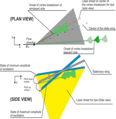
The dye visualization technique is defined as the method which gives preliminary or qualitative information about flow structures over the delta wing. In the present study, dye experiments were performed by using fluorescent dye which changes color and shines under the laser sheet. Fluorescent dye is arranged by mixing powder of Rodamine 6G with water. Dye was injected in the test region by taking the advantage of fluorescent dye reservoir height. Furthermore, continuous laser source was used during the dye observations. Dye experiments were carried out in side view plane as seen in Figure 5. Laser sheet was set by passing through the center of leading edge vortex and laser sheet is perpendicular to the plane of the delta wing. Flow structure was observed by ejecting Rodamine 6G dye which was illuminated by laser sheet in the test region. A small size needle and plastic tube were used to eject dye. Images of hydrodynamic of flow structures were record with a SONY HD-SR1 video camera and Sony Play Memories Software was used to capture the picture of instantaneous flow data.
Fig. 5. Schematic representation of water channel during dye experiment in side view plane
Fig. 6. Schematic representation of pitching motion of delta wing and experimental set up for dye experiment
3 Result and Discussion
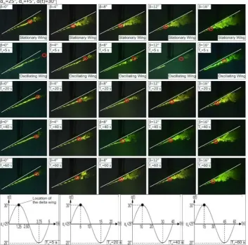
In dye visualization, the effect of yaw angle, β, period of oscillation, Te, mean angle of attack, αm amplitude of the pitching motion, αo and maximum minimum positions of vortex breakdowns are clearly seen. Vortex breakdown locations with maximum and minimum lengths are defined as maximum-minimum distances which mean that the location of vortex breakdown changes arbitrarily when delta wing is fixed at any angles of attack, α. These minimum and maximum lengths of pitching delta wing were also defined during the experiment. Figure 7 shows that vortex breakdown location in pitching delta wing motion for the maximum value of amplitude of the pitching motion, αo=+5° at a mean angle of attack, α =25° does not proceed in accordance with pitching
On the other hand, dimensionless length between vortex breakdown location and leading edge of delta wing, Xvb/C relatively increases in the case of pitching delta wing comparing to the stationary delta wing case. Here, Xvb is the length between vortex breakdown location leading edge of delta wing and C is the chord length. Onset of vortex break down occurs at about Xvb=0,75C at a static delta wing case, for angle of attack of α=25+5=30° and yaw angle of β=0° depending on the oscillation period, Te. It is clearly seen that onset of vortex breakdown moves towards apex of delta wing by providing yaw angle, β and increasing mean angle of attack, αm=25°, dimensionless number of cord length, Xvb/C regularly are decreased.
Also, effect of oscillation period on the vortex breakdown location, Xvb/C is seen in figures. Thus, it is understood that varying yaw angle, β and period of oscillation, Te, effects the variation of vortex breakdown locations.
As specified in the above Figure 7, location of vortex breakdown is shown for maximum value of amplitude of the pitching motion,
α
o=+5° or the end of the portion of cycle in which the angle of attack, α increases which is stated as upstroke. In addition, it is seen that location of vortexbreakdown, Xvb/C moves outside of the delta wing in minimum value of amplitude of the pitching motion,αo=-5° or the end of the portion of cycle in which the angle of attack, α decreases which is denoted as downstroke.
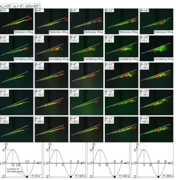
To correctly compare stationary and dynamic cases of delta wing, the value of angle of attack, α for stationary delta wing cases in dye images is similar with the minimum value of dynamic angle of attack of pitching delta wing such as α(t)=25-5=20°. Formation of onset of vortex breakdown in the cases of stationary and oscillating delta wings under variation of yaw angle, β
the delta wing to the location of Xvb=1.2C. As dye experiments demonstrate in the cases of amplitude of the pitching motion, αo=+5° (upstroke) and αo=-5° (downstroke), it was determined that effect of yaw angle, β in the case of low period ofoscillation, Te in the motion of pitching delta wing in down stroke direction.Figure 8 shows that the lower period of oscillation, Te causes a high rate ofphase differences. But the level of phase shift gets smaller for a higher time period, Te for example, in the case of 60s time period, the time lag between angles of attack, α of delta wing and onset of vortex breakdown becomes zero for αm=25°.
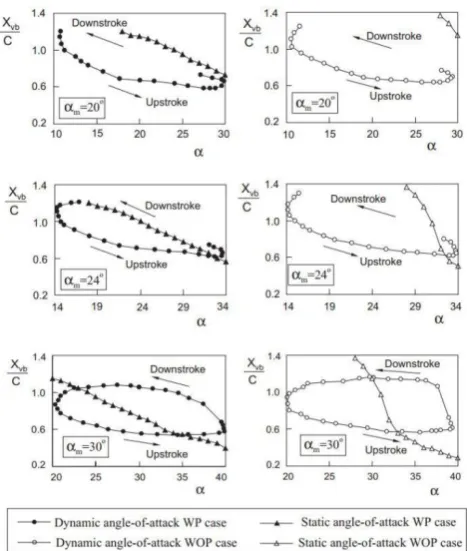
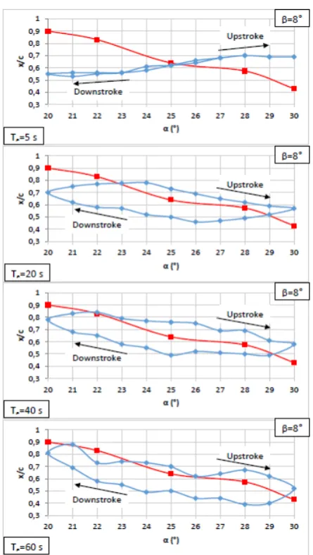
Hysteresis presented in Figure 9 to 11 demonstrates the record of locations of vortex breakdown, Xvb/C, during pitching motion of delta wing in a closed loop. When the delta wing under perturbation with a high amplitude, αm and time period, Te a time delay takes place between the position of delta wing and locations of onset of vortex breakdown comparing to the stationary delta wing. As it is shown in Figure 9, when the mean angle of attack is, αm=25°, amplitude of pitching motion is, αo=±5° and yaw angle is, β=0°, at the period of oscillation, Te =5s, there is a discrepancy between static and oscillating
wing cases caused by the dimensionless reduced frequency, K. When period of oscillation, Te, increases so the dimensionless reduced frequency, K, decreases, the large discrepancies between the locations of vortex breakdown, Xvb/C and dynamics angle of attack, α(t) disappear. The minimum dimensionless length of Xvb/C can be seen at a dynamic attack angle of α(t)=20°. At
Te=60s, the minimum dimensionless length of Xvb/C occurs at the dynamic angle of attack of α(t)=27°. However, we can conclude that the time delay decreases as the period of oscillation, Te increases. As seen, comparison of varied yaw angles, β is clearly shown in figures. During this pitching of delta wing dynamics of angles of attack changes from higher angles of attack, α and lower angles of attack, α. In both extreme cases there is leading edge vortex bursting with time delay. If we think of this unstable effect as an advantage, high performance aircraft can make certain maneuvers faster and more efficiently [11].
Whereas red line represents the stationary delta wing, blue line represents the oscillating delta wing.
Fig. 8. Formation of onset of vortex breakdown in the cases of stationary and oscillating delta wings under variation of yaw angle, β within the range of 0°≤β≤16°, period of oscillation, Te ranging from 5s to 60s at mean angle of attack, αm of 25°, amplitude of delta wing pitching motion, αo of -5° (downstroke) and dynamic angles of attack, α(t) vary between 20° and 30°. All images are taken at angle of attack, α=20°
4 Conclusions
Breakdown position of leading edge vortex on the windward side moves towards to the apex of the delta wing and vorticityconcentrations spreads over majority of the delta wing surface. But the other side of leading edge vortex moves in forward direction withoutbursting underneath the delta wing for a higher yaw angle, β. Dye visualizations show that with increasing angle of attack, α and yaw angle, β, a strong Kelvin-Helmholtz instabilities form and leading edge vortices breakdown earlier causing a large scale vorticity concentrationsand these vorticity concentrations interact with the surface of the delta wing leading to unsteady loading or buffeting the delta wing surface onthe windward side of the wing. Increasing the amplitude of the delta wing pitching motion, αo causes alterations in locations of vortex breakdowns for angles of attack, α. The locations of vortex breakdown travels towards the apex of the delta wing more closer compared with the amplitude of αo=+5°.When the delta wing is under pitching motion in upstroke or downstrokedirections, a time delay between dynamic angles of attack, α(t) and dimensionlesslength
effective in altering the location of vortex breakdown in both cases eitherthe stationary or oscillating delta wing. Leading edge vortex breakdown can be controlled partially using active or passive control techniques in order to delay onset of vortex breakdown to improve hydrodynamic performance and decline unsteady loading effects on the surface of delta wing.
In conclusions, an experimental work should be performed to control the windward side of leading edge vortex breakdown either to delay leading edge vortex bursting process or to induce onset of leading edge vortex breakdown at an earlier stage.
Acknowledgments
This study was supported by The Scientific and Technological Research Council of Turkey (TÜBİTAK) under contract number of 114M497 and Cukurova University Scientific Research Unit under contract number of FLY-2016-6283.
2. Su, W., Liu, M., & Liu, Z. Topological structures of separated flows about a series of sharp-edged delta wings at angles of attack up to 90°. Topological Fluid Mechanics, edited by H. K. Moffatt, and A. Tsinober, Cambridge Univ. Press, New York (1990). 3. NASA, (2016). Jet Exit Facility-Bubble Type Vortex
Breakdown and Spiral Type Vortex Breakdown.
https://crgis.ndc.nasa.gov/historic/Jet_Exit_Facility
4. Sarpkaya, T. On stationary and travelling vortex breakdowns. Journal of Fluid Mechanics, 45(3), 545-559. doi:10.1017/S0022112071000181 (1971). 5. Yayla, S., Canpolat, C., Sahin, B., & Akilli, H. The
effect of angle of attack on the flow structure over the nonslender lambda wing. Aerospace Science and
Technology, 28 (1), 417-430.
doi:10.1016/j.ast.2012.12.007 (2013).
6. Sahin, B., Yayla, S., Canpolat, C., & Akilli, H. Flow structure over the yawed nonslender diamond wing.
Aerospace Science and Technology, 23(1), 108-119. doi:10.1016/j.ast.2011.06.008 (2012).
7. Karasu, I. Effect of yaw angle on vortex formaton over a slender delta wing. Çukurova University Institute of Natural and Applied Sciences, Ph. D. Thesis, Adana, 159p (2015).
8. Woodiga, S., Liu, T., Ramasamy, R. S. V., & Kode, S. K. Effects of pitch, yaw, and roll on delta wing skin friction topology. Proceedings of the Institution of Mechanical Engineers, Part G: Journal of Aerospace Engineering, 230(4), 639-652. doi:10.1177/0954410015594823 (2016).
9. Canpolat, C., Sahin, B., Yayla, S., & Akilli, H. Effects of perturbation on the flow over nonslender delta wings. 45th AIAA Fluid Dynamics Conference, 1-10 (2015)
10.Ozgoren, M., & Sahin, B. (2002). Effect of pitching delta wing on vortex structures with and without impingement plate. Turkish J. Eng. Env. Sci., 26, 325- 343.
11.LeMay, S. P., Batill, S. M., & Nelson, R. C. (1990). Vortex dynamics on a pitching delta wing. Journal of Aircraft, 27(2), 131-138. doi:10.2514/3.45908 12.Canpolat C., Yayla S., Sahin B., Akilli H., “Effects
of Trailing-Edge Attachment on the Flow Structure over a Generic Delta Wing” Journal of Aerospace Engineering 30, 06017003, 2017
13.Yayla S., Canpolat C., Sahin B., Akilli H.,” Yaw Angle Effect on Flow Structure over the Nonslender Diamond Wing” AIAA JOURNAL, Vol.48, No.10,pp2457-2461,2010
14.Canpolat C., Yayla S., Sahin B., “Observation of the Vortical Flow over a Yawed Delta Wing”, Journal of Aerospace Engineering, Vol. 25, Issue. 4, pp. 613-626, 2012
15.Canpolat C., Yayla S., Sahin B., Akll H., "Dye Visualization of the Flow Structure over a Yawed Nonslender Delta Wing" Journal of Aircraft, Vol. 46, No.5, September-October 2009.
16.Karasu, I, Tasci M., O., Sahin, B., and Akilli H., Stereo PIV investigation on windward side leading edge vortex of a yawed slender delta wing, Conferences on Advances in Mechanical
Engineering, 11-13 May 2016, Yildiz Technical University, Istanbul, Turkey
17.Sahin, B., Taşc., M., O., Karasu, I., Akll H., Flow structures in end-view plane of slender delta wing, Experimental Fşuid Mechanics 2016, November 15-18, 2016 Czech Republic
Fig. 10. Comparisons of static and dynamic loops of vortex breakdown as a function of angle of attack, α. Mean angle of attack is αm=25°, amplitude of pitching motion is αo=±5°, yaw angle is β=8°, period of oscillation is Te=5s, 20s, 40s, 60s and reduced frequency is K= 0.16, 0.25, 0.49, 1.96