127
Power System Loss Minimization by Using UPFC Placed
at Optimal Location Given by Artificial Bee Colony
Algorithm
Bairu Vijay Kumar
EEED, Kakatiya Institute of Technology and Science, Warangal, India. Email: [email protected]
Abstract: In this paper, heuristic technique based minimization of losses in the power system using Unified Power Flow Controller is proposed. Here, the Artificial Bee Colony Algorithm (ABC) optimizes the location of the UPFC, while the generator outage occurs. The optimum location is referred as the maximum power loss bus, because the generator outage affects the power flow constraints like power loss, voltage magnitude, real and reactive power. By using UPFC at the optimum location minimum power loss is attained. Then UPFC is placed in the optimum location and the corresponding results are analyzed. The proposed method is implemented in the MATLAB/Simulink platform and the performance is evaluated by using the comparison power loss at different conditions. The comparison results demonstrate the superiority of the proposed approach and confirm its potential to solve the problem.
Index words: UPFC, ABC, power loss, power flows. 1. INTRODUCTION
The amount of electric power, that can be passed on between two positions via a transmission network is limited by safety and steadiness constraints [1]. Electric power systems have been forced to work to more or less their full capacities around the world due to the environmental and economic limitations to upright new generating plants and transmission lines [2] [3]. Power flow in the lines and transformers should not be allowed to increase to a level where a arbitrary incident could cause the network fall down as cascaded outages [4] [5]. For managing the power transmission system, Flexible Alternating Current Transmission System (FACTS) is a fixed device that is applied [6] [7]. FACTS is recognized as "a power electronic based system and other fixed device that present control of one or more AC transmission system parameters to develop controllability and magnify power transfer capability” [8]. UPFC is one of the FACTS devices that can administer the power flow in transmission line by including active and reactive voltage component in chain with the transmission line [9].
An optimal location of UPFC device allows to control its power streams for a interconnected network, and as a result to increase the system load ability [10]. The optimal location and optimal capacity of a particular number of FACTS in a power system is a hinder of combinatorial revise [11]. Different types of optimization algorithms have been used to effort out this kind of problem, such as genetic algorithms, reproduced annealing, tabu search and etc. [12]. This paper proposes a heuristic method for minimizing power loss of the power system using UPFC. The novelty of the proposed method is to use the Artificial
Bee Colony Algorithm to find optimal location of UPFC under generator outage conditions. When the generator outage occurs, which in turn affects the power flow constraints like voltage, power loss, real and reactive power? For improving the system performance, UPFC is placed in the optimum location given by ABC algorithm. The objective of this paper is to improve the power flows and reduce the power loss. The rest of the paper is organized as follows: Past to current exploration works are discussed in section 2. Section 3 deals with UPFC structure, problem formulation and algorithm. Section 4 gives the results and within section 5 the paper is usually concludes.
2. RECENT RESEARCH WORK: A BRIEF REVIEW
Numbers of related works are available in literature, which based on improving the power transfer capability of power system. Some of them are reviewed here.
128 A.R. Phadke et al. have suggested an approach
regarding engagement and sizing of shunt FACTS controller by means of Fuzzy logic and Real Coded Genetic Algorithm [15]. A fuzzy appearance index according to distance to impede node bifurcation, voltage profile and capacity of shunt FACTS controller is proposed. The proposed strategy has been used with IEEE 14-bus along with IEEE 57-bus test systems. To work out the optimal power flow (OPF) problems, a competent and dependable evolutionary based strategy has been suggested by Sanjeev Kumar et al. [16]. The combination of Fuzzy Systems with Genetic Algorithm (GA) and Particle Swarm Optimization (PSO) algorithm for optimal setting of OPF problem control variables.
B.Vijay kumar et al have attempted the problem of optimal location of UPFC to improve power system voltage stability using Artificial Bee Colony algorithm [17]. They were carried out simulation studies on IEEE 14 bus system.
3. UPFC STRUCTURE AND POWER FLOW MODEL
The UPFC consists of two identical inverters, i.e., parallel inverter and series inverter, which are connected in parallel and series to power systems through corresponding power transformers. The UPFC is connected between the buses
i
andj
through the series and parallel power transformers [18], the structure of the UPFC is described in the figure 1. The parallel inverter can operates either voltage controller or constant reactive power source. It injects constantpositive or negative reactive power at
i
th bus reactive power (Qi) and regulates the voltage of the bus. The series inverter independently controls the active power)
(
P
j and reactive power(
Q
j)
of the thj
bus at associated settings, which distinguishes the UPFC from the STATCOM and SSSC. Also the series inverter isused to regulate the difference between the
i
th busvoltage (Vi) and
j
th bus voltage(
V
j)
bus. TheUPFC installation structure in power system is given in the figure 1.
Figure.1 UPFC installation in power system
By using the load flow solution, the real and reactive power at the bus
i
andj
is calculated. The importance of the power injection representation is that the symmetric characteristics of admittance matrix will not be destroyed [18].The problem formulation of loss minimization is briefly explained in the following section 3.1.
3.1 Problem Formulation
The Power system loss minimization is a nonlinear optimization problem. To achieve this, control variables should be maintained at the secure limits. The control variables in terms of a certain objective function are various equality and inequality constraints. The required objective function is mathematically described in the following equations (3.1), (3.2) & (3.3)
)
,
(
t
u
F
Minimize
(3.1)0
)
,
(
t
u
g
to
Subject
(3.2)0
)
,
(
t
u
h
(3.3) Where, F(t,u) is the objective function of the power system stability, which minimizes the power system loss and voltage deviation under generator outage conditions. The outage of generator(s) causes increase in the power loss and increase in voltage deviations at buses, which affects the dynamic stability of the system. Here two objective functions are considered. First one is minimization of system loss and second one is minimization of voltage deviations at all the buses in the power system. Then, g(t,u) are the equality constraints and h(t,u) are the inequality constraints. The active power loss, equality and inequality constraints are explained in the following section.3.1.1 Objective function
129
E N k ij j i j i kloss g V V VV
P ( 2 2 2 cos )
(3.4)
Where k= (i,j); NEis the set of numbers net work
branches, gk is the conductance of branch k. θijis the
voltage angle difference between bus i and j.
3.1.2 Equality constraints
This section explains the power system equality constraints. Here, in the power system the generators need to ensure the customers total demand and the transmission loss. It is also known as power balance condition of the power system. The required power balance equations are given below.
B B N i i L D N i iG P P
P
1 1
)
( (3.5)
Where,
P
Gi is the power generated in thei
th bus,P
Dis the demand,
P
Li is the real power loss of thei
th bus.The inequality constraints are explained in the following section.
3.1.3 Inequality Constraints
This section explains the inequality constraints [19] of the power system, i.e., voltage, real and reactive power, transformer Tap limits. These constraints should be maintained within the limits to maintain the system stability. Power system stability mainly considers the voltage stability at every node, hence bus voltage limits are mainly considered in the problem. For the stable operation of power system, bus voltage should be min max
i i
i V V
V
. Normally voltage limit of every node may be 0.95 to 1.05 pu. Other Inequality constraints are given below.
Vimin ≤ Vi ≤ Vimax Bus voltage limits (3.6)
Ti min ≤ T
i ≤ Ti max
Tap position limits (3.7) Qi
min ≤ Q i ≤ Qi
max
Reactive power generation (3.8) Pimin ≤ Pi ≤ Pimax active power generation (3.9)
These constraints are satisfied under normal stable condition. During the generator outage condition, the power flow constraints are affected, which makes increase in power loss. In these conditions, the power system loss can be minimized by connecting an UPFC at optimal location. This can be achieved using proposed ABC algorithm.
3.2 Determination of optimum location of UPFC using ABC algorithm
In the proposed heuristic algorithm, the first stage involves finding normal power flows using N-R load flows. Then generator outage is introduced, power flows and power loss are determined using the Newton-Raphson (N-R) algorithm. At this condition optimal location of UPFC is determined using ABC algorithm subjected to required objective function i.e.
minimization of system power loss. The algorithmic steps to optimize the location are given in the following section.
3.2.1 Steps to determine optimum location of UPFC using ABC algorithm
Step1: Initialize the population of the line power loss and voltage at all the buses.
Step 2: Generate the random number of population input voltage and the power loss.
Step 3: The employ bee phase evaluates the fitness of the population and the required fitness function is given in the following equation (3.10) [20].
E N k ij j i j i kloss g V V VV
P ( 2 2 2 cos ) (3.10)
Step 4: Set the iteration count as 1, i.e., iteration I=1.
Step 5: Repeat
Step 6: The onlooker bee attains the elite fitness function of the bus system and improves the velocity of the populations using the following equation (3.11).
)
(
, ,, ,
,j i j i j i j k j
i
x
x
x
v
(3.11) Where, k signifies the solution in the neighborhood of i, ψ is a a random number in the range [-1, 1],)
3
,
2
,
1
(
n
k
andj
(
1
,
2
,
3
n
)
, the randomly chosen index and vij is the neighborhoodsolution of xi.
Step 7: Apply the selection process to find the better fitness of the new solutions and determine the probability.
n i y probabilit 1 (3.12)Step 8: If better solutions are not achieved, abandon the solutions and produce the random number of scout bee solution using the following equation (3.13).
)
](
1
,
0
[
max minmin
j j
j j
i
x
rand
x
x
x
(3.13)Step 9: Memorize the best solution achieved so far.
Step 10: Check the iteration range, if the iteration has not achieved the maximum range, increase the iteration count I=I+1, or else terminate the process.
Once the above process is finished, the system is ready to produce the maximum power loss bus at the specified generator bus fault condition. The optimum sizing of the UPFC is selected as per the following section.
Once the above process is completed, the system is ready to give optimum placing of the UPFC. The proposed ABC algorithm is implemented in the MATLAB platform and its performance is checked with various operating conditions. It is given in the following section.
130 The proposed ABC algorithm is implemented in
MATLAB platform. The numerical results of the proposed ABC algorithm are presented and discussed in this section. The obtained results are compared with different individual algorithms. Here, the ABC algorithm is applied to the IEEE 30 bus system. The discussions about the two systems are given as follows.
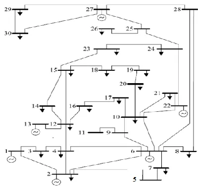
[image:4.612.74.274.175.364.2]3.3.1 Validation of results for IEEE 30 bus system with ABC algorithm
Figure 2 Structure of the IEEE 30 bus system
The Structure of the IEEE 30 bus system is shown in Fig 2. IEEE-30 bus benchmark system consists of six generator buses, 21 load buses and 42 transmission
lines and is analyzed in this section. Initially, the system base case load flow analysis is done by the standard Newton-Raphson (N-R) algorithm. Here, the IEEE 30 bus system standard data is used. Afterwards, the generator outages (single and double) are introduced and the corresponding power flows are analyzed. Due to the generator outages the system loses increases. Increased Power loss can be minimized by connecting UPFC placed at optimal location, which can be determined by the proposed ABC algorithm. Single generator outage
In this case at a time one generator is given outage and corresponding stability is analyzed.
Table 1 shows power flows during normal condition, generator outage condition and after connecting UPFC placed at optimal location for different single generator outage conditions. Here, it is observed that power flows are improved after connecting UPFC whose location is determined by ABC algorithm.
[image:4.612.86.528.446.595.2]Table 2 shows power loss at normal condition, generator outage condition and after connecting optimal sizing of UPFC placed at optimal location for different single generator outage conditions. Here, it is observed that by connecting UPFC power loss of the system is reduced. Here, it can be observed that power loss is increased to 11.903MW during single generator outage and it is reduced to 9.233MW after connecting UPFC whose location is given by proposed ABC algorithm
Table 1 Power flow analysis for single generator outage condition with the ABC algorithm
Outage of generator at
bus no.
Optimum location of
UPFC
Power flow
During normal condition
During generator outage condition
After placing UPFC at optimal location
From bus
To bus
P (MW)
Q (MVAR)
P (MW)
Q (MVAR)
P (MW)
Q (MVAR) 2 12 15 19.675 7.789 19.797 7.755 20.457 7.715 6 5 7 23.744 13.824 24.763 14.248 21.010 17.649 13 10 22 4.043 6.617 4.044 6.581 1.316 7.105 22 12 15 19.672 7.794 19.801 7.755 20.015 7.222 27 10 22 4.044 6.618 4.044 6.581 1.704 8.118
Table 2 Power loss analysis for single generator outage condition with the ABC algorithm Outage of
generator at bus. no
Optimum location
of UPFC Power loss in MW
From bus To bus During normal condition
During generator outage condition
After placing UPFC at optimal location
2 12 15
10.809
12.766 9.219
6 5 7 12.553 8.370
13 10 22 12.794 8.346
22 12 15 11.885 8.671
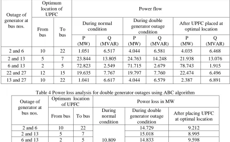
131 Table 3 Power flow analysis for double generator outages using the ABC algorithm
Outage of generator at
bus nos.
Optimum location of
UPFC
Power flow
From bus
To bus
During normal condition
During double generator outage
condition
After UPFC placed at optimal location
P (MW)
Q (MVAR)
P (MW)
Q (MVAR)
P (MW)
[image:5.612.76.535.81.365.2]Q (MVAR) 2 and 6 10 22 1.051 6.517 4.044 6.581 4.035 6.468 2 and 13 5 7 23.844 13.805 24.763 14.248 21.938 13.076 6 and 13 2 5 72.823 2.549 71.715 2.679 78.743 1.915 22 and 27 12 15 19.635 7.767 19.797 7.760 22.474 6.496 13 and 27 10 22 1.041 6.617 4.044 6.579 2.387 6.891
Table 4 Power loss analysis for double generator outages using ABC algorithm
Outage of generator at
bus nos.
Optimum location
of UPFC Power loss in MW
From bus To bus
During normal condition
During double generator outage
condition
After placing UPFC at optimal location
2 and 6 10 22
10.809
14.729 9.212
2 and 13 5 7 15.018 8.995
6 and 13 2 5 14.833 9.598
22 and 27 12 15 13.049 8.706
13 and 27 10 22 14.005 9.896
Double generator outage condition
In this case at a time two generators are given outages and corresponding stability is analyzed. Table 3 shows power flows for normal condition, double generator outage condition and after connecting UPFC whose optimal location is determined by ABC algorithm. Here, it is observed that power flows are improved after connecting the UPFC.
Table 4 shows power loss at normal condition, double generator outage condition and after connecting UPFC at optimal location which is determined by ABC algorithm. Here, it is observed that by connecting UPFC, power loss of the system is reduced. Here, it can be observed that power loss is increased to 14.005MW during double generator outage and it is reduced to 9.901MW after connecting UPFC whose location is given by proposed ABC algorithm.
Table 2 and Table 4 show effectiveness of proposed method of finding optimal placement of UPFC to reduce power loss in the system.
4. CONCLUSION
In this paper, the effectiveness of the proposed ABC algorithm to determine the optimal location of UPFC in order to minimize power loss of the power system
is presented. The advantage of this proposed heuristic algorithm is effective searching ability in order to find the optimum solutions accurately. Here, the proposed algorithm is applied to the IEEE 30 bus benchmark system and the effectiveness is tested against different generator outage conditions. Initially, single generator outage is introduced at different buses in the system and afterwards double generator outages are introduced. In all these conditions, the power loss and the power flows are analyzed. From the presented result analysis, it is concluded that, the proposed heuristic ABC algorithm is effective in minimizing power loss of the power system through the improvement in power flows by the effective determination of optimum location of UPFC.
REFERENCE
[1] P. Ramasubramanian, G. Uma Prasana, and K. Sumathi, "Optimal Location of FACTS Devices by Evolutionary Programming Based OPF in Deregulated Power Systems", British Journal of Mathematics & Computer Science, Vol.2, No.1, pp.21-30, 2012
132 & Computer Sciences, Vol.12, No.3, pp.38-49,
2012
[3] S.Durairaj, and B.Fox, "Optimal Placement of Facts Devices", International Conference on Energy & Environment, 2008
[4] D. Devaraj, and J. Preetha Roselyn, "Genetic algorithm based reactive power dispatch for voltage stability improvement", International Journal of Electrical Power & Energy Systems, Vol.32, No.10, pp.1151–1156, December 2010 [5] Chaohua Dai, Weirong Chen, Yunfang Zhu, and
Xuexia Zhang, "Reactive power dispatch considering voltage stability with seeker optimization algorithm", Electric Power Systems Research, Vol.79, No.10, pp.1462–1471, October 2009
[6] Rahul J. Shimpi, Rajendra P. Desale, Kunal S. Patil, Jaswantsing L. Rajput and Shailesh B. Chavan, "Flexible AC Transmission Systems", International Journal of Computer Applications, Vol.1, No.15, pp.54-57, 2010
[7] P. K. Dash, S. R. Samantaray, and Ganapati Panda, "Fault Classification and Section Identification of an Advanced Series-Compensated Transmission Line Using Support Vector Machine", IEEE Transaction on Power Delivery, Vol.22, No.1, pp.67-73, January 2007 [8] H O Bansal, H P Agrawal, S Tiwana, A R
Singal and L Shrivastava, "Optimal Location of FACT Devices to Control Reactive Power", International Journal of Engineering Science and Technology, Vol.2, No.6, pp.1556-1560, 2010 [9] D. Murali, and M. Rajaram, "Active and
Reactive Power Flow Control using FACTS Devices", International Journal of Computer Applications, Vol.9, No.8, pp.45-50, 2010 [10] Gerbex, S., Cherkaoui, R., and Germond,
A.J., "Optimal location of FACTS devices to enhance power system security", IEEE Bologna Power Tech Conference Proceedings, 2003 [11] Wang Feng, and Shrestha, G.B., "Allocation
of TCSC devices to optimize total transmission capacity in a competitive power market", IEEE Power Engineering Society Winter Meeting, 2001
[12] Mahdad, B., Bouktir, T., and Srairi, K., "GA Coordinated with Practical Fuzzy Rules with Multi Shunt FACTS Devices to Enhance the Optimal Power Flow", The International Conference on Computer and Tool, 2007 [13] Husam I. Shaheen, Ghamgeen I. Rashed,
and S.J. Cheng, "Optimal location and parameter setting of UPFC for enhancing power system security based on Differential Evolution
algorithm", Electrical Power and Energy Systems, Vol.33, pp.94–105, 2011
[14] Seyed Abbas Taher, and Muhammad Karim Amooshahi, "New approach for optimal UPFC placement using hybrid immune algorithm in electric power systems", Electrical Power and Energy Systems, Vol.43, pp.899-909, 2012 [15] A.R. Phadke, and Manoj Fozdar, K.R. Niazi,
"A new multi-objective fuzzy-GA formulation for optimal placement and sizing of shunt FACTS controller", International Journal of Electrical Power & Energy Systems, Vol.40, No.1, pp.46–53, September 2012
[16] Sanjeev Kumar and D.K. Chaturvedi, "Optimal power flow solution using fuzzy evolutionary and swarm optimization", International Journal of Electrical Power & Energy Systems, Vol.47, pp.416–423, May 2013 [17] B.Vijay kumar “Optimal Location of UPFC
to Improve Power System Voltage Stability Using Artificial Bee Colony Algorithm”, American Journal of Electrical Power and Energy Systems 2019; 8(2): 42-49.
[18] Wanliang Fang, and H.W. Ngan, "A robust load flow technique for use in power systems with unified power flow controllers", Electric Power Systems Research, Vol.53, No.3, pp.181-186, 2000.
[19] Chaohua Dai, Weirong Chen, Yunfang Zhu, and Xuexia Zhang, "Reactive power dispatch considering voltage stability with seeker optimization algorithm", Electric Power Systems Research, Vol.79, No.10, pp.1462–1471, October 2009.
[20] Pavlyukevich I., L´evy flights, non-local search and simulated annealing, J. Computational Physics, 226, 1830-1844 (2007).