DOI: http://dx.doi.org/10.26483/ijarcs.v8i9.4894
Volume 8, No. 9, November-December 2017
International Journal of Advanced Research in Computer Science
RESEARCH PAPER
Available Online at www.ijarcs.info
AUTOMATIC CAR PARKING USING SURF AND RANSAC ALGORITHM
Sandip Mehta
Department of Electrical and Electronics Engineering JIET Group of Institutions, Jodhpur,India
Abstract: Traffic congestion has become an unavoidable condition in large and growing metropolitan areas across the world creating parking problems. Parking a car is often a tricky task to perform. Several drivers have difficulty in parking theirs car in parallel or in reverse. Some drivers would even avoid to park their vehicles in a parking lot that requires the execution of these manoeuvres. This paper proposes an automatic car parking system using SURF and RANSAC algorithm. Here, image color enhancement is carried out by RGB to HSV conversion. The SURF feature is extracted for reference and test and finally the extraction of ROIs is done using colour normalization. The results demonstrate that if absolute sum of difference of ROIs is greater than a predetermined threshold, it would mean that the car is parked in that slot else slot is empty.
Keywords: Affine Transform, HSV, RGB, ROI, SURF, RANSAC
I. INTRODUCTION
In 2004, the Toyota Company introduced the first car into the market having an automated parking system. This operation is performed by the car's computer, with the aid of distance sensors, camera and actuators, making the parking process automated. These systems have been improving consistently over the years. However, it is only recently that they attracted public attention. Currently, many car companies are working on the realization of parking aid system and automated parking in order to facilitate the customers and stay in the competition. Their prices are rapidly declining and they will soon perhaps be optional on all vehicle models[1].
There are two kinds of parking administration systems. In the first place is a typical parking system and the other is an automatic parking System. An automatic parking system is utilized to make the entire procedure of parking cars more effective and predictable for both drivers and supervisors. This is possible through sensors at the entry and exit of the parking place, a computer operated system that deals with the entire procedure and different display boards and LEDs that help the driver to park his car[2].
A. Automated Parking
This paper discusses a project which was created as a prototype parking assistance and automated parking.
Fig.1. General operation of automated parking
This prototype was produced on a remote controlled car. Figure 1 shows thegeneral operation of automated parkingwhich was designed. In point 1 of Figure 1, the driver presses the activationbutton of the automatic parking. This enables a lateral distance sensor which measures the depth of the parking space. The side sensor is used in tandem with an encoder which measures the distance to know the length of parking. In point 2,
a signal is sent to the driver to indicate that adequate parking is detected. The driver then immobilizes the car park and accepts the proposal by pressing a particular key. Thereafter, the driver puts the car in reverse and the system parks the car automatically. When the maneuver seems dangerous, the driver can, if needed, instantly regain control of the car.
B. Parking Assist
A parking assistance system was also conducted. This system serves to help the driver when the car is parked manually. It consists of a camera filming the rear view of the car in which the image is displayed on a on-board computer. The lines representing the path that will take the car to the given set are added to this image. This will display the path that will take the car according to the movement of the steering wheel. This image allows the operator to easily choose the direction to reach the position he wants and it also allows him to identify barriers that distance sensors do not detect with automated parking. The parking assist also uses distance sensors and an alarm to signal if an obstacle is close to the car. This alarm indicates the driver to drive with caution. When the obstacle is very close to the car, a more insistent alarm is activated indicating the need to stop the vehicle immediately[3]. The distances of the obstacles are also displayed on the onboard computer. The user interface is performed on a representative on-board computer. It displays the backup camera, predicting the path and the distances measured by the distance sensors.
C. Problem Statement
in urban areas. By building a mechanized parking framework which permits high space use, less space is required contrasted with the customary car park. This is on the grounds that in the automated car parking system, the parking spot can be more minimal by having vehicles stop closer to each other. Furthermore less space is required for runways or ways in the parking spot as vehicles are exchanged to parking spots utilizing lifts and transports. Therefore, upgraded utilization of spaces can be accomplished.
Other than that, once the vehicles are in the car park, they will back off to scan for a void parking spot. This moderate moving movement will bring about the line of cars to be longer. In the end, car influx will happen when the car park is swarmed. In the computerized parking framework, the issue of congested road can be stayed away from, in light of the fact that the parking spots are found utilizing sensors. Along these lines, drivers don't have to scan for the space one by one as they are advised by the framework in regards to where the unfilled parking spot are situated before the vehicle is transported to the fancied parking spot. Along these lines, a great deal of time can be spared in the car park and vehicles are stopped proficiently by the framework. The computerized stopping framework is straightforward and advantageous for putting away vehicles in the briefest time. While the improvement of the nation and country is developing at a speedy pace, crime rates are likewise expanding every day. Subsequently, security has ended up as one of the principle worries in ordinary life of the general public. Car park is additionally one of the spots where people are assaulted every now and again[4][5]. Theft and robbery happen in car park since it is viewed as an isolated spot where relatively few individuals would be in the car stop constantly. By having an automated car park, safety for both the driver and vehicle is less at danger in light of the fact that the public is not permitted into the car park. The computerized car park can help in stopping the vehicles without the driver going into the car park[6]. In that route, security for people and vehicles are more ensured.
II. PROPOSED METHODOLOGY
The flow diagram of the proposed methodology using SURF and RANSAC algorithm is shown in fig.2.Detailed process of proposed approach is explained in following subheadings:
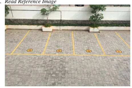
[image:2.595.331.532.52.416.2]A. Read Reference Image
[image:2.595.42.274.570.724.2]Fig. 3. Read reference image
Fig. 2. Flow diagram for proposed parking management by image processing
Here the input reference image of parking is taken from database which is an RGB image (Fig.3). It is a well known fact that the intensity of RGBcolour image varies according to intensity of sunlight. So one has to convert the reference RGB into HSV image.
B. Convert to HSV and Extract Saturation Component
In RGB to HSV conversion of reference image[7], the saturation component of HSV is taken as the saturation component does not vary according to sunlight intensity. The RGB color space can be transformed to generate other color spaces. The idea for color space transformation is to develop a model of color space that is perceptually similar with human color vision. The HSV color space is approximately perceptually uniform. In this research work, we use HSV color space to extract color features. The HSV color space is widely used in the field of color vision. The chromatic components hue, saturation and value correspond closely with the categories of human color perception (Fig. 4).
The HSV values of a pixel can be transformed from its RGB representation according to the following formula:
(1)
For 0 ≤ H ≤ 180.
Input image
Image enhancement RGB to HSV
conversion
Get saturation component of reference image
Get SURF features (points) using surf transform
Extract feature of SURF points (descriptors) for test
and reference images
Apply random sampling for inlier detection using RANSAC
algorithm
Rotate and rescale test image to overlap reference using affine
transform
Obtain ROI from both the images which is the extracted
part of the rectangular slot
Normalize both ROIs to avoid effect of shadow and whether
Convert both ROIs to Grey and find the difference between the
two ROI images
Apply threshold on ROI for particular area to find empty slot
Mark empty slot as green and occupied slot as red
End
Match SURF points with both images
Fig. 4. Saturation components of reference image
C. Apply Speeded UP Robust Feature (SURF)
[image:3.595.47.279.54.199.2]After getting the HSV image, the next step is to get SURF features (points) using Speeded UP Robust Feature (SURF) transform. SURF is additionally prominently known as inexact Scale Invariant Feature Transform (SIFT), the SIFT descriptor[8][9]. It may bean approximation of Lowe's SIFT descriptor that has been shown to be one of the most robust descriptors. Thesedescriptors have been developed so that they can be used incontexts. For this reason they are invariant by rotation andby change of scale. For our application, background subtraction,the images are always acquired on the same scale and the scene is alwaysviewed from the same angle. The SURF descriptordescribes the distribution of gradients in a neighborhoodof thepoint of interest, this is what gives it a good robustness to thechangesin brightness. First-order Haarwavelets[10] are computedin the x and y directions.The first step of calculating the descriptoris to consider a windowsquare centered on the point of interestand a width of 24 pixels. Thiswindow is divided into 4×4sub-regions in which are calculated the gradients inhorizontal andvertical direction, dx and dy as illustrated in Fig. 5.
Fig. 5. Calculating the descriptor SURF
To give more importance to the gradients close to the point of interest, these are weighted by a Gaussian centered on the point of interest and standard deviation σ = 3.3.
The final characteristic vector is the concatenation of the characteristic vectors of sixteen subregions and is therefore of dimension 16×4=64. Finally, for more invariance to the changes of contrast, the descriptor vector is normalized.
Fig. 6 shows three examples how the neighborhood of a point of interest influences the components of the descriptor of a subregion.
Fig. 6. Influence of the gradients of a sub-region on the associated descriptor vector
Subtraction of background by density of points of interest
Our first approach relies on the extraction of Harris points to which we will associate a descriptor SURF. The idea is to detect points of interest in the current image and to compare them with those of the background model. The background model must therefore be a luminance image.
Points of interest are detected with a low threshold on the Harris score in order to have points on all the textured areas of the image. However, extraction of points of interest, especially with a low threshold, is not a stable process. It is possible that a point of interest detected in the background image or the current image is not detected in the other image. For this reason, once the points of interest are detected in each of the images, we construct the list of the union of the points of interest detected in the two images. So even if a point of interest is only detected in one of the images, it will still be taken into account in both, and is thus guaranteed to have a potential candidate to match.
[image:3.595.45.283.449.596.2]Thus, the points that could not be matched show a change of texture and consequently the presence of an object of interest. We use a non-parametric estimation method (also called a kernel method) to estimate the probability density function.
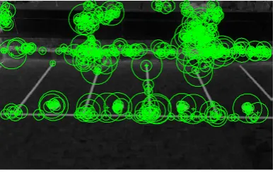
Fig. 7. SURF points in reference image
[image:3.595.337.532.451.573.2]D. Input Test Image and Repeat the Above Three Steps
Fig. 8. Test Image
[image:3.595.309.544.590.766.2]Fig. 8 shows the test image on which the RGB to HSV transform is applied and saturation component is extracted (shown in Fig. 9).
Fig. 9. Saturation component of test image
Fig. 10. Test image with SURF points
After getting the saturation components of test image, the next step is to get SURF features (points) of test image using Speeded UP Robust Feature (SURF) transform.
E. Match SURF Features in Both Images
[image:4.595.310.557.482.710.2]Next step is to match SURF points for reference image and test image.
Fig. 11. SURF matching
F. Apply Random Sampling for Inlier Detection usingRANSAC Algorithm
Fig. 12. Matched Inlier points using RANSAC algorithm
The RANdomSAmple Consensus (RANSAC) algorithmproposed by Fischler and Bolles[11]is a general parameter estimation approach designed to cope with a large proportion of outliers in the input data.
Let represent the probability that any selected data point is an inlier and
, the probability of observing an outlier.
iterations of the minimum number of points denoted are required, where,
(2)
And thus with some manipulation,
(3)
G. Rotate and Rescale Test Image to Overlap Reference using Affine Transform
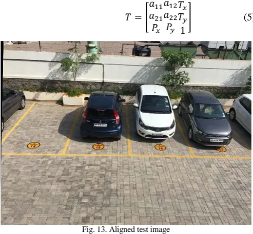
The next step is to rotate and rescale the test image to overlap the reference image. This is performed using the affine transform. An affine transformation is a function that maps an object from an affine space to another and which preserve structures.
We use a matrix: providing the changes to apply.
(4)
The vector represents the translation vector according to the canonical vectors.The vector
represents the projection vector on the basis. The square matrixcomposed by the elements is the affine transformation matrix.In image processing due to the bi-dimensional nature of images, this approach will only use a reduced version of the previous matrix:
(5)
Fig. 13. Aligned test image
H. Extraction of ROIs using Colour Normalization
After getting aligned test image, the next step is to extract Region of Interest (ROIs) from both (reference and aligned test) images and apply difference on it using colournormalization[12]. To help us derive stable colour based
[image:4.595.39.286.543.777.2]
features, it is important to understand how “colour” arises in the first place. It needs an understanding of the image formation process to model colour normalization as a process involving the interaction of three factors: light, surface, and observer (a human observer or an imaging device such as a camera). Typically imaging devices sample the incoming light using three sensors, preferentially sensitive to long (red), medium (green), and short (blue) wavelength light. These responses are denoted by R, G, and B (or just RGB) and the response of a device to light from a point in a scene is a triplet of numbers. Mathematically these responses are related to light, surface, and sensor, thus:
(6)
where is a function of wavelength λ characterizing how a given image sensor responds to the incident colour signal . The colour signal is itself the product of the light incident upon a surface (denoted ) and the reflecting properties of the surface, characterized by its surface reflectance function .
In fact, equation (6) is a very much simplified model of the image formation process, but one which suffices on many occasions. The model can be made a little more general by considering the fact that in general, the light reflected from a surface depends on the angle of the surface with respect to the light surface. Modelling this dependence on geometry is quite straightforward: the intensity of the reflected light depends on the cosine of the angle between the surface normal (a vector denoted ) and the angle of incidence of the light (a vector denoted ). The image formation equation then becomes:
(7)
Equation (7) tells us that when the surface/lighting geometry changes, sensor responses change by the same scale factor . That is, the sensor responses to a surface seen under two different lighting geometries are related by:
(8)
It is thus straightforward to remove the dependence of sensor responses on lighting geometry. For example, one can simply divide responses by the sum of the R, G, and B responses:
(9)
[image:5.595.312.569.117.347.2]And so the difference of ROIs for test and reference images is shown in Fig. 14.
Fig. 14. Difference of ROIs
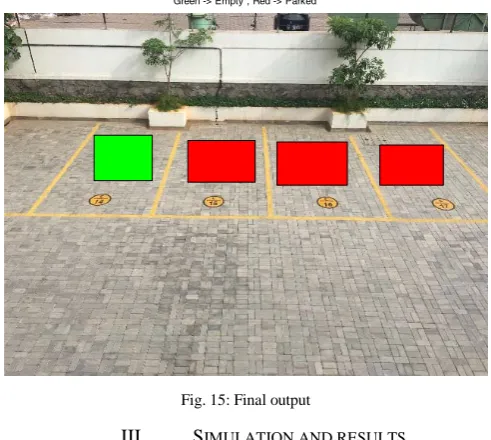
If absolute sum of difference of ROIs is greater than threshold, it means car is parked in that slot else slot is empty. Fig. 15 shows the final output.
Fig. 15: Final output
III. SIMULATION AND RESULTS
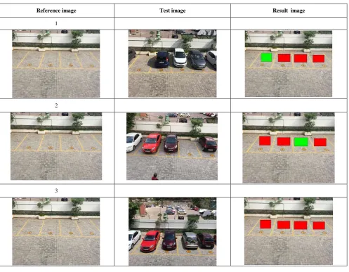
Simulation is carried out using image processing tool box of MATLAB. The table 1 shows the simulation results. It was found that if absolute sum of difference of ROIs is greater than threshold, it means car is parked in that slot else slot is empty.
Reference ROI Test ROI Difference of ROIs
Reference ROI Test ROI Difference of ROIs
Reference ROI Test ROI Difference of ROIs
Reference ROI Test ROI Difference of ROIs
[image:5.595.310.556.410.630.2]Table 1. Simulation results
Reference image Test image Result image
1
2
3
IV. CONCLUSION
An image based car parking lot management system is proposed in this research work. Different image processing method makes it possible to develop the car parking management system. In this research work, saturation component is extracted using HSV conversion of RGB image. Then SURF features are extracted and matched for both reference and test images. RANSAC algorithm is used for inlier detection in SURF matching followed by affine transform to overlap reference image and finally the extraction of ROIs is done using colour normalization. It was found that if absolute sum of difference of ROIs is greater than threshold, it means car is parked in that slot else slot is empty.
REFERENCES
[1] Li TH, Chang S.J., “Autonomous Fuzzy Parking Control of a Car-Like Mobile Robot”, IEEE Transactions on Systems, Man, and Cybernetics-Part A: Systems and Humans. Vol. 33, No. 4, pp. 451-65, July 2003.
[2] Stefan Funck, NikolausMohler and Wolfgang Oertelm, “Determining Car-Park Occupancy from Single Images”, IEEE, Intelligent Vehicles Symposium, pp. 325 – 328, June 2004.
[3] Ching-Chun Huang, Sheng-Jyh Wang, Yao-Jen Chang, and Tsuhan Chen, “A Bayesian Hierarchical Detection Framework for Parking Space Detection”, IEEE International Conference on Acoustics, Speech and Signal Processing, ISSN: 1520-6149, pp. 2097-2100, April 2008. [4] Ricardo Mejía-Iñigo, María E. Barilla-Pérez and Héctor A.
Montes-Venegas, “Color-based Texture Image Segmentation for Vehicle Detection”, IEEE, 6th International Conference on Electrical Engineering, Computing Science and Automatic Control, CCE, pp. 1-6, January 2009.
[5] Wah C., “Parking space vacancy monitoring”, Projects in Vision and Learning, 2009.
[6] Idris MY, Tamil EM, Razak Z, Noor NM, Kin LW, “Smart parking system using image processing techniques in wireless sensor network environment”, Information Technology Journal, Vol. 8, Issue 2, pp. 114-127, 2009. [7] Dong, Z. and Yong-qiang, B., 2015, July. A novel fast haze
removal technique for single image using image pyramid. In Control Conference (CCC), 2015 34th Chinese (pp. 3816-3821). IEEE.
[9] Bay, H., Tuytelaars, T. and Van Gool, L., 2006. Surf: Speeded up robust features. Computer vision–ECCV 2006, pp.404-417.
[10] Lepik, Ü., 2005. Numerical solution of differential equations using Haar wavelets. Mathematics and Computers in Simulation, 68(2), pp.127-143.
[11] Fischler, M.A. and Bolles, R.C., 1981. Random sample consensus: a paradigm for model fitting with applications to image analysis and automated cartography. Communications of the ACM, 24(6), pp.381-395.