A++ Viewer
PublisherInfo
PublisherName : Springer International Publishing PublisherLocation : Cham
PublisherImprintName : Springer
Automatic Image Interpolation Using Homography
ArticleInfo
ArticleID : 2738
ArticleDOI : 10.1155/2010/307546 ArticleCitationID : 307546
ArticleSequenceNumber : 80 ArticleCategory : Research Article ArticleFirstPage : 1 ArticleLastPage :
ArticleHistory :
RegistrationDate : 2009–7–8 Received : 2009–7–8 Revised : 2010–1–25 Accepted : 2010–4–13 OnlineDate : 2010–5–20
ArticleCopyright :
The Author(s)2010
This article is published under license to BioMed Central Ltd. This is an open access article distributed under the Creative Commons Attribution License, which permits unrestricted use, distribution, and reproduction in any medium, provided the original work is properly cited.
ArticleGrants :
ArticleContext : 136342010201011
Yi-Leh Wu,Aff1
Email: [email protected] Cheng-Yuan Tang,Aff2 Corresponding Affiliation: Aff2 Email: [email protected] Maw-Kae Hor,Aff3
Email: [email protected] Chi-Tsung Liu,Aff2
Email: [email protected]
Aff1 Department of Computer Science and Information Engineering, National Taiwan University of Science and Technology, no. 43, Section 4, Keelung Rood, Taipei 106, Taiwan,
Aff2 2Department of Information ManagementHuafan University, no. 1, Huafan Rood Shihding TownshipTaipei 2,2301Taiwanhfu.edu.tw,
Aff3 Department of Computer Science, National Cheng Chi University, no. 64, Section 2, ZhiNan Rood, Wenshan District, Taipei 11605, Taiwan,
While taking photographs, we often face the problem that unwanted foreground objects (e.g., vehicles, signs, and pedestrians) occlude the main subject(s). We propose to apply image interpolation (also known as inpainting ) techniques to remove unwanted objects in the photographs and to automatically patch the vacancy after the unwanted objects are removed. When given only a single image, if the information loss after the unwanted objects in images being removed is too great, the patching results are usually unsatisfactory. The proposed inpainting techniques employ the homographic constraints in geometry to incorporate multiple images taken from different viewpoints. Our experiment results showed that the proposed techniques could effectively reduce process in searching for potential patches from multiple input images and decide the best patches for the missing regions.
1. Introduction
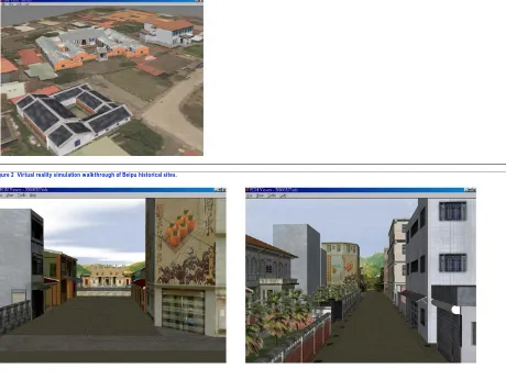
the Beipu Township, a national historical site in the Hsinchu County, Taiwan, with 3D models overlaid on satellite images. With the computerized models, visitors can walkthrough this virtualized Beipu Township as shown in Figure 2.
Figure 1 3D models overlaid on satellite image of Beipu Township, Hsinchu county, Taiwan.
Figure 2 Virtual reality simulation walkthrough of Beipu historical sites.
To make the 3D architecture models more visually realistic, 2D images are sometimes used as texture patches. But when photographs are taken, foreground objects (e.g., tourists, vehicles, signs, etc.) sometimes occlude the main subjects. Image inpainting is the process to remove unwanted objects in the photographs and to patch the vacancy.
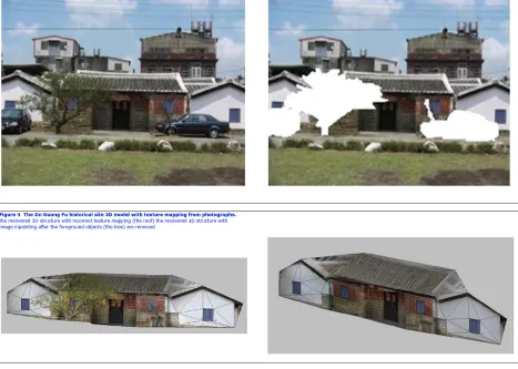
For example, Figure 3 is the Jin Guang Fu historical site in Beipu Township, a traditional Hakka culture township. In Figure 3, some trees and cars occlude the main building. The usual solution is to employ image inpainting previously proposed [1–7] to remove the unwanted trees and cars, and then patch the vacancy left behind. With image inpainting, we can correct the texture mapping problems of the reconstructed 3D models as shown in Figure 4.
Figure 4 The Jin Guang Fu historical site 3D model with texture mapping from photographs. the recovered 3D structure with incorrect texture mapping (the roof) the recovered 3D structure with image inpainting after the foreground objects (the tree) are removed
In relevant image inpainting literature, to remove damaged or undesired objects in the image, the most common method is to employ image editing tools to manually select the unwanted objects and then filled the target regions with pre-selected color. An example is shown in white in Figure 3(b). The process to patch the vacancy after unwanted objects are removed is commonly referred as image inpainting and texture synthesis in the literature [8–11].
The inpainting algorithms proposed by Oliverira et al. [1] in 2001 and the Fast Marching Method (FMM) proposed by Telea [2] in 2004 improve the speed while patching small missing or damaged regions but cause the image blurred when target regions inpainted are large.
In 2004, Criminisi et al. [3] combined the advantages of texture synthesis and image inpainting for large objects removal and inpainting. In 2005, Cheng et al. proposed a robust algorithm [4] with improved priority computation in [3]. Sun et al. (2005) proposed to first use image structure propagation and then fill the target regions [12].
In single image inpainting, the patching process relies only on the remaining image areas after undesired objects are removed. When the image information loss is too large after object removal, the patching results are usually undesirable. Some previous works also proposed the use of multiple views for inpainting [13–
15]. However, the method proposed in [13] relies mainly on landmarks matching without using any geometric constraints. In some cases, manual identification may still be required. In [14], the input is a series of images taken from a moving camera and motion-based background selection is employed, while our proposed method takes arbitrary views and do not reply on motion information. The proposed method in [15] requires multiple calibrated views where our proposed method can use uncalibrated views for inpainting. Other applications of image inpainting are to restore old films and to remove and edit image objects automatically [16, 17].
Previous research used an image for image inpainting. In this paper, we incorporate multiple images taken from different viewpoints for image inpainting. Our idea is that the regions needed for image inpainting can be correctly filled by other images taken from different viewpoints. However, incorporating multiple images taken from different viewpoints creates a challenging problem: automatic point correspondence among multiple images taken from different viewpoints is needed. In this paper, we first apply the homography property to solve the point correspondence problem among multiple images taken from different viewpoints for image inpainting. Based on the homography property, we used a robust method called the Least Median of Squares (LMedS) to achieve correct point correspondences. Our main contribution is to propose an automatic image interpolation algorithm for image inpainting.
recover missing regions in a complex scene (composed of multiple structures and textures), such as shown in Figure 5(a), the left windows in the images completely occluded by the tree in the foreground, from the remaining image areas, as shown in Figure 5(b).
Figure 5 The Jin Guang Fu historical site (a) the original image, (b) the image inpainting result with the structure propagation technique [12].
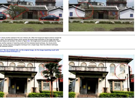
Figure 6 shows another example of the Jan A historic site. When the foreground objects severely occlude the target object, the inpainting process cannot recover the actual image information of the target area after undesired objects are removed. As shown in Figure 6(b), the image cannot be patched satisfactorily. Figure
7 shows another example of inpainting results with the exemplar-based technique, the robust priority technique, and the structure propagation technique from a single image. Note how different techniques produce unwanted artifacts.
Figure 6 The Jan A historic site, (a) the original image, (b) the image inpainting result with the exemplar-based technique [1].
The idea of using multiple images from different shooting angles is to try to recover objects that may not be occluded in all shootings. In this following section we propose to use the homography and rectification for image inpainting with multiple images.
3. Multiple View Geometry
In this section we discuss the image geometric characteristic we propose to employ in image inpainting with multiple images. Projective geometry refers to the relationship among images that are formed by the projections of the light reflection of objects in 3D space into 2D images, taken by different camera rotation and translation. We then discuss in details how to employ multiple source images in image inpainting.
3.1. Camera Geometry and Camera Model
Projective geometry is used throughout the paper to describe the perspective projection of the scene onto the images. This projection is described as follows:
(1)
where is 3 4 projection matrix describing the perspective projection process, and are vectors containing the homogeneous coordinates of the world points, and is a scale factor, respectively, image points.
When the ambiguity on the geometry is metric, (i.e., Euclidean up to an unknown scale factor), the camera projection matrices can be put in the following form:
with and indicating the position and orientation of the camera and , an upper diagonal 3 3 matrix containing the internal camera parameters:
(3)
where and represent the focal length divided by the horizontal and vertical pixel dimensions, is a measure of the skew, and is the principal point.
3.2. Two-View Geometry
Consider the image points and of a 3D point observed by two cameras with optical centers and . These five points form a common plane, that is, defined as the so-called epipolar plane. The points and are called the epipoles of the two cameras. The epipole is the projection of the optical center of the first camera in the image observed by the second camera and vise versa. If and are images of the same point, then must lie on the epipolar line associated with , that is so-called the epipolar constraint.
The epipolar constraint plays an important role in stereo vision analysis. When the internal camera parameters are known, the epipolar constraint can be represented algebraically by a 3 3 matrix, called the essential matrix. Otherwise, the epipolar constraint represented by a 3 3 matrix is called the fundamental matrix, F.
Let , be the image points on the first image and the second image, respectively. Algebraically, if and are projected from the same 3D point . Then the following equation should be satisfied:
(4)
where F is the 3 3 fundamental matrix.
3.3. Homography
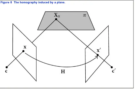
There exists a relation between the points from two images shooting from different viewing angles if the points lie on the same 3D plane. The relation could be represented as a 3×3 transformation matrix as follows, which is called the planar homography matrix (as shown in Figure 8):
(5)
where is a scalar.
Figure 8 The homography induced by a plane.
Expanding the above equation, we will derive
(6)
From (6), we have
(7)
Equation (7) can be rewritten as
(8)
(9)
If we have n matched point pairs from the same 3D plane, the above equation can be used to solve the 3 3 homography matrix H by applying the SVD method.
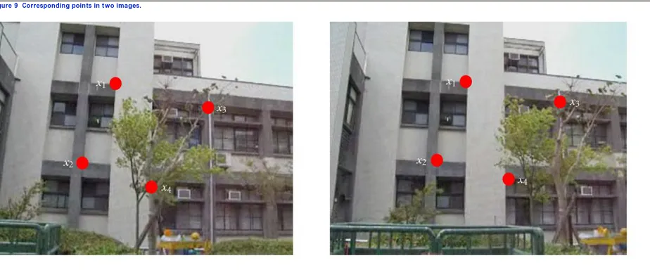
We can employ the coplanar corresponding points to determine the Homography Matrix (H), where H is a 3 3 matrix. After we decide H, we can take the point coordinate from the first images into equation and compute the corresponding coordinate in the second image, as shown in Figure 9.
Figure 9 Corresponding points in two images.
4. Image Inpainting with Multiple Images
In Section 2 we present the image inpainting results of different techniques with a single image. But for complex scenes, we show that after foreground removal, the information loss is too great that the missing regions cannot be recovered from the remaining image areas. The idea of using multiple images from different shooting angles is to try to recover objects that may not be occluded in all shootings. In this section we discuss how to apply homography and rectification for image inpainting with multiple images.Because there exist many flat surfaces where on architecture and there is a certain geometry relationship called homorgraphy, between two images, we can exploit this characteristic to locate the best fitted image patches for image inpainting.
We first take multiple images of the same objects or scenes in 3D, as depicted in Figure 10. Assuming that is a point in 3D space, since the same architecture is viewed from different angles, the corresponding point of
projected in 2D images are at different image coordinates.
Figure 10 Multiple viewing angles in an image sequence.
[MediaObjects/13634_2009_Article_2738_Fig10_HTML.]
To calculate the homography matrix H, one usually select four or more corresponding point sets manually. In the paper, we employ the automatic process to select potentially better corresponding point sets [18] to compute the homography matrix H instead of manually selecting corresponding point pairs.
First, within the selected area, we use the Sum of Squared Differences (SSD) method to locate the most likely corresponding point pairs in the two input images. The point pair with the least SSD value within there surrounding window is considered the potential corresponding point pair. The intermediate results of this step are as shown in Figure 12.
However, the SSD value can still produce erroneous corresponding point pairs because of conditions such as lighting and occlusion. We then employ the Least Median of Squares (LMedS) method to exclude the use of the corresponding point pairs to compute the homography matrix H.
(10)
A random sampling strategy similar to RANSAC is adopted because the median is not differentiable. Instead of using the consensus of all data points, sample of size is randomly selected and the corresponding homography matrix is computed. The residual errors
of all data points with respect to the homography matrix are computed and sorted in a table as shown in Figure 13. The model with the least median (minimum median residual errors) is chosen. The LMedS method can tolerate up to 50% of outliers; that is, without changing the objective function value, the LMedS method can have up to half of the data points arbitrarily far from the true estimate.
The proposed automatic process is stated as follows.
(1)Determine the features points in images with the Harris Corner Detector method (as shown in Figure 11).
(2)Select a region in the image panes. Within the selected area, use the Sum of Squared Differences (SSD) method to locate the most likely corresponding point pairs in the two input images. The intermediate results of this step are as shown in Figure 12.
(3)Use the Least Median of Squares (LMedS, as shown in Figure 13) and the bucketing method (as shown in Figure 14) to determine a better corresponding point set [19].
Figure 11 Feature points located by the Harris Corner Detector method. (a) and (b) are two sample images taken from different angles and translation(s).
[MediaObjects/13634_2009_Article_2738_Fig11_HTML.]
Figure 12 Corresponding point pairs in the selected region.
[MediaObjects/13634_2009_Article_2738_Fig12_HTML.]
Figure 13 Least Median of Squares method.
[MediaObjects/13634_2009_Article_2738_Fig13_HTML.]
Figure 14 Bucketization for corresponding point pairs selection.
[MediaObjects/13634_2009_Article_2738_Fig14_HTML.]
Median values of all runs (as shown in Figure 13) are sorted and LMedS takes the minimum of all. Six point pairs from different buckets are then randomly picked to compute H. r is defined as the residual: , where , , , are the corresponding points in image one and image two. Their homography geometry relationship is , , = . An example of the six selected point pairs is shown in Figure 15.
Figure 15 The six selected corresponding point pairs.
[MediaObjects/13634_2009_Article_2738_Fig15_HTML.]
With the homographic constraints, three or more images are taken from the image sequence with different shooting angles, as shown in Figure 16. The image on the top is the target image for inpainting. We compute the H matrix of the target image with that of the other four source images.
Figure 16 The homography matrix H among multiple images.
[MediaObjects/13634_2009_Article_2738_Fig16_HTML.]
The new coordinates are computed by interpolation as shown in Figure 17. The camera angles of the source images are then transformed to be the same as the target image, as shown in Figure 18.
Figure 17 Image transformation according to different camera angles with H.
[MediaObjects/13634_2009_Article_2738_Fig17_HTML.]
Figure 18 Image after projective transformation.
[MediaObjects/13634_2009_Article_2738_Fig18_HTML.]
During the inpainting process, the undesired objects were first manually removed as shown in Figure 19(b) and then the patching will be done automatically. The patching prioritization process determines the first position to be patched and compute the corresponding patches on the same position of the source images, as shown in Figure 20.
Figure 19 (a) the original image, (b) the image after object removal.
[MediaObjects/13634_2009_Article_2738_Fig19_HTML.]
Figure 20 Candidate patches from different source images.
[MediaObjects/13634_2009_Article_2738_Fig20_HTML.]
From multiple image patches, we employ SSD to compute the most similar patch and then fill the target area until the entire target region is patched. The intermediate inpainting result is shown in Figure 21.
Figure 21 Intermediate inpainting result.
[MediaObjects/13634_2009_Article_2738_Fig21_HTML.]
(1)Take sequential images of the objects or scenes with different shooting angles and extract the image frames, .
(2)Compute the homography geometry relationship among . (3)Use the homography matrix H to transform the source images. (4)Select manually the target region.
(5)Inpaint the target region automatically:
(a)get the contour of the target region to prioritize the patching order. Compute the target patch and the source patches;
(b)use SSD to compute the similarity of the target patch and the source patches; (c)fill the target patch with the most similar source patch.
(6)Update the target area.
(7)Repeat steps 5~6 until the entire target area is patched.
Figure 16 shows image frames taken from multiview images of architecture with different view angles. Figure 22 shows the final inpainting result that exploits the homographic constraint to fill the target image with multiple source images. But because multiple images with different angles and brightness are used as the source images, the resulting inpainted target areas may exist slightly inconsistency in terms of brightness. But the most important image information is patched completely.
Figure 22 Inpainting with homography (a) the original image, (b) the final inpainting result.
[MediaObjects/13634_2009_Article_2738_Fig22_HTML.]
Figure 23 depicts the Jan A historic site from different angles as the source images for patching and Figure 24 shows the inpainting result with our proposed technique.
Figure 23 The Jan A historic site from different angles.
[MediaObjects/13634_2009_Article_2738_Fig23_HTML.]
Figure 24 Inpainting result of the Jan A historic site (a) the original image, (b) the image after inpainting.
[MediaObjects/13634_2009_Article_2738_Fig24_HTML.]
Another experiment with a different set of source images of the Jan A historic site is shown in Figure 25. Figure 26 shows the inpainting result that utilizes the images from Figure 25.
Figure 25 Another set of images of the Jan A historic site from different angles.
[MediaObjects/13634_2009_Article_2738_Fig25_HTML.]
Figure 26 Another inpainting result of the Jan A historic site (a) the original image, (b) the image after inpainting.
[MediaObjects/13634_2009_Article_2738_Fig26_HTML.]
5. Conclusion
Traditional image inpainting techniques employ a single input image. The patching process relies only on the remaining image areas after the undesired objects are removed. When the image information loss is too great after object removal, the patching results are usually undesirable. We propose inpainting techniques that employ multiple images from different viewpoints. From multiple source images we can extract image patches that are not occluded in some images. The proposed inpainting techniques employ the homographic constraints in geometry among image frames from multiview images to assist the inpainting process. Our experiment results support that the proposed method can reduce the search process and increase the accuracy in inpainting.
Because we use multiple source images taken from different angles and under different lighting conditions, the patched area may suffer slightly inconsistency in terms of brightness. It is suggested to explore solutions to overcome this problem with increased image resolution in the future and investigate other geometric constraints that can be applied on the image inpainting process.
BodyRef
FileRef : BodyRef/PDF/13634_2009_Article_2738.pdf TargetType : OnlinePDF