Associate Professor
Dept. of Electrical and Electronic Engineering
University of Dhaka
Dr.
Mohammad
J
unaebur
R
ashid (
JR
)
1
ICT3207: Cellular and Mobile Communication (3.0 Cr)
Course Teacher
Bangladesh University of Professionals
Lecture 07
Desired C/I: Solution from simulation
ICT3207: CMC
• The required cochannel reduction factor q can be obtained from the simulation also. Let one main cell site and all six possible cochannel interferers be deployed in a pattern (Fig. 2.4).
• The distance D from the center cell to the cochannel interferers in the simulation is a variable. D = 2R can be used initially and incremented every 0.5R as D = 2R, 2.5R, 3R. For every particular value of D, a set of simulation data is generated.
• First, the location of each mobile unit in its own cell is randomly generated by a random
generator. Then the distance Dk from each of the six interfering mobile units to the center cell
site (assuming KI = 6) is obtained.
3
Lecture 07
Desired C/I: Solution from simulation
ICT3207: CMC
• Summing up all the data from six simulated interferences
and dividing it by the simulated main carrier, value C becomes C/I. This C/I is for a particular
D, the distance between the center cell site and the cochannel cell sites (cochannel
interferers).
• Repeat this process 1000 times, for each particular value of D, based on the criterion stated in Sec. 1.5 (that 75 percent of the users say voice quality is "good" or "excellent" in 90 percent of the total covered area). Assuming that mobile unit locations are chosen randomly
and uniformly, then 90 percent of the area corresponds to 900 out of 1000 mobile unit
locations.
• Then from 75 percent of the users’ opinion, C/I = 18 dB needs to be achieved with a proper value of D.
• To find a proper value for D, each mobile unit location associates with its received C/I. Some C/I values are high and some are low. This means that the lowest 100 values of C/I
Lecture 07
Desired C/I: Solution from simulation
ICT3207: CMC
• The main C/I value should be derived from the remaining 900 C/I values. This associates a particular C/I for a particular separation D.
• Repeating this process for different values of D, the corresponding mean C/I values are found. The C/I versus D curve can be plotted, depicting C/I = 18 dB as corresponding to D = 4.6R. Then
• Comparing the values of q obtained from an analytic solution (q=4.41) and q obtained from a simulation solution, the results are surprisingly close.
• Although a simulation (statistical) approach deals with a real-world situation, it does not provide a clear physical picture. The two agreeable solutions illustrated here prove that the
5
Lecture 07
Handoff Mechanism
ICT3207: CMC
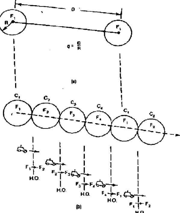
• The handoff is the process is a unique feature that allows cellular systems to operate as effectively as demonstrated in actual use. To clearly describe the handoff concept, lets consider a dimensional illustration (Fig. 2.6). The handoff concept as applied to a
one-dimensional case will also apply to two-one-dimensional cases.
• Two cochannel cells using the frequency F1 and is separated by a distance D (Fig. 2.6a). The
radius R and the distance D are governed by the value of q.
• Now we have to fill in with other frequency channels such as F2, F3, and F4 between two cochannel cells in order to provide a communication system in the whole area.
Lecture 07
Handoff Mechanism
ICT3207: CMC
Figure 2.6 Handoff mechanism. (a) Cochannel interference
reduction ratio q.
7
Lecture 07
Handoff Mechanism
ICT3207: CMC
• Suppose a mobile unit is starting a call in cell C1 and then moves to C2. The call can be dropped and reinitiated in the frequency channel from F1 to F2 while the mobile unit moves from cell C1 to cell C2. This process of changing frequencies can be done automatically by the
system without the user's intervention. This process of handoff is carried on in the cellular system.
• The handoff processing scheme is an important task for any successful mobile system. Important questions:
How does one make any one of the necessary handoffs successful?
How does one reduce all unnecessary handoffs in the system?
Lecture 07
Cell Splitting
ICT3207: CMC
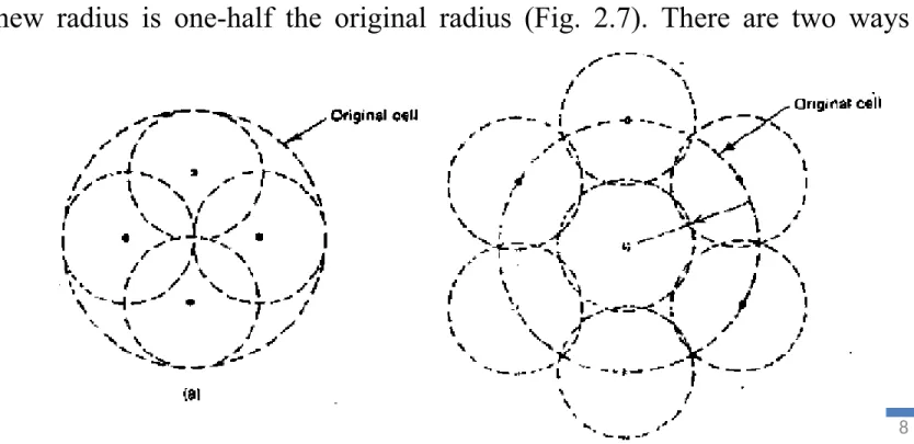
• The motivation behind implementing a cellular mobile system is to improve the utilization of spectrum efficiency. The frequency reuse scheme is one concept, and cell splitting is another concept.
• When traffic density starts to build up and the frequency channels Fi in each cell Ci cannot
provide enough mobile calls, the original cell can be split into smaller cells.
• Usually the new radius is one-half the original radius (Fig. 2.7). There are two ways of splitting:
Figure 2.7
9
Lecture 07
Cell Splitting
ICT3207: CMC
• Then based on Eq. (2.6-1), the following equation is true.
• Let each new cell carry the same maximum traffic load of the old cell; then, in theory,
• There are two kinds of cell-splitting techniques: 1. Permanent splitting
Lecture 07
Cell Splitting
ICT3207: CMC
Permanent splitting
• The installation of every new split cell has to planned ahead of time; the number of channels, the transmitted power, the assigned frequencies, the choosing of the cell-site selection, and the traffic load consideration should all be considered.
• When ready, the actual service cut-over should be set at the lowest traffic point, usually at midnight on a weekend (not in BD).
• Hopefully, only a few calls will be dropped because of this cut-over, assuming that the downtime of the system is within 2 h.
Dynamic splitting
11
Lecture 07
Components of Cellular Systems
ICT3207: CMC
• Coordinates all switch functions
• Performs all internal switching of calls
• Serves features
implemented via software
• Autonomously locates mobiles
Lecture 07
Components of Cellular Systems
ICT3207: CMC
Antennas
• Antenna pattern, antenna gain, antenna tilting, and antenna height all affect the cellular system design.
• The antenna pattern can be omnidirectional, directional, or any shape in both the vertical and the horizon planes. Antenna gain compensates for the transmitted power.
• Different antenna patterns and antenna gains at the cell site and at the mobile units would affect the system performance and so must be considered in the system design.
• The antenna patterns seen in cellular systems are different from the patterns seen in free space. If a mobile unit travels around a cell site in areas with many buildings, the
omnidirectional antenna will not duplicate the omnipattern.
13
Lecture 07
Components of Cellular Systems
ICT3207: CMC
• Antenna tilting can reduce the interference to the neighboring cells and enhance the weak spots in the cell. Also the height of the cell-site antenna can affect the area and shape of the
coverage in the system.
Switching Equipment
• The capacity of switching equipment in cellular systems is not based on the number of switch ports but on the capacity of the processor associated with the switches. In a big cellular
system, this processor should be large.
• Also it is important to consider the maximum capacity of the switching equipment.
• If the switching equipment is designed in modules, or as distributed switches, more modules can be added to increase the capacity of the equipment. For decentralized systems digital
switch may be more suitable.
• The future trend seems to be the utilization of the system handoff. This means that switching equipment can link to other switching equipment so that a call can be carried from one system
Lecture 07
Components of Cellular Systems
ICT3207: CMC
Data Links
• Each data link can carry multiple channel data (10 kbps data transmitted per channel) from the cell site to the MTSO. This fast-speed data transmission cannot be passed through a regular telephone line. Therefore data bank devices are needed.
• They can be multiplexed, many-data channels passing through a wideband T-carrier wire line or going through a microwave radio link where the frequency is much higher than 850
MHz.
15
Lecture 07
Components of Cellular Systems
ICT3207: CMC