Intergranular reheat cracking in 304H components. Experiments and damage
evaluation
M . T . C A B R I L L A T - P. A L L E G R E - E. PLUYETTE -, B. MICHEL CEA/DEN/DER - CEN Cadarache 13108 St Paul lez Durance Cedex France
A B S T R A C T
Over the past years, failure due to heat affected zone stress relief or reheat cracking in austenitic stainless steels welds, and particularly in stabilized austenitic steels like 321 or 347 have been reported world-wide. More recently similar problems have been discovered on type 316 and 304 stainless steels working in the temperature range 520-550°C.
It has been established that these cracks are generally concentrated in sites of high triaxial tension developed in the strain affected zone adjacent to welds as a result of the plastic strains introduced by the welding process, and that they are prevalent in thick sections or near very massive welds.
A specific test has been conducted on a component in 304H stainless steel. This component comprises a very massive weld in OKR3U. It was heated at 550°C and kept at this temperature for about 18000h with several stops in order to perform non destructive controls to follow the cracks evolution.
In a first part the experimental device is described, then the different tests campaigns and the results of non destructive controls are presented.
In a second part damage evaluations are explained. Residual stresses due to welding operation being important in the mechanism, it is necessary to evaluate them with refined analyses. Then the creep damage is evaluated using different damage models in order to point out the important parameters.
I N T R O D U C T I O N
Austenitic stainless steels are widely used to work at temperatures 500°C - 650°C due to their good resistance to creep and to oxidation damage in this temperature range. Nevertheless many intergranular cracks have been observed near welds, mainly for stabilised steels such as AISI 321 (stabilised with Ti) or 347 (stabilised with Nb) stainless steels (the role of these added compounds is to avoid the precipitation of chromium carbides and consequently to avoid intergranular corrosion).
The cracks were generally observed in the heat affected zone (HAZ) of thick components or of attachment welds. This form of cracking is generally referred to as reheat cracking and is associated to relaxation of residual stresses due to welding.
Reheat cracking in the stabilised austenitic stainless steels is a long-established problem and the first understanding of the mechanisms controlling this form of damage was to consider that Ti (or Nb) atoms were responsible in the following way:
during welding, the HAZ immediately adjacent to the fusion line is exposed to very high temperatures, sufficient to take the normally stable Ti (or Nb) carbides into solution. During cooling from the welding, plastic strains occur in the HAZ, but because of the high cooling rates, some of the dissolved carbides remain in solution. At the same time, high residual stresses are induced in this zone. During service life at high temperature, these stresses will relax inducing inelastic strains. Moreover, Ti (or Nb) carbides precipitate on matrix dislocations resulting in the strengthening of the grains, and leading to concentrate the creep strain arising from the stress relaxation to the grain boundaries.
For a long time, it was thought that the role of the carbides was the main factor and consequently that other austenitic steels would not present the same susceptibility to this damage. But recent studies on AISI 321 were performed in order to understand and identify more precisely the mechanisms involved in this kind of damage [1]. The conclusions were that the supposed mechanisms were not the only ones and other hypotheses were proposed: it appears that the strain hardening level is a major factor and that the cracks would result from an interaction between dislocations and C or N atoms in solution in the austenite from the beginning. There would be a solute drag effect holding up the rearrangement of the dislocations and leading to high solicitations in the grain boundary and to intergranular cavitation.
These new explanations allow to consider that the mechanisms can be the same for other austenitic steels. Studies are under development on steels of the series 300 in order to check their susceptibility to that damage and to identify creep behaviour and damage models.
SMiRT 16, Washington DC, August 2001
Paper # 1874
Concerning 304H steel, a specific program has been undertaken at CEA. Intergranular cracks have been found on a thick component after a working time of 90000h at 550°C. Metallurgical expertises and observations allow to conclude that these cracks were due to reheat cracking. An experimental test and numerical studies have been realised in order to provide elements for the comprehension of the damage observed.
This paper presents the main conclusions of this program.
E X P E R I M E N T A L RESULTS ON 304H C O M P O N E N T
Intergranular cracks have been observed during a periodic examination on a valve located on a pipe loop working at 550°C, after a period of 90000 hours at this temperature. The component was very massive and the weld concerned was made of a very large number of beads: more than 30. The parent metal was 304H and the filler metal a 19-12-2 austenitic steel named OKR3U. Composition of the 2 steels is given in table 1. The percentage of C in the parent metal is relatively high, around 0.05 %.
steel C Mn Si Cr Ni Mo S P Ti Nb B N
304H 0.047 1.21 0.69 18.6 11.5 0.34 0.023 0.025 <0.02 <0.05 0.0006 0.033
weld 0.049 1.34 0.51 18.2 11.7 1.98 0.007 0.010 . . . .
Table 1: chemical composition of the 2 steels (% in weigth)
Cracks were detected near a weld between a thick circular plate (external diameter: 680 mm, thickness: 105 mm, central hole diameter: 150 mm) and a tube (internal diameter: 150 mm, external diameter: 190 mm, length: 990 mm). A schematic view of the valve is displayed in figure 1.
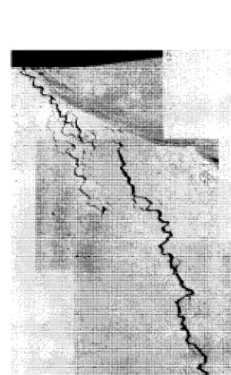
Metallurgical expertises were made. Intergranular cracks were observed along the fusion line near the surface, then oriented at about 45 ° (figure 2). The maximal depth was about 22mm, and the circumferential extension was very important: indications by dye penetrant tests affected the whole circumference. Cracks did not start from the surface, but they initiate slightly under the surface. They are located in the base metal, in the HAZ, at one or two grains from the fusion line. They are intergranular on the whole length, even in the final part of the propagation.
This problem was encountered on three valves located on three identical loops and working in the same thermal and mechanical conditions. Cracks presenting the same characteristics were discovered on the three valves. On the opposite, three valves, geometrically identical to the first ones and fabricated exactly with the same welding procedures, but which were located on loops working at a maximal temperature of 350°C did not present the same kind of damage.
Thus it appears clearly that these crackings are associated with thermo-activated phenomenon.
In a first step, numerical calculations were performed in order to estimate the creep-fatigue damage in the structure during the working period of 90000 hours, taking into account the service loadings. Stresses due to dead weight, internal pressure and thermal loadings including thermal transients for the whole working period were evaluated. These loadings were very low and they lead to small damage values, much lower than the available limits. Consequently it was not possible to explain the cracks initiation and propagation with the service loadings. Other hypotheses have to be considered.
The different observations, expertises and analyses allow to suggest that these cracks are due to the relaxation of residual stresses resulting from the welding operation. The weld is very massive, consequently the energy necessary to realise the weld is high, that induces important strain hardening in the heat affected zone and high residual stresses. During the working period at 550°C, the stress would relax, and if the , ductility of the HAZ, whose microstructure and mechanical characteristics have been modified by the hardening, is not sufficient to accommodate the inelastic strains resulting of the relaxation, cracks will initiate.
In order to bring elements to explain the development of cracks in these components a specific research program has been undertaken. Two different ways were explored:
Realisation of an experimental test on a similar component in order to check if it was possible to reproduce this kind of damage
The main purpose of these calculations is to check if the damage models are able to predict the good localisation of the damage. To obtain predictive quantitative damage values specific studies on HAZ material would be necessary to identify the actual creep behaviour and the creep damage laws. This approach has been applied to AISI 321 steel [2], [3] and has given satisfactory results. In the future, it will be applied to other steels of the series 300.
E X P E R I M E N T A L T E S T
As explained earlier, similar components located on "cold" loops were not affected by the same kind of damage. Nevertheless all the valves had been machined with the same procedures and consequently the residual stress fields induced by the welding operation are supposed to be the same for all the components. Moreover we can think that at 350°C there is no stress relaxation. Consequently for the valves which were submitted to a maximal temperature of 350°C the residual stress field has not (or almost not) been modified since the beginning.
Thus the idea was to take a valve from one of the "cold" loops, to maintain it at a temperature of 550°C and to perform regular non-destructive controls in order to be able to detect the cracks initiation and propagation.
Test device and loading conditions
A specific test device was realised. The component is of a big size, its weigh is about 500kg so it is not possible to handle it easily. During the service loading on the loops one of the main thermal loading was a thermal axial gradient along the tube. It was decided to reproduce it in the test.
For that, the sample is placed on a heating plate (power 10KW) and it is thermally insulated as shown on figure 3. The thick circular plate of the component is maintained at 550°C. Several thermocouples are settled on the specimen in order to control the heating and to record the thermal fields.
In addition, during the service life the component was submitted to several transients corresponding to the start up and the shut down of the facility. These transients are also simulated in the test in order to be representative of the real conditions. The figure 4 shows the schedule of one campaign of
test: it lasts 98 days (about 2350 h) and is divided in 5 cycles with a hold time of 425 h at 550°C for each
cycle, so a total time of 2125 h at 550°C for one campaign.
Non-destructive controls
At the same time it was necessary to develop non destructive control techniques to detect the cracks initiation and propagation but also to obtain informations on the microstructure evolution if possible. At the beginning of the study, 2 different objectives were planned:
)~ residual stress measurements using X ray diffraction or neutron diffraction methods defect detection using dye penetrant tests and ultrasonic methods
Before the first campaign an initial control was performed. It showed that it was not possible to obtain satisfactory residual stresses values with the X ray diffraction technique. That problem was linked to the metal microstructure, the grain size is coarse and consequently the results obtained are not representative of the mean strain state, they give very local informations and they are not workable to evaluate the evolution between two campaigns. This tendency was confirmed by the results obtained by the neutron diffraction method. So it was decided to give up these types of measurements afterwards.
For the defect detection, dye penetrant tests are useful only if the defects reach the outer surface of the sample. Very often, for reheat cracking, cracks initiate sub-surface. So it is necessary to use complementary detection techniques. In our case, we used ultrasonic methods: pulse-echo and TOFD (Time Of Flying Diffraction) methods which allow to obtain informations on areas located at several centimetres under the surface.
Experimental results
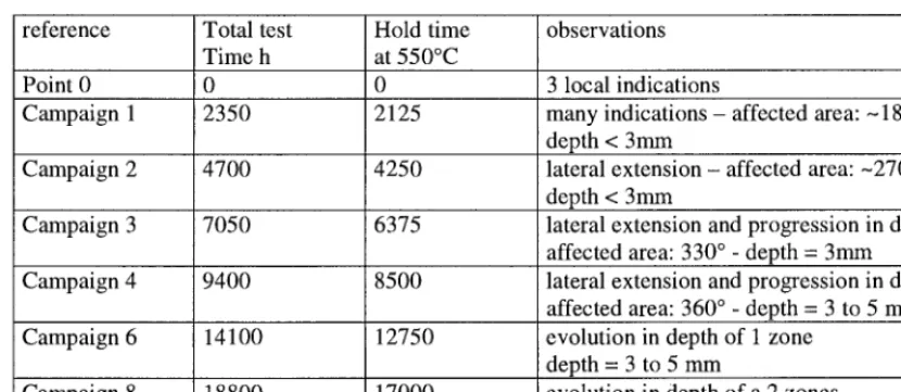
8 test campaigns were realised on the same sample, corresponding to a total time of about 17000 h at 550°C and a total time test of 18800 h. At the end of the campaigns 1, 2, 3, 4, 6 and 8, ultrasonic tests were performed. The results are summarised on figure 5 and table 2 below.
reference
Point 0 Campaign 1
Campaign 2
Campaign 3
Campaign 4
Campaign 6
Campaign 8
Total test Time h
2350 4700 7050 9400 14100 18800
Hold time at 550°C 2125 4250 6375 8500 12750 17000 observations
3 local indications many indications depth < 3mm
affected area: - 180 ° -
lateral extension depth < 3mm
affected area: --270 °
lateral extension and progression in depth affected area: 330 ° - depth = 3mm lateral extension and progression in depth affected area: 360 ° -depth = 3 to 5 mm evolution in depth of I zone
depth = 3 to 5 mm
evolution in depth of a 2 zones depth = 3 to 5 mm
Table 2: results of ultrasonic t e s t s - campaigns 1 to 8
At the end of the 8 th campaign dye penetrant tests were performed. Some defects were detected, showing that the cracks reached the surface in a few points.
The defects detected by US techniques are located in the parent metal, near the weld, as they were found on the real component in the facility.
Destructive examinations will be necessary to characterise more precisely these defects, control their localisation and obtain quantitative value of their extension. However at the end of this test campaign we can consider that it has been possible to obtain damages on a valve under the effect of residual stresses relaxation and that this type of damage arrives early in the life of the component.
N U M E R I C A L E V A L U A T I O N S
The second objective of this research program was to estimate the residual stresses due to welding and to test different creep damage models in order to check if they are able to predict correctly the localisation of the cracks.
These evaluations are made in two steps: > evaluation of residual stresses due to welding
> evaluation of stress relaxation and creep damage during hold time at 550°C
R e s i d u a l s t r e s s e s e v a l u a t i o n
The finite element calculations are performed with the CEA code CASTEM 2000. The thermomecanical model is a 2D-axisymmetrical model. The 2 materials: parent metal and weld metal are represented. The weld is realised with a large number of beads: more than 30. In the calculations it was not possible to simulate a so large number of beads. 9 "macro-beads" were represented. Figure 6 presents a view of the geometry modelised. The initial mesh includes the whole weld, but the deposit of each "macro- bead " is simulated. The chronology of the welding is respected. A succession of thermal calculations and
thermomechanical inelastic calculations corresponding to the deposit of each new "macro-bead" is performed.
We first simulate the deposit of the first bead, the other ones being represented by a "ghost material" that is to say with specific thermal and mechanical properties in order to avoid their influence: very low conductivity, very low Young modulus and high yield stress.
The thermal simulation is obtained by imposing a power density in the "macro-bead" studied. The characteristics of this heat input (power and time) are obtained from Rosenthal analytical formulas and fitted in order to obtain a fair representation of the molten area. Convective exchanges with air are also taken into account. Cooling phases between two passes are then simulated. When the interpass temperature is obtained in the whole structure, the next bead is added and the corresponding thermal calculation performed.
effect at high temperature. When the temperature approaches the melting value, hardening recovery is effective. A specific procedure has been developed in CASTEM 2000: the cumulated plastic strain is fully cancelled above 1375°C,~and partially between 1275 and 1325°C. That allows to obtain more realistic hardening rate in the HAZ and consequently more realistic stresses values.
The evolution of the thermal and mechanical properties of the 2 materials with the temperature are taken into account.
At the end of these calculations the iso-cumulated plastic strain and the iso-stresses are obtained. We observe that the maximal value of cumulated plastic strain is about 30%, in the HAZ, near the weld. The strain hardening is important in this zone, that will have consequences on the creep behaviour. We can make correlations between the experimental observations obtained on the real component in the facility and the numerical results obtained in the simulation. In the area where cracks appeared in the facility, the maximal principal stresses are tensile and oriented in such a manner that they will have a tendency to open cracks oriented as they were observed experimentally. The area where the cracks develop corresponds to the zone where all the components of the residual stresses are tensile, consequently the hydrostatic stresses and the triaxiality factor are high.
Creep damage evaluation
The structure is then heated, in order to reproduce the thermal field during hold time: the thick plate is maintained at 550°C and the axial thermal gradient along the tube is reproduced. This thermal field is maintained during 90000 h. During this time stresses will relax and inelastic strains will be created. The creep laws of the 2 materials are introduced in the model.
These results are then used to estimate creep damages using different approaches.
The following damage laws have been tested: )" RCC-MR damage law:
dt
d D = ~
TR ( O c )
with: TR = creep time to rupture for the stress Oc, dt = time during which the stress is equal to ~c, D = creep damage. When D = 1, the crack initiates.
The stress oc is an equivalent stress. Different formulations are possible. We tested 2 possibilities:
O'c -" (~vm
Gc = ~.Crvm + ~.ch + (1-C~-I3).3.GH
with: Gvm = equivalent Von Mises stress, G1 = maximal principal stress, on = hydrostatic stress
)" EMP damage law [8]
a modified version of this model was also tested in order to increase triaxiality effect:
d D - a(cYl )~13~ e x p d e c
O'vm
with: ec = equivalent creep strain, A, o~, ~ material constants and <o> indicates the positive part. Creep damage is effective only if the maximal principal stress is tensile.
In this model, we consider that cracks initiate when the damage reaches a critical value Dc
)" British Energy damage law [7]
British Energy developed a damage law based on the ductility exhaustion approach. Effect of stress multiaxiality is introduced through the Spindler fraction.
d D - dec
Ef
with: ~;f = creep ductility taking account of the multiaxial stress state. This value is linked to the uniaxial creep ductility t~funi with the Spindler fraction f: Ef = f. Efuni
[( )1 E( 1
f - e x p p 1 or1 e x p q(~vm
2
l~vmWith this approach, the creep ductility is strongly reduced in areas where stresses triaxiality is important.
Results of creep damage evaluation
The different models presented in previous section have been tested. Many results were obtained. The main conclusions are the following ones:
A good localisation of maximal creep is predicted by the models in which hydrostatic stress is introduced to take account of the stress triaxiality effect. Other models are not satisfactory. )~ The Spindler fraction is a good indicator of the reheat cracking risk. If f < 0.3, there is a high
sensitivity to reheat cracking.
Specific tests on simulated HAZ are necessary to identify completely the damage models in order to obtain predictive estimations of the creep damage.
CONCLUSIONS
Intergranular cracks due to reheat cracking have been detected on a component in 304H, after a working time of 90000 h at 550°C. A specific experimental test allowed to reproduce this kind of damage on a similar component in which the residual stresses due to welding had not yet relaxed.
Numerical analyses were performed in order to estimate the residual stresses due to welding and the creep damage during the hold time at high temperature.
These calculations allow to make correlations between the area where cracks developed and the zone where stresses triaxiality is important, and also where strain hardening is important. Moreover it appears clearly that it is necessary to introduce the effect of triaxiality in the damage models in order to predict correctly the zones where creep damage will cumulate preferentially.
Specific tests are necessary to characterise more precisely the behaviour and the damage laws of the HAZ.
REFERENCES
1. Chabaud-Reytier, M., "Etude de la fissuration diff6r6e par relaxation d'un acier inoxydable aust6nitique stabilis6 au titane", Th~se en Sciences et G6nie des Mat6riaux de l'Ecole Nationale Sup6rieure des Mines de Paris, 1999
2. Chabaud-Reytier, M., Allais, L., Poquillon, D., Caes-Hogrel, C., Mottot, M., Pineau, A., "Modelling Creep Damage in Heat Affected Zone in 321 Stainless Steel. Part 1: Quantitative Study of Intergranular Damage", Material at High Temperature, to be published in 2001
3. Poquillon, D., Chabaud-Reytier, M., Allais, Pineau, A., "Modelling Creep Damage in Heat Affected Zone in 321 Stainless Steel. Part21:Application to Creep-Crack Initiation Simulations", Material at High Temperature, to be published in 2001
4. Baup, O., "Welding Numerical S i m u l a t i o n - Development and validation of Lumping Bead Methods", Sixth International Conference on Residual Stresses, ICRS6, 10-12 July 2000, Oxford, UK
5. Baup, O., "Welding Numerical Simulation on Plate - Development and validation of Simplified and Lumping Bead Methods", International Journal of Pressure and Piping, to be published in 2001
6. Razakanaivo, A., Desroches, X., Bois, C., Lejeail, Y., Kichenin, J., "Tubular Welding Numerical Simulation: Experimental Validation", Sixth International Conference on Residual Stresses, ICRS6, 10-12 July 2000, Oxford, UK
7. Spindler, M., Hales, R., Ainsworth, R.A., "Multiaxial Creep Fatigue Rules", Creep Fatigue Damage Rules for Advanced Fast Reactor Design, Proceedings of a Technical Committee meeting, Manchester, UK, 11-13 June 1996
(~ 244 . ~
,=. * - - ~ 420
o0 " ~ ~ 500
o4
o
* 1178 M 2~2X3 ->'
6 8 0 ~ ~,
• ~ 798
Figure 1 • schematic view of the valve
2~
---~ 7 6 =1 . . . 263,00
I
! Refractory :
I
I
H e Heating plate
apu
r ~ Insulating
ent , plate
i C o n c r e t e ~
• ~ t a n d
I
Power group
Figure 3: test device
Thermal insulation
i • •
I
reg '
ulati i Secur
I
4n. iily
! •
I I
• ' ' I " ' '
Figure 5" experimental results. Circumferencial extension of defects before test (point 0) and at the end of campaigns 1 to 4
T e m ) 6 r a t u r e ( ° C )
5 5 O
2 5 0
i i
i i i i
I I I I I
IT.~ I I I I
I ~ J , ' '
~ I I I I I
~ I I I I I
/ I i , i i
4 2 5 h 4 2 5 h 4 2 5 h 4 2 5 h 4 2 5 h
I I
I I
I I
I I
I I
I
::/ /
\
I I I I
I I I I Ii
I I
I I I I
, ,, : , , ,
! !
I I I I
I I I t - T e m n ~ v - -
i i
i
I i ! i
- I i i i i i - i i • - ~.~ F