ISSN (Online): 2319-8753 ISSN (Print) : 2347-6710
I
nternational
J
ournal of
I
nnovative
R
esearch in
S
cience,
E
ngineering and
T
echnology
(A High Impact Factor, Monthly, Peer Reviewed Journal) Visit: www.ijirset.com
Vol. 8, Issue 4, April 2019
Basic of Automation and Robotics using
Bluetooth Controlled Robotic Arm
Naik Anish1, Narkhede Roshan 2 ,Nishad Kushal 3 , Singh Sneha 4 , Dr.Namrata Ansari5
B.E., Dept of EXTC, KJSIET, Mumbai, India1 B.E., Dept of EXTC, KJSIET, Mumbai, India2 B.E., Dept of EXTC, KJSIET, Mumbai, India3 B.E., Dept of EXTC, KJSIET, Mumbai, India4 Professor, Dept of EXTC, KJSIET, Mumbai, India5
ABSTRACT: Today, technology is rapidly increasing with human needs. Because of implementation of new technologies it makes life easier every day, and these studies are concentrated in robotic arm studies. Robot arms work with an user and some programming commands installed into the system[1]. Nowadays, the most developed field in robotic arms is used in industry and for medicine sector. The robot arm which has implemented in this project has the ability to move in 4 axis directions with 5 servo motors[3]. With the help of robotic arm one can take the desired material from one place and carry it to another place easily, and also mix it with the different types of machine.While doing this, robot control is provided by connecting to the android application via Bluetooth module connected to the basic Arduino Uno Microcontroller[2].
KEYWORDS: Robotic arm, Bluetooth module, Arduino Uno microcontroller
I. INTRODUCTION
A robotic arm is similar to the human arm. It’s functions are similar to the human arm and usually programmable; the arm may be the combination of the mechanism or may be part of a more complex robot like used in industries. The arms are connected by joints allowing either rotational motion used in articulated robots or translational (linear) [4].The joints manipulator can be considered to have a kinematic chain involved. End effector is analogous to human arm and it is the terminus of the the kinematic chain of manipulator.
II. THEORY
ISSN (Online): 2319-8753 ISSN (Print) : 2347-6710
I
nternational
J
ournal of
I
nnovative
R
esearch in
S
cience,
E
ngineering and
T
echnology
(A High Impact Factor, Monthly, Peer Reviewed Journal) Visit: www.ijirset.com
Vol. 8, Issue 4, April 2019
III.TEXTINPAINTING
Figure 1: Block Diagram of Robotic Arm
Proposed system will overcome these problems:
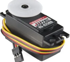
Servo Detects the operation error of a mechanism, provides feedback and corrects faults.The servo motor can be powered by AC power supply or a DC battery. The other component consist of drive and control circuits. Servo motors are beneficial for performing the tasks and applications we have in mind[1].A servo can operate steadily at small or large speeds.These motors can provide large moment from the small size. They are used in control systems such as fast operation, excessive axis movement, condition control and so on[3]. Servo motors are the mobility element of this mechanism. They are highly sensitive and are used along with electronic or programmable circuits.When the AC servo motors are brushless type motors, the servo motors brush. Servo motors have mostly three cables for connections. There is a red cable for power, black for grounding and yellow cables for control[7]. One of the servo motors used in the production phase of the project is shown in Fig.2.
ISSN (Online): 2319-8753 ISSN (Print) : 2347-6710
I
nternational
J
ournal of
I
nnovative
R
esearch in
S
cience,
E
ngineering and
T
echnology
(A High Impact Factor, Monthly, Peer Reviewed Journal) Visit: www.ijirset.com
Vol. 8, Issue 4, April 2019
The servo motor used her has a working voltage of 4.8V~7.2V and a torque of 10 kg/cm at 4.8V & 12 kg/cm at 6.6V. Servo motors are controlled using a microcontroller. In doing so, the supplied pulse width modulated is used with the data bus. Each servo motor is controlled using a PWM signal at 10-20 ms and at 0.5-1.5 ms. Different position of the robotic arm is determined according to the duration (Ts) of this signal at logic 1.
These;
● When Ts = 0.5 ms, the motor shaft rotates to the final position,
● When Ts = 0,5- 1 ms, the position of the motor shaft is in the centre position,
● When Ts = 1 - 1.5 ms, the motor shaft turns to the right for the centre position ,
● When Ts = 10-20 ms the position remains unchanged[3].
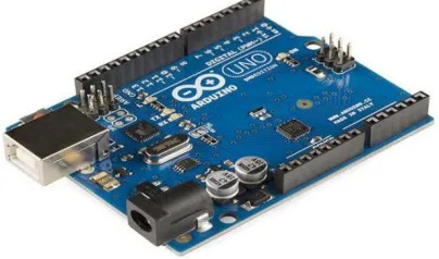
The position control of these motors is established via bluetooth module which is connected to the arduino uno. The servo motors used in the project are kept at about 5V during operation. The Microcontroller used for project controlling the Servo motor is shown in the fig below.
Figure 3: Arduino Uno Advantages-
1. Highly efficient
2. High quality of work & precision 3. Working environment is improved 4. Highly stable and constant output
5. Time constraint for working hours is removed[2] Disadvantages-
1. Decrease in job availability 2. Cost of Robotic Arm is high 3. High maintenance required[2]
Torque Calculation-
Torque is a measure of how much force are acting on an object which results in rotation of that object. Torque is denoted by T. Torque (T) is the rotational force and can be calculated using the following equation:
ISSN (Online): 2319-8753 ISSN (Print) : 2347-6710
I
nternational
J
ournal of
I
nnovative
R
esearch in
S
cience,
E
ngineering and
T
echnology
(A High Impact Factor, Monthly, Peer Reviewed Journal) Visit: www.ijirset.com
Vol. 8, Issue 4, April 2019
Where T is torque F is calculated force and L is the length from a pivot point. The force is given by acceleration of an object due to gravity (g = 9.81m/s2) multiplied by its mass.
F=M*g………. (2) Mass (M) and gravity (g)
The force (F) of an object weighed (W) is also considered W=M*g………….. (3)
Hence the torque needed to hold a mass(M) at a given distance(L) from a pivot point is given by T=(M*g)*L………… (4)
The length L considered here is the perpendicular length between the pivot point and the point where the force is applied. This equation can also be found by balancing the torque about a point.
ΣT=0=F*L–T……….. (5)
Therefore, we can replace the force (F) with mass and gravity (m*g) giving us the same equation as above.Balancing the torque about a point is the more accurate and efficient way of finding the torque.
M*g*L=TA …………... (6)
Worst case scenario must be chosen in order to estimate the torque required at each joint.
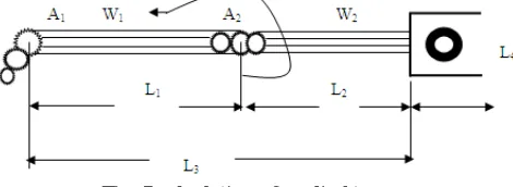
Fig. 4 required torque at each joint
The above figure concludes that a link of required length L is rotate clockwise. The force (F) is taken into account only for the perpendicular component of the length (L). We can observe that the distance of length (L) is decreasing from length L3 to length L1. Since from the torque equation given by length (L) multiplied by the force (F), the greatest value will be obtained by using L3, The force (F) does not change.The counterclockwise rotation of the link would yield the same results. The weight of the object being held as Indicated in the Figure 5 by A1, which is multiplied by the distance from its center of mass and the pivot point gives the torque required at the pivot.The torque caused by this difference masses must be added. The torque required at the first joint is therefore,
T1 = L1*A1+L1*W1 (“A” is weight of actuator or the load.) ……... (7)
We may consider that the weight A2 shown in the diagram below is not included when calculating the torque at that point. This is due to the length (L) between its center of mass and the pivot point is zero. The torque for the 2nd joint must be re-calculated with the new lengths, which is as shown in the following figure.
Fig. 5 calculation of applied torque
ISSN (Online): 2319-8753 ISSN (Print) : 2347-6710
I
nternational
J
ournal of
I
nnovative
R
esearch in
S
cience,
E
ngineering and
T
echnology
(A High Impact Factor, Monthly, Peer Reviewed Journal) Visit: www.ijirset.com
Vol. 8, Issue 4, April 2019
.The torques at each subsequent of the joint can be found similarly, by re-calculating the lengths between each new pivot point and each weight.
The Kinematics Structure of Beginner Arm-
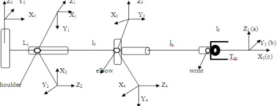
The figure.6 below demonstrates the reference and link coordinate systems of 5- DOF arm using the first step of the animator. The values of the kinematic parameters are listed below in the table (I). Where lu, ls and lf are defined as the link lengths of the shoulder of the arm, back arm and forearm respectively.
Fig. 6 The coordinate system of the arm
The coordinate transformation is describing the position and orientation of the end-effectors with respect to the base frame is given by
Suggest the basic construction of the forward kinematics function by Formulating the coordinate transformations into the one homogeneous transformation matrix. The actual description of the coordinate transformation system between frame i and frame I–1 is given by homogeneous transformation matrix.
Where S θi and C θi are Sαi and C αi , respectively.
Table 1 the parameters of the arm i θ i α a
i(mm) d i(mm)
range
1 θ 1 -90° ls 0 - 90….90° 2 θ 2 - 90° -90° 0 0 - 90°….90°
3 θ 3+180° 180° 0 lu -
ISSN (Online): 2319-8753 ISSN (Print) : 2347-6710
I
nternational
J
ournal of
I
nnovative
R
esearch in
S
cience,
E
ngineering and
T
echnology
(A High Impact Factor, Monthly, Peer Reviewed Journal) Visit: www.ijirset.com
Vol. 8, Issue 4, April 2019
Where θ is denoted by the vector of the joint variables, a, b and c. These variables are the unit vectors of the frame attached to the end- effectors.
IV.EXPERIMENTAL RESULTS
A projected robot arm and some pharmacy based drug giving robots have been developed. In addition to this, the ability to move the robot arm can be further increased, it can be used in a wide range of applications from the medical sector to the automation systems[8]. It has a quality that can be improved for more robotic systems despite the fact that the robotic arm made by this project is of prototype quality. The robotic arms sector, which is currently under development, will keep its importance in the future. The purpose of the project is to provide control of 3 axes moving robot arm design and this robot arm with a suitable micro controller and Bluetooth module with android application[6]. The necessary infrastructure has been established for the project and the necessary theoretical and practical information for this purpose has been obtained. Thus the system is utilized to recognize human motion. The proposed system can also be used to pick up object from one place to another very conveniently using the components specified in the object. For example picking up the table tennis ball and put them into the place of desired location[5]. This project offers superior controlling, easily programmable and also reliable solution to the iron based industries This project is designed in such a way that it has a good future scope and easily available .
Figure7: pick and place Robot V. CONCLUSION
Many tasks are made easier and the resulting error level has been reduced to a minimum because of robotic arms viz. a projected robot arm and some pharmacy-based drug-giving robots have been developed. Furthermore, the ability to move the robot arm can be increase and it can be used in a wide range of applications from the medical sector to the automation systems. The purpose of the project is to provide control of 3 axes moving robot arm design and this robot arm with a suitable microcontroller and Bluetooth module with android application. The necessary infrastructure has been established for the project and the necessary theoretical and practical information for this purpose has been obtained. During the process of making and developing the project, a lot of theoretical knowledge has been obtained which is relevant to the purpose of the project. They can be used in following ways for social welfare:
ISSN (Online): 2319-8753 ISSN (Print) : 2347-6710
I
nternational
J
ournal of
I
nnovative
R
esearch in
S
cience,
E
ngineering and
T
echnology
(A High Impact Factor, Monthly, Peer Reviewed Journal) Visit: www.ijirset.com
Vol. 8, Issue 4, April 2019
5. act in a human-designed environment: send the arm on a mobile base to a damaged/radioactive building and use the arm to open the door and manipulate the tools (by itself or remote controlled)
6. Manipulation(pick and place) 7. Assembly
8. Spray Painting
9. Welding(improve safety from arc burn and inhaling hazardous tubes) 10. Gluing
It also future scope such as:
● Future enhancement can include further improvement that is by adding 360 degree rotary servo motor and making it more stable. Setup can be modified that will pick more weight compared to present model.
● Ultrasonic sensor can even be placed on the arm so that it can detect and simultaneously pick the object and keep it on other place.
ACKNOWLEDGEMENT
We would like to thank EXTC Prof. Dr.Jayashree Khanapuri(HOD) and also like to thank our project guide Dr. Namrata Ansari.
REFERENCES
[1] HS Juang, KY Lurrr. Design and control of a two-wheel self-balancing robot using the Arduino microcontroller board. Control and
Automation (ICCA), 2013.
[2] R Krishna, GS Bala, SS ASC, BBP Sarma. Design and implementation of a robotic arm based on haptic technology. Int. J. of Eng. Research.
2012. 6. Electric Electronic Technology-Step and Servo Motors, SVET, 2007.
[3] Brooks, Rodney A., “New Approaches to Robotics”, Science, vol. 253, pp. 1227- 1232, 13 September, 1991.
[4] John-David Warren, Josh Adams and Harald Molle “Arduino Robotics”, Springer Science and Business Media, 2011.
[5] Patel, R. H., Desai, A. and Upadhyaya, T. (2015), A discussion on electrically small antenna property. Microw. Opt. Technol. Lett., 57: 2386–
2388. doi:10.1002/mop.29335
[6] Araújo, D. Portugal, M. Couceiro, C. Figueiredo and R. Rocha, "TraxBot: Assembling and Programming of a Mobile Robotic Platform". In
Proc. of the 4th International Conference on Agents and Artificial Intelligence (ICAART 2012), Vilamoura, Portugal, Feb 6-8, 2012.
[7] M. Quigley, B. Gerkey, K. Conley, J. Faust, T. Foote, J. Leibs, E. Berger, R. Wheeler, and A. Y. Ng, "ROS: an open-source Robot Operating
System," in Proc. Open-Source Software workshop of the International Conference on Robotics and Automation, Kobe, Japan, May, 2009. [8] P. Dalsania, B. Shah, T. Upadhyaya and V. V. Dwivedi, "Analysis of Multiband Behaviour on Square Patch Fractal Antenna," 2012