Abstract
MOSTER, JOSEPH E. Integration of a Real-Time Operating System into Automatically Generated Embedded Control System Code. (Under the direction of Dr. Charles Hall.)
The emergence of the unmanned aerial systems industry has created an increased interest in the development of autopilots for commercial use as well as research and development. One
of the core elements in the development process for an autopilot is the process used to design
and implement the flight control software. Typically, the process starts with simulation of the designed controller. Engineers are then presented with the challenge of developing software
to run on the flight hardware that accurately executes the designed controller. As further
design work is conducted, or as flight data becomes available, it is desirable to improve on the controller design and subsequently propagate those changes to the flight software. Automatic
code generation has made this process easier, but lacked the ability to provide for the
real-time needs of the controller when using lower power electronics. To address this challenge, a set of software tools was developed to modify the Simulink Real Time Workshop’s output to
integrate the generated code with a real-time embedded operating system. Testing has validated
that code is generated as intended, although the problem of software validation and verification remains an open problem in this work. The software has been successfully shown to generate
flight control code from a Simulink block diagram that was then run on an Atmega processor
© Copyright 2015 by Joseph E. Moster
Integration of a Real-Time Operating System into Automatically Generated Embedded Control System Code
by
Joseph E. Moster
A thesis submitted to the Graduate Faculty of North Carolina State University
in partial fulfillment of the requirements for the Degree of
Master of Science
Aerospace Engineering
Raleigh, North Carolina
2015
APPROVED BY:
Dr. Larry Silverberg Dr. Stephen Campbell
Acknowledgements
I would like to thank my advisor for his patience and thorough feedback. I would also like to thank my parents. Without their constant encouragement this work may never have been
Table of Contents
List of Figures . . . v
Chapter 1 Introduction . . . 1
1.1 Code Generation . . . 2
1.2 Real Time Operating System . . . 2
Chapter 2 Background. . . 4
2.1 FreeRTOS Real-Time Operating System . . . 4
2.2 Simulink Automatic Code Generation . . . 5
2.2.1 Task Generation . . . 7
Chapter 3 Implementation . . . 9
3.1 Simulink Blocks . . . 9
3.2 S-Functions . . . 12
3.3 TLC Files . . . 13
Chapter 4 Testing and Evaluation . . . 16
4.1 Context Switching . . . 16
4.2 Clock Stability . . . 17
4.3 Stack Size . . . 20
4.4 Input Sanitation . . . 21
Chapter 5 Results and Conclusion . . . 22
Bibliography . . . 24
Appendices . . . 26
Appendix A Code Compendium . . . 27
A.1 arduino srmain.tlc . . . 27
A.2 freeRTOS task.tlc . . . 28
A.3 freeRTOS nicp.tlc . . . 31
Appendix B Unit Testing . . . 32
B.1 tests . . . 32
B.2 runTest.m . . . 35
B.3 writeResult.m . . . 35
B.4 testResults.html . . . 36
B.4.1 Priority Tests . . . 36
B.4.2 Stack Size Tests . . . 37
B.4.3 Task Name Tests . . . 38
Appendix C User Guide . . . 40
C.1 General Setup . . . 40
C.1.1 Installation . . . 40
List of Figures
Figure 2.1 Overview of code generation process . . . 5
Figure 2.2 Code generation from Real-Time Workshop document . . . 6
Figure 2.3 Diagram illustrating the various types of blocks . . . 8
Figure 3.1 Top Level diagram showing a system configured for RTOS integration . . . . 10
Figure 3.2 Explicit task block mask . . . 11
Figure 3.3 Contents of a Function-Call Subsystem showing Non-Interruptible Copy blocks 12 Figure 3.4 Generated code example showing IMU Tasked.c on the left and ert main.c on the right . . . 14
Figure 4.1 Oscilloscope data showing states of the pins . . . 17
Figure 4.2 Histogram of time between interrupt triggers . . . 19
Figure C.1 An example of a simple explicit function . . . 41
Chapter 1
Introduction
Modern unmanned aerial systems have been made possible by advances in microcontroller technology that have led to small chips with ever increasing computational capabilities. A
con-sequence of this increased computational power is that microcontrollers can, and are expected
to, handle more tasks concurrently. Handling multiple tasks on a single chip eases inter-process communication and reduces the need for additional processors. This leads to smaller more power
efficient boards.
As such, an autopilot may have a variety of jobs in addition to its core task of running the flight controller. These broadly include such tasks as servicing communication requests or
supporting payloads. However, there are significant differences between these tasks in terms of
both their criticallity to flight and to their real-time requirements. The flight controller is both critical to flight and has tight time tolerences that must be met for it to function properly.
Other tasks such as servicing communications are important to the mission, but are tolerant
to greater variable delays than the flight controller. With regards to safety, although total loss of communications would disrupt a mission by potentially requiring a return-to-base or other
such contingency, it would not result in loss of control of the aircraft. Similarly, tasks such as
payload control may be caused to fail completely without affecting the ability of the vehicle to maintain safe flight. To meet the hard-real-time requirements of the flight controller, a real-time
multitasking operating system can be used.
Another development has been the ability to automatically generate control system code from a simulation model. By expanding the code generation software to interface with a
real-time operating system, an efficient tool is created for the control system developer. This thesis
1.1
Code Generation
Simulink is a powerful tool produced by Mathworks for simulating complex systems. Its block
diagram interface allows users to quickly prototype control systems and model the response. After a flight control system has been designed and tested, various strategies are used to
im-plement a physical control system that behaves the same way as the modeled system.
To implement the designed control system on flight capable hardware, the traditional design cycle has been to manually code the flight controller. This is typically done in a language such
as C that can be compiled to run on the target hardware. There are a few challenges that arise
from this process. First, the process is slow. Depending on the complexity of the control system, it can take a significant amount of time to create the final code. The implementation will also
vary from author to author, and as such may run slightly differently depending on the exact implementation. The result is that the design cycle is greatly slowed by the coding stage. A
maintenance problem is also created since changes to the Simulink model made later must be
applied manually.
An improvement on this design cycle is to automatically generate code for the flight
con-troller into embeddable functions. These functions are then manually stitched into an template
autopilot that provides the controller with state information such as sensor readings and handles the output commands generated[1]. This speeds up development and reduces time to iterate
from days to hours.
The question raised by the semi-automatic process is how much more can the process be automated. It is this fully automatic design cycle that this thesis explores. In this design cycle
the process of creating embedded code is completely automatic and transparent to the user.
The result is that the transition from Simulink to flight hardware takes seconds and makes iterating easy.
This automation is accomplished using Mathwork’s Embedded Coder software which
inte-grates automatic code generation seamlessly into the Simulink environment. The Embedded Coder supports a wide range of processors including x86, ARM, and AVR. Code can also be
generated to work with Linux or with Wind River VxWorks[2]. However, while VxWorks is an
embedded Real-Time Operating System, it cannot be run on the low-power hardware used in this project[3].
1.2
Real Time Operating System
For a control system to operate correctly there are temporal requirements that it must meet.
Sensors must be read and outputs must be generated at a specified rate otherwise the control
code so that all intermediate functions return fast enough that the operation of the critical
control system functions is not disrupted. This method does not guarantee that timings will be met and can lead to excess complexity and poor performance. A real-time operating system
(RTOS) addresses these issues.
An RTOS goes beyond a typical operating system by adding priority level as a factor in the task scheduler. This inclusion allows for higher priority tasks to interrupt lower priority tasks.
In this way, a control loop task can pause the execution of a low priority task, such as telemetry
Chapter 2
Background
This chapter explores the inner workings of the RTOS and Simulink code generation. Specifi-cally, this includes an introduction to how the RTOS handles tasks, and how Simulink generates
code from its block diagrams.
Throughout this thesis, the test hardware used was an Ardupilot Mega V1.0 with a sensor shield. This commercial-off-the-shelf board is cheap, small, and has minimal power
require-ments. The board uses the ATmega1280 chip by Atmel which, importantly, includes four 16-bit
timers that can be tied to hardware interrupts[4]. This allows an RTOS to run on the hard-ware. Additionally, Simulink supports code generation for the ATmega1280 and has a blockset
supporting several basic functions. The “Embedded Coder Support Package for Arduino”was
used with the Embedded Coder as the starting point for development.
2.1
FreeRTOS Real-Time Operating System
There are a number of RTOS on the market targeted at embedded applications. For this work, FreeRTOS was chosen for its compatibility with the test hardware and its maturity as a project.
FreeRTOS is a preemptive multitasking operating system capable of meeting hard-real-time task
requirements [5]. Since FreeRTOS is compatible with a variety of processors it was necessary to choose an appropriate port of the project that would work with the test hardware. The DuinOS
port of FreeRTOS is compatible with the AVR architecture used by the ATmega series of chips,
enabling FreeRTOS to run on the ATmega1280 chip among others [6].
Within a RTOS the functions that the OS is to run are organised into tasks. In a multitasking
OS, such as FreeRTOS, each of these tasks operates concurrently with the other tasks running
on the system. Each task is given a priority level and a stack size. By default, three priority levels are available, namely high, normal and low priority. Additional priority levels can be
of 85 bytes may be used, or for tasks needing a larger stack, the stack size can be increased.
Declaration of a task is accomplished in three steps. First a forward declaration of the task’s function is made. Then the task function is declared. This is done using a macro which wraps
the function’s content in an infinite loop [7]. Now the task may be added to the task scheduler.
This is typically done in the program’s initialization loop.
2.2
Simulink Automatic Code Generation
Although code generation is a multi-step process involving a large number of intermediate files, the process is completely automatic and transparent to the user [8]. After the user clicks the
build button, no further interaction is needed before the firmware is burned to the
microcon-troller. The process starts with the user’s Simulink model which is converted to the intermediate Real Time Workshop (RTW) document by SFunctions. The RTW document is then converted
to C using Target Language Compiler (TLC) files. In Figure 2.1 the process and associated file types are enumerated.
Figure 2.1: Overview of code generation process
In the first step, the simulink blocks are converted into the RTW format which completely
describes each block including its type, parameters, and connections to other blocks. The final
RTW document created by this process also contains global model information that includs settings and statistics of the overall model. The conversion of individual blocks is accomplished
with S-Functions associated with each type of block. This includes user defined blocks whose
conversion is handled by S-Functions that are written for each custom block.
S-Functions are software modules that are used to extend the capabilities of Simulink. By
using the S-Function API, these modules can be loaded by Simulink and communicate with
the Simulink engine. The S-Functions created for this thesis are written in C and compiled into a *.mexw32 or *.mexw64 file that Simulink can use (listed as .mex in Figure 2.1) . Using
the aformentioned S-Function API, the S-Function takes information from the Simulink block,
document. The S-Function can also be used to check for bad user inputs.
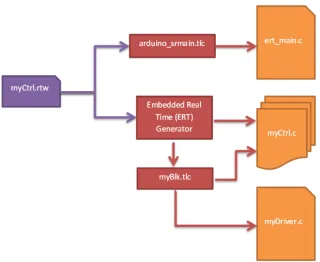
The complete RTW document is used by the Target Language Compiler to generate the embedded code. This embedded code can be divided into three groups: entry point, tasks,
and auxiliary. The flowchart in Figure 2.2 shows the transition from the RTW document to
embedded C. The RTW file is shown in purple, while the TLC files are shown in Red and the generated code is shown in orange. In this example the control system “myCtrl” has been
converted to an RTW document.
Figure 2.2: Code generation from Real-Time Workshop document
The entry point of the firmware is generated by a special TLC file specified as the “System
Target File” (STF). Its purpose is to instruct the Simulink Coder how to generate code for
particular environment [9]. For embedded applications, it is designed to setup and then execute the code at boot.
The tasks themselves are created by the Embedded Real Time (ERT) generator, a specific
set of TLC files for embedded code. This generator calls TLC files corresponding to each block described in the RTW document to generate its specific lines of code. The end result is a set
contents have the same name as the initial Simulink model, but with a different suffix and
file extension. The system model C file created contains all of the task functions as well as a function to initialize the code. A full description of all the files created by the ERT generator
is available in Mathwork’s documentation [10].
Some TLC files may also generate entirely independent C files, such as custom device drivers, that bring specific functionality to the code. In Figure 2.2 the TLC file “myBlk.tlc” generates
its own C file in addition to adding its own code into the main application.
2.2.1 Task Generation
Within the Simulink graphical environment, there isn’t normally a clear sense of tasks. To
create a semblance of tasks, it is instructive to look at when a particular block is called. From
this perspective there are three ways a block can be called for execution: once at initialization, by a function-call, or periodically based on its sample time.
The first type of blocks are called once at initialization. These are typically configuration
blocks that are needed for setup, but are not regularly run afterwards. An example of this kind of block is the “ADC Config” block in Figure 2.3. This block is responsible for setting up pins
to function as analog to digital inputs. Another type of block run at initialization are blocks
that have a sample time of “inf”. Since the output of these blocks never change, they can be initialized once at start-up.
The next way that blocks may be called is by a Function-Call block. The Function-Call
block is placed in the top level diagram and is connected to a Function-Call Subsystem block. The Function-Call Subsystem block internally contains a block diagram that is executed when
commanded to by the Functional-Call block. The Function-Call block itself determines when it
should call the blocks connected to it. As the function-call blocks are explicitly defined by the user they are referred to as explicit tasks in this paper. The function-call blocks are shown in
green in Figure 2.3.
Finally, blocks outside of a Function-Call Subsystem are called based on the sample time of the block. These blocks are given a sample time by the user or inherit a sample time that
determines how often they should run. Blocks may share the same sample time even if they
are not connected or correlated to each other. Since these blocks are grouped without regard to their function and without input from the user they are referred to in this paper as implicit
tasks.
An example of blocks that feed into implicit tasks are the “Rate Transition” blocks in Figure 2.3. Rate transition blocks are placed outside of tasks to handle the passing of data
named “Rate Trans”.
Chapter 3
Implementation
Integration of the RTOS into Simulink started at the highest level of Simulink, the diagrams. This was done to make working with the RTOS simple and intuitive for the user by presenting
the new functionality in the same way as regular Simulink blocks. The standard way of adding
new capabilities to Simulink is to add a new blockset which acts as a library for a collection of Simulink blocks. As such, a blockset was created to expose the functionality of the RTOS
as Simulink blocks. The parameters of these blocks could then be manipulated through their
“masks” which are custom defined graphical user interfaces (GUI). The blockset also included S-Functions and TLC files to integrate the information from the new blocks into the automatically
generated code.
The new “Free RTOS” blockset contains two blocks, the freeRTOS task block for setting up explicit tasks and the NICP block for inter-task communication. The freeRTOS task block was
needed so that the user defined properties of a task including name, stack size, and priority,
could be linked to a particular sub-diagram of blocks that define the functionality of the task. The NICP (Non-Interruptible Copy) block provides a mechanism for safely transferring data
between tasks. Without a mechanism such as this, data copying could be interrupted by a
context switch resulting in corruption of the information.
Additionally, modifications were made to the TLC files that were a part of the base code
generation capabilities to use the new blocks’ information in generating the structure of the
code.
3.1
Simulink Blocks
The freeRTOS task block was created as a special type of Function-Call block to define the properties of explicitly defined tasks. The user connects it to a Function-Call Subsystem block
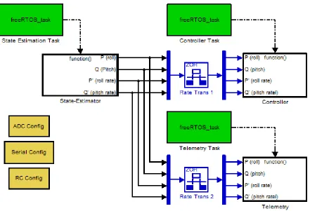
setup to generate real-time code is shown in Figure 3.1.
Figure 3.1: Top Level diagram showing a system configured for RTOS integration
In this block diagram, freeRTOS task blocks are connected to Function-Call Subsystem
blocks labeled “State-Estimator”, “Controller”, and “Telemetry”. Each of the Function-Call Subsystem blocks contain a block diagram that describes the task that the subsystem performs.
Each of these block diagrams operates at a single rate and has input and output blocks as needed
to communicate with other tasks.
To improve usability, a block mask was implemented for the freeRTOS task block. By
double-clicking on the freeRTOS task block the user can see its options as shown in Figure 3.2.
The information entered into this interface will be used by the block’s S-Function when adding the task information to the RTW file. This allows the user to easily set the task’s name,
prior-ity, and stack size. By limiting and simplifying the possible range of inputs, common errors are
level. Additionally, malformed inputs can be detected and flagged as soon as the user tries to
apply the erroneous change. For example, the stack size field only allows positive integer values to be entered. Values that include letters would be rejected.
Figure 3.2: Explicit task block mask
Another important feature was for tasks to be able to communicate with each other. This was accomplished using the standard Rate-Transition block and the NICP block.
The NICP block was placed within a task’s subsystem block immediately before any output
blocks and copies data that it receives into an output variable. Since it does so in a way that cannot be interrupted, it is guaranteed that any other task accessing the output variable will
never see a value that has been partially written to. Because the NICP block does not have any
parameters it did not need a block mask like the freeROTS task Block.
As shown in Figure 3.1, inter-task communications are connected through Rate-Transition
blocks which are located outside of any one task. This block is a standard part of Simulink and
was not subsequently modified. When triggered, the Rate-Transition block copies data from the NICP’s output variable to its own internal copy. Since blocks in top level diagram are run
at the highest priority this copy transaction cannot be interrupted. This prevents the output
of the function from being corrupted by an interrupt. The Rate-Transition blocks also satisfy a Simulink requirement to explicitly determine how block diagrams running at different rates
Finally, a second NICP block connected to the input block of the receiving task ensures
that the data being read will not be altered until it has finished making an internal copy of the data.
Figure 3.3: Contents of a Function-Call Subsystem showing Non-Interruptible Copy blocks
Beyond the FreeRTOS blockset, other blocks were created for the purposes of testing or
demonstrating functionality of the FreeRTOS blockset. These included blocks for configurating, reading, and writing to various hardware peripherals. Some examples include outputting motor
commands and reading data from the inertial measurement unit and RC receiver. Some of
these blocks for setting up peripherals during initialization are shown in Figure 3.1 with orange backgrounds.
3.2
S-Functions
For each Simulink block created there was also a corresponding S-Function that needed to be
made as well. At a minimum, each S-Function needs to define several callback methods to fulfill
its requirements as an S-Function. An S-Function may also contain functionality to validate parameters that it has been given. Since all the data gathered by the Simulink block is passed
to the S-Function, the S-Function can check the validity of the received parameters before
be thrown to describe the issue to the user. Since the NICP block does not have any parameters
that it needs to validate, it only needs to define the required callback methods[11].
The S-Function for the freeRTOS task block required much more functionality. The
valida-tion for each of the freeRTOS task S-Funcvalida-tion’s three parameters is distinct. The priority level
parameter is the easiest to validate as it must be one of only three supported values. The stack size parameter is also simple as it is only verified as being an integer greater than or equal to
the minimum size. It is important to note here that this thesis work does not handle memory
allocation issues that can arise if too much stack space is allocated across the various stacks. The more complicated parameter to check is the task name parameter. The task name
parameter will become part of the function name identifier. This function name identifier is
validated to be in compliance with the identifier rules as described in section 6.4.2 of the C99 standard ISO/IEC 9899:1999 [12]. As it is currently written, the validation is more strict than
necessary because it currently does not allow underscores in the name.
3.3
TLC Files
In the final stage of code generation, the RTW file now containing the special Simulink blocks’
data added by the S-Functions, is converted into executable code. To add support for a real time operating system it was necessary to rewrite the entry point of the code as well as provide
support for the generation of implicitly and explicitly defined tasks. This required the creation
of three TLC files, “freeRTOS task.tlc”, “freeRTOS nicp.tlc”, and “arduino srmain.tlc”. The later of which uses the same name as the stock tlc file used by Mathworks to generate non-OS
code. A line-by-line examination of “freeRTOS task.tlc” and “arduino srmain.tlc” is available
in Appendix D.
The entry point of the code, the function “main()”, is created by the arduino srmain.tlc file.
This function is responsible for setting up the environment, tasks, and starting the scheduler.
Figure 3.4 shows the main function generated for an example Simulink model “IMU tasked”. As shown in the example, the main function first calls the “init()” function to setup the basic
hardware excluding any peripherals[13].
After that, the initialization function for the model is executed; the function is named “IMU Tasked initialize” in this case. This function contains model specific code from a number
of blocks including the freeRTOS task block and is located in the “IMU Tasked.c” file. The
function allocates memory for the various structures needed and adds the explicit tasks that have been defined in the IMU Tasked.c file. It finishes by calling any block’s functions that
need to be run at initialization. This includes blocks such as those with orange backgrounds in Figure 3.1 that set up hardware peripherals.
defined in the ert main.c file. After this, the main function finishes by starting the scheduler.
This function will not return unless the scheduler is stopped by a task; a capability that is not currently made accessible to the user.
Outside of the entry point code, tasks must be declared and then added to the scheduler.
The declaration sets up the tasks loop, its timing, and establishes what code shall be run. Implicit and explicit tasks are set up differently because of the scope of information available
at different steps in the generation process. However, it is notable that the contents of both
implicit and explicit tasks are contained within the model’s C file. As such, the differences between the code structure of the two types of tasks is limited to where the tasks are declared
and then added to the scheduler.
Implicit tasks are declared in the ert main.c file by the arduino srmain.tlc. This is the only TLC file that is given access by Simulink to an array containing information on each implicit
task. This information includes the number of tasks which is used to generate the task
decla-rations for all the implicit tasks. For implicit tasks, the task declaration calls a corresponding function in the model’s C file that executes the functionality of the task.
In contrast, information on each explicit task is contained within its own section of the RTW
document corresponding to the freeRTOS block that defined it. Each instance of the freeRTOS block’s information is processed by the freeRTOS task.tlc file which creates the task definition.
Since these blocks are a part of the model definition, the resulting code is all contained within the model’s C file. The task declaration is done immediately before the declaration of the task’s
function, and the addition of the task to the scheduler is completed in the initialization function.
The final TLC file to discuss is the freeRTOS nicp.tlc file. Unlike the other TLC files dis-cussed here, this file does not modify the structure of the code. It is simply integrated as a
part of the tasks themselves. It supports safe copying of data between tasks by copying output
values into separate variables that will be read by subsequent accessors. Because it declares the copying code as “critical code”, the copying can’t be pre-empted by another task. This
guarantees that the values read by the Rate-Transition block are not part-way through being
written to. Without this protection it would be possible that an interrupt could occur between bytes of a multi-byte variable being written to memory. If the task that is now being executed
then tried to read the partially written to value, the value could be wrong. Since this error is
dependent on the coincidental alignment of an interrupt with the memory write, it can occur infrequently and randomly making it difficult to debug.
Finally, the file “arduino make rtw hook.m” was modified to allow multiple tasks to be
Chapter 4
Testing and Evaluation
After software development was completed, testing was conducted to verify the proper func-tioning of the generated code and the user interface. In particular, testing focused on context
switching, clock stability, stack sizing, and input sanitation. What follows are the details of the
tests and analysis completed to address each of these.
4.1
Context Switching
Context switching is a basic functionality that is central to the proper operation of any
multi-tasking operating system. The purpose of this test was to show that a higher priority task can interrupt the execution of a low priority task and resume its own execution. Once the higher
priority task is finished, the execution of the lower priority task should be resumed. This test
also served to demonstrate that the tasks are being executed at the proper rate.
To generate the code for this experiment, a block diagram was created with a pair of tasks
configured to each toggle an LED. The LEDs were part of the target’s hardware and were choosen for their ease of access and visual confirmation. LED A was connected to pin 37 of the
processor while LED B was connected to pin 36. The first task was given high priority and set
to execute every 10 milliseconds. This high priority task toggles LED B each time it executes. The second task was set at low priority and set to execute every 20 milliseconds. This task starts
by setting LED A high. It was designed to then use up resources by continuously checking the
clock until 16 milliseconds have passed. Once this requisite time has passed, it then sets LED A low. This is similar in concept to a spin-lock[14]. However, instead of waiting for a resource
lock to be freed it is waiting for a time interval to pass. As such, it is guaranteed that for the
high task to toggle its pin every 10 milliseconds it will have to run while the low priority task is still checking the clock.
pins driving the LEDs. The data from the oscilloscope in Figure 4.1 shows the high priority
pin’s state on channel 1 while channel 2 shows the low priority pin’s state data. The data shows that the high priority state was able to update while the lower priority task was still running.
This result is only possible by the higher priority task interrupting the execution of the lower
priority task before subsequently restoring the context of the lower priority task. This shows that context switching if functional such that both tasks were able to execute as effectively as
they would have had they been running alone.
Figure 4.1: Oscilloscope data showing states of the pins
4.2
Clock Stability
The control system being run by the RTOS is dependent on the operating system to execute it at the commanded rate. This requires that the RTOS have an accurate source for timing
information. The RTOS came configured to get its timing from an interrupt which is triggered by the 16-Bit Timer 1. The timer is configured to receive “ticks” generated by the external oscillator
installed on the test hardware. These ticks first go through a “prescaler” which generates 1 tick
before it has counted enough ticks to reach the desired time interval. The counter driven by the
ticks from the prescaler triggers the interrupt when a comparator detects that the count has reached a specified value[15]. The specified value is determined by the equation (SOURCE
-HZ/RTOS HZ)/PRESCALER-1. The RTOS frequency was set to 1000Hz to give a 1ms tick
rate with the source running at 16Mhz and the prescaler set to 64.
The following experiment was conducted to characterise the performance of the timing of the
interrupt triggering. To time the triggering of the interrupt, code was added to the FreeRTOS
function vPortYieldFromTick(). This function is a part of the port.c file in FreeRTOS which defines the chip specific code for handling context switching and interrupts. This function is
called by the Interrupt Service Routine (ISR) “TIMER1 COMPA vect” that is being triggered
every 1 ms. The modified vPortYieldFromTick function, shown below, toggles the variable “state” and then writes the result out to pin 35 (LED C). When run, pin 35 will toggle each
time the ISR is triggered making it observable using an oscilloscope. The state variable itself
is initialized at the top of the port.c file. Pin 35 was set to be a digital output by adding the necessary code to the main() function in arduino srmain.tlc. Since the control system under test
does not affect the functioning of the timing mechanism or the vPortYieldFromTick function,
the block diagram from the context switching test was used.
v o i d v P o r t Y i e l d F r o m T i c k ( v o i d ) _ _ a t t r i b u t e _ _ ( ( n a k e d ) ); v o i d v P o r t Y i e l d F r o m T i c k ( v o i d )
{
p o r t S A V E _ C O N T E X T (); v T a s k I n c r e m e n t T i c k (); // I n t e r r u p t t i m i n g c o d e s t a r t s t a t e = ! s t a t e ;
d i g i t a l W r i t e (35 , s t a t e ); // I n t e r r u p t t i m i n g c o d e end
v T a s k S w i t c h C o n t e x t (); p o r t R E S T O R E _ C O N T E X T (); asm v o l a t i l e ( " ret " ); }
Initially the oscilloscope was configured to trigger for two cases of pulse lengths; “equal to”
and “not equal to”. The oscilloscope considered the pulse length equal to 1ms if it was less than 5% from 1ms. This 5% tolerance is manufacturer defined for the TDS2022B oscilloscope used
and could not be altered[16]. The oscilloscope was calibrated prior to the experiment using the
built-in calibration source.
During the experiment, no pulses were registered in the “not equal to” case. In the “equal
to” case the average frequency was 500.42 Hz. This indicated that overall the signal was 0.1%
frequency tolerance of ±0.5% according to the crystal’s datasheet[17]. This puts the overall error of the interrupt timer within the frequency tolerance of the crystal.
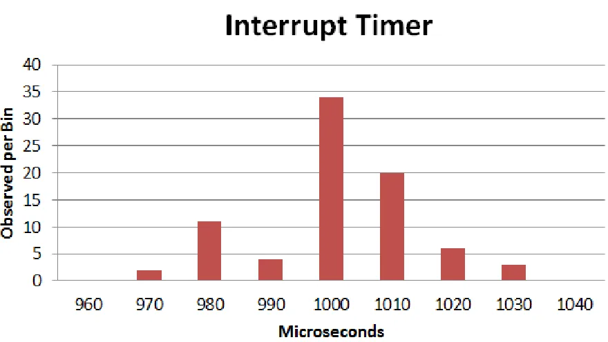
In a second experiment, the oscilloscope was used to measure the time between a pair of
interrupt triggers which yielded Figure 4.2 which shows a histogram of 80 readings. Each bin
is 10 microseconds wide and is labeled by its middle value. The data shows that the average pulse length was 1001 microseconds with a 12 microsecond standard deviation. This translates
to a 499.5±6 Hz signal which is 0.1% off from the ideal 500 Hz frequency.
Although the two experimental methods indicated errors in different directions from the ideal signal, the absolute difference is small. The data gathered in these two tests shows that
overall, the interrupt is being triggered with an acceptable level of accuracy even though the
time between any two consecutive triggers may vary. Differences in the variance could be related to small changes in temperature which can effect the frequency output of the oscillator.
4.3
Stack Size
A task with a large stack size, or the potential to grow a large stack, poses a challenge to
the operating system which must allocate enough space for the stack or risk a stack overflow condition. Although determining how much stack space to allocate is a challenge beyond the
scope of this work, it is important to demonstrate that if commanded to supply a larger stack
size, the change will be incorporated into the generated code. In this experiment, it is shown that setting an increased stack size allocation is effective in allowing a task to successfully run
that would otherwise overrunning its stack.
First, a task that will overrun its stack was created. The task reads each of six ADC channels and wrote their respective values to the serial port. The task’s stack size was set to a size of 40
bytes. A quick look at the generated code revealed that a large number of temporary variables were being instantiated. When the program was subsequently run on the microcontroller, the
program crashed immediately.
To determine that there was a stack overflow issue, the stack overflow detection capability of FreeRTOS was enabled. By enabling the configCHECK FOR STACK OVERFLOW parameter
in the FreeRTOSConfig.h file, FreeRTOS was instructed to test for stack overflow conditions.
This is accomplished by checking if the bottom of the stack that the OS has switched away from exceeds the allocation for that stack[18]. It is notable that in the event that the bottom
of the stack overflows its allocation but subsequently recedes to within its allocation before any
context switch occurs, the stack overflow will not be detected. However, while this method will not catch all stack overflows, it is sufficient for this experiment to show that there has been a
stack overflow.
When a stack overflow is detected, the function vApplicationStackOverflowHook is called. This function was then defined, as shown below, to set pin 35 (LED C) high. The hook function
was written at the end of the tasks.c file belonging to freeRTOS.
# if ( c o n f i g C H E C K _ F O R _ S T A C K _ O V E R F L O W > 0)
v o i d v A p p l i c a t i o n S t a c k O v e r f l o w H o o k ( x T a s k H a n d l e * pxTask , s i g n e d c h a r * p c T a s k N a m e ) {
// LED C = Pin 35 p i n M o d e (35 , O U T P U T ); d i g i t a l W r i t e (35 , 1); }
# e n d i f
Now, when the program was run with a stack size of 40, the program stopped within 1
second and LED C came on to indicate a stack overflow. The stack size was then increased to 140 using the “User Defined” stack size option in the task block’s mask. After the stack was
adjusted, the program was able to run without error and without triggering the stack overflow
just this information it is uncertain how much extra stack space was available. However, while
this doesn’t ensure that a stack overflow cannot happen, it does show that given a desired stack size the generated code will incorporate that change.
4.4
Input Sanitation
Verification of the final system was a significant challenge. A full verification process could include verifying the block diagram, verifying static generated code, and dynamic analysis of
code. However, for this work the focus was on verifying that the code generated by the custom blocks will be generated as designed. To this end, verification focused on unit tests designed to
capture the full range of possible user defined parameters to the S-Fuctions. Since the NICP
block did not have any parameters, it was only the three parameters of the freeRTOS task block that required validation. Successful input sanitation meant not only catching bad inputs, but
also providing usable feedback on the error to the user.
The implementation of input sanitation is discussed in Section 3.2. Should any of the input checks fail, the desired result is an appropriate error message be presented to the user. To
aid in testing this functionality, additional code was written to automatically modify block
parameters, trigger automatic code generation, and capture any errors and their associated message. The error could then be compared against the expected error for each type of invalid
block parameter. The test results were written to an html file that lists the error message and
whether the result matched the expected result will a PASS/FAIL field for each result.
The test results were broken down into three sections with each corresponding with one of
the three parameters. Since each of the checks is done independently of the other parameters it
was not necessary to test combinations of bad inputs. The net result of these tests was complete branch coverage of the code. In total, 19 unit tests were run against the FreeRTOStask block.
The scripts used to conduct the testing and the final results can be found in Appendix B. The
Chapter 5
Results and Conclusion
The tools presented here have been successful in bringing the advantages of a RTOS to auto-matically generated code. Now, a typical user can create prioritized multi-tasked code using
only the simulink interface. This has opened up the these real-time capabilities to a new class of
users including students and controls engineers who would otherwise lack the skills to implement such a system on their own. A user employing this work may focus attention on the capabilities
of the flight controller instead of on the mechanisms for actualizing it in hardware. Additionally,
the speed and ease of generation allows for quicker iteration and testing of systems. This also creates future opportunities for easier certification of flight controllers by introducing a common
tool and framework. Confidence in the system build by one user’s testing may be translated to
other user’s flight controllers as a result of their underlying similarities that result from using a common tool.
The testing conducted has validated the correct functioning of core capabilities. Among
these, context switching has been shown to be functional, thus enabling FreeRTOS to interrupt lower priority tasks to run higher priority tasks. The clock is stable enough that FreeRTOS can
use it to time when to run the tasks. The stack size settings correctly adjust the size of the
stack allocation allowing for large tasks to be run. Finally, unit testing has shown that inputs are correctly sanitized preventing unanticipated code from being generated.
Taking a broader view shows that there remain some challenges. These challenges represent
areas where future work could expand the capabilities of this project, but also areas of weakness in the generated code.
First, there are a limited number of priorities. This may pose a challenge to large control
systems needing fine control of prioritization. While the current code only supports the three default priority levels that came with FreeRTOS it would not be a significant problem to add
additional priority levels.
could be used to improve this process including static analysis and dynamic analysis tools.
These methods would have the advantage of automating the process as well as having greater confidence that the stack size will be sufficient. However, with or without these tools, it is
still advisable to eliminate potentially unbounded recursion from the control system due to the
limited amount of memory available.
For each sample time in the model, Simulink creates a corresponding implicit task. This
may result in the creation of implicit tasks that contain no code if a particular sample time
is used exclusively by explicit tasks. While creating these empty tasks is inefficient, it does not significantly impact the performance of the system. For users needing to eliminate these
inefficiencies, the empty function and task may simply be deleted from the final code manually.
Finally, the most difficult challenge to the current code is the question of the what the priority level of implicit tasks should be. The problem lies in the limited amount of information
available when generating the task code to run a particular implicit task. As the implicit tasks
are defined by the rate at which they are run, it is possible to have both high priority and low priority code in the same task. The solution has been to recommend the user to limit the
use of implicit tasks to only those blocks needed for inter-task communication since all implicit
tasks are run as high priority. While this works well for the inter-task communication blocks, there isn’t a way to enforce this rule within Simulink. However, it is not necessarily clear that
it would be desirable to obey this rule in all cases.
Recognising these challenges it is shown here that automatic code generation has potential
to accelerate research and development work with control systems. In particular, this work is
suited to the kinds of control systems that would normally be run on an 8-bit AVR. While there are limits, they do not prevent the tool from being an effective rapid prototyping tool.
And while the generated code may not be as efficient as code generated by a human expert, it
Bibliography
[1] Jinhui Hu; Dabin Hu; Jianbo Xiao. Study of real-time simulation system based on rtw
and its application in warship simulator. “Electronic Measurement & Instruments”, pages
pp.3–966,3–970, Aug 2009.
[2] Embedded Coder Supported Hardware. www.mathworks.com/products/
embedded-coder/supported/index.html, November 2012.
[3] Atmel Hardware Vendor. http://www.windriver.com/products/bsp_web/bsp_vendor.
html?vendor=Atmel&sort=6&order=1, March 2014.
[4] ATmega640/1280/1281/2560/2561 Complete. /http://www.atmel.com/Images/doc2549.pdf, August 2012.
[5] Features Overview. http://www.freertos.org/FreeRTOS_Features.html, November
2012.
[6] DuinOS Project Home. http://code.google.com/p/duinos/, November 2012.
[7] Features Overview. http://www.freertos.org/implementing-a-FreeRTOS-task.html,
November 2012.
[8] Chris Hote Tom Erkkinen. Automatic Flight Code Generation with Integrated Static
Run-Time Error Checking and Code Analysis. AIAA Modeling and Simulation Technologies
Conference and Exhibit, pages 1–2, 2006.
[9] Model Reference Simulation Targets. http://www.mathworks.com/help/simulink/ug/
model-reference-simulation-targets.html, October 2013.
[10] File and Folder Created by Build Process. http://www.mathworks.com/help/rtw/ug/
files-and-folders-created-by-the-build-process.html, November 2012.
[11] Develping S-Functions. http://www.mathworks.com/help/pdf_doc/simulink/
sfunctions.pdf, September 2013.
[12] ISO/IEC 9899:1999. http://www.iso.org/iso/iso_catalogue/catalogue_ics/
catalogue_detail_ics.htm?csnumber=29237, September 2013.
[13] Michael Margolis. Arduino Cookbook. O’Reilly, 2012.
[14] Abraham Silberschatz, Peter Baer Galvin, and Greg Gagne. Operating system concepts.
John Wiley, 2009.
[15] ATmega640/1280/1281/2560/2561 Complete. http://www.atmel.com/Images/doc2549.
pdf, October 2012.
[16] TDS2022B, TDS2024B Manual. http://www.tek.com/oscilloscope/
[17] CSTCE Series 16 MHz 2.5 X 2 mm 15 pF Built-in Capacitor SMT Resonator. http:
//search.murata.co.jp/Ceramy/image/img/w_hinm/L0430E.pdf, February 2014.
[18] Coding Conventions.http://www.freertos.org/Stacks-and-stack-overflow-checking.
html, February 2014.
[19] Coding Conventions. http://www.mathworks.com/help/rtw/tlc/
Appendix A
Code Compendium
A.1
arduino srmain.tlc
% % % % % % % % % % % % % % % % % % % % % % % % % % % % % % % % % % % % % % % % % % % % % % % % % % % % % % % % % % % % % % % % % % % % % % % % % % % % % % % % % %%
%% A b s t r a c t :
%% C u s t o m f i l e p r o c e s s i n g to g e n e r a t e a " m a i n " f i l e . %%
%% C o p y r i g h t 2 0 1 2 J o s e p h M o s t e r %%
% % % % % % % % % % % % % % % % % % % % % % % % % % % % % % % % % % % % % % % % % % % % % % % % % % % % % % % % % % % % % % % % % % % % % % % % % % % % % % % % % % s e l e c t f i l e N U L L _ F I L E
% f u n c t i o n F c n F r e e R T O S T a s k i n g M a i n () v o i d % if G e n e r a t e S a m p l e E R T M a i n
% a s s i g n C o m p i l e d M o d e l . G e n e r a t e S a m p l e E R T M a i n = T L C _ F A L S E % e n d i f
% a s s i g n c F i l e = L i b C r e a t e S o u r c e F i l e (" S o u r c e " , " C u s t o m " , " e r t _ m a i n ") % o p e n f i l e t m p B u f
# i n c l u d e "% < L i b G e t M d l P u b H d r B a s e N a m e () >. h " # i n c l u d e " W P r o g r a m . h "
# i n c l u d e " D u i n O S . h " % c l o s e f i l e t m p B u f
% < L i b S e t S o u r c e F i l e S e c t i o n ( cFile , " I n c l u d e s " , t m p B u f ) > % o p e n f i l e t m p B u f
// For e a c h t a s k
% f o r e a c h tid = L i b G e t N u m T a s k s ()
d e c l a r e T a s k L o o p ( s t e p T a s k % < tid >); t a s k L o o p ( s t e p T a s k % < tid >)
{
u n s i g n e d l o n g p r e v i o u s = m i l l i s (); % < L i b C a l l M o d e l S t e p ( tid ) >\
d e l a y (% < L i b G e t C l o c k T i c k S t e p S i z e ( tid ) >*1000 -( m i l l i s () - p r e v i o u s )); }
% e n d f o r e a c h i n t _ T m a i n ( v o i d ) {
/* I n i t i a l i z e m o d e l */ i n i t ();
% < L i b C a l l M o d e l I n i t i a l i z e () >\
% f o r e a c h l o o p I d e n t i f i e r = L i b G e t N u m T a s k s ()
c r e a t e T a s k L o o p ( s t e p T a s k % < l o o p I d e n t i f i e r > , H I G H _ P R I O R I T Y ); //1 % e n d f o r e a c h
// T a s k S c h e d u l e r v T a s k S t a r t S c h e d u l e r ();
// W i l l not get h e r e u n l e s s a t a s k c a l l s v T a s k E n d S c h e d u l e r (): for ( ; ; ) ;
//% < L i b C a l l M o d e l T e r m i n a t e () >\ r e t u r n 0;
}
% c l o s e f i l e t m p B u f
% < L i b S e t S o u r c e F i l e S e c t i o n ( cFile , " F u n c t i o n s " , t m p B u f ) > % e n d f u n c t i o n
A.2
freeRTOS task.tlc
%%
%% A b s t r a c t :
%% TLC f i l e for the f r e e R O T S _ t a s k B l o c k . %%
%% = = = = = = = = = = = = = = = = = = = = = = = = = = = = = = = = = = = = = = = = = = = = = = = = = %% F u n c t i o n : B l o c k T y p e S e t u p
%%
% f u n c t i o n B l o c k T y p e S e t u p ( block , s y s t e m ) v o i d
%% C r e a t e a g l o b a l TLC v a r i a b l e to c o u n t n u m b e r of T a s k b l o c k s % a s s i g n :: n u m T s k B l k s = 0
% e n d f u n c t i o n %% B l o c k T y p e S e t u p
%% F u n c t i o n : B l o c k I n s t a n c e S e t u p = = = = = = = = = = = = = = = = = = = = = = = = = = = = = = = = = = = = = = = = = = = = = = = = %% A b s t r a c t :
%% F i n d and c a c h e the n e e d e d B l o c k r e c o r d s and n a m e s r e l a t e d to t h i s b l o c k . %% G e n e r a t e w a r n i n g s if I / O not c o n n e c t e d .
%%
% f u n c t i o n B l o c k I n s t a n c e S e t u p ( block , s y s t e m ) v o i d % a d d t o r e c o r d b l o c k A s y n c C a l l e r G e n C o d e T L C _ T R U E
%% Get the B l o c k for the d o w n s t r e a m f - c ss , w a r n and r e t u r n if t h e r e is n o n e % if L i b I s E q u a l ( S F c n S y s t e m O u t p u t C a l l . B l o c k T o C a l l , " u n c o n n e c t e d ")
% a s s i g n w r n T x t = " The o u t p u t for F r e e R T O S T a s k b l o c k ’% < T a s k B l o c k N a m e > ’ is " ... " u n c o n n e c t e d . No c o d e w i l l be g e n e r a t e d for t h i s b l o c k ."
% < L i b R e p o r t W a r n i n g ( w r n T x t ) > % r e t u r n
% e n d i f
% a s s i g n S S B l o c k = L i b G e t F c n C a l l B l o c k ( block , 0) % a d d t o r e c o r d b l o c k s s B l o c k S S B l o c k
%% Add Task ’ s N a m e and i n f o r m a t i o n to the b l o c k % a s s i g n t a s k N a m e = S F c n P a r a m S e t t i n g s . T a s k N a m e
% a s s i g n t a s k P r i o r i t y = S F c n P a r a m S e t t i n g s . T a s k P r i o r i t y % a s s i g n t a s k S t a c k S i z e = S F c n P a r a m S e t t i n g s . T a s k S t a c k S i z e % a s s i g n b l o c k = b l o c k + t a s k N a m e
% a s s i g n b l o c k = b l o c k + t a s k P r i o r i t y % a s s i g n b l o c k = b l o c k + t a s k S t a c k S i z e %% I n c r e m e n t n u m b e r of t a s k b l o c k s % a s s i g n :: n u m T s k B l k s = :: n u m T s k B l k s + 1 % e n d f u n c t i o n
%% F u n c t i o n : S t a r t = = = = = = = = = = = = = = = = = = = = = = = = = = = = = = = = = = = = = = = = = = = = = = = = = = = = = = = = = = = = = %% A b s t r a c t :
%% C r e a t e a t a s k w i t h the d e s i r e d p a r a m e t e r s %%
% f u n c t i o n S t a r t ( block , s y s t e m ) O u t p u t {
% s w i t c h ( t a s k P r i o r i t y ) % c a s e 1
c r e a t e T a s k L o o p W i t h S t a c k S i z e (% < t a s k N a m e > _fcn , H I G H _ P R I O R I T Y ,% < t a s k S t a c k S i z e >); % b r e a k
c r e a t e T a s k L o o p W i t h S t a c k S i z e (% < t a s k N a m e > _fcn , N O R M A L _ P R I O R I T Y ,% < t a s k S t a c k S i z e >); % b r e a k
% c a s e 3
c r e a t e T a s k L o o p W i t h S t a c k S i z e (% < t a s k N a m e > _fcn , L O W _ P R I O R I T Y ,% < t a s k S t a c k S i z e >); % b r e a k
% d e f a u l t
c r e a t e T a s k L o o p W i t h S t a c k S i z e (% < t a s k N a m e > _fcn , N O R M A L _ P R I O R I T Y ,% < t a s k S t a c k S i z e >); % b r e a k
% e n d s w i t c h }
% e n d f u n c t i o n
%% F u n c t i o n : O u t p u t s = = = = = = = = = = = = = = = = = = = = = = = = = = = = = = = = = = = = = = = = = = = = = = = = = = = = = = = = = = = %% A b s t r a c t :
%% %%
% f u n c t i o n O u t p u t s ( block , s y s t e m ) O u t p u t % if ! I S F I E L D ( block , " s s B l o c k ")
% r e t u r n % e n d i f
%% I can ’ t f i n d any i n f o r m a t i o n on w h a t the b e l o w c o d e a c c o m p l i s h e s %% if ! b l o c k . G e n C o d e F o r T o p A s y n c S S
%% Don ’ t g e n e r a t e c o d e for d o w n s t r e a m f - c s u b s y s t e m %% if G e n C o d e F o r T o p A s y n c S S is not set yet .
%% r e t u r n %% e n d i f
%% C a l l the d o w n s t r e a m f - c s u b s y s t e m , it can i n l i n e % o p e n f i l e t m p B u f
% < L i b B l o c k E x e c u t e F c n C a l l ( block , 0) >\ % c l o s e f i l e t m p B u f
% o p e n f i l e f u n c b u f // For e a c h t a s k
d e c l a r e T a s k L o o p (% < t a s k N a m e > _ f c n ); t a s k L o o p (% < t a s k N a m e > _ f c n )
{
u n s i g n e d l o n g p r e v i o u s = m i l l i s (); % if W H I T E _ S P A C E ( t m p B u f )
/* N o t h i n g to do for s y s t e m : % < s s B l o c k . Name > */ % e l s e
/* C a l l the s y s t e m : % < s s B l o c k . Name > */ % < tmpBuf >\
% e n d i f
if (% < L i b B l o c k S a m p l e T i m e ( b l o c k ) >*1000 >( m i l l i s () - p r e v i o u s )) {
}
% c l o s e f i l e f u n c b u f
% a s s i g n s r c F i l e = L i b G e t M o d e l D o t C F i l e ()
% < L i b S e t S o u r c e F i l e S e c t i o n ( srcFile , " F u n c t i o n s " , f u n c b u f ) > % e n d f u n c t i o n
%% [ EOF ] f r e e R T O S _ t a s k . tlc
A.3
freeRTOS nicp.tlc
%% F i l e : f r e e R T O S _ n i c p . tlc %%
%% D e s c r i p t i o n :
%% C o d e g e n e r a t i o n f i l e for f r e e R T O S _ n i c p %% C o p y r i g h t 2 0 1 3 J o s e p h M o s t e r
% i m p l e m e n t s f r e e R T O S _ n i c p " C "
%% F u n c t i o n : O u t p u t s = = = = = = = = = = = = = = = = = = = = = = = = = = = = = = = = = = = = = = = = = = = = = = = = = = = = = = %%
% f u n c t i o n O u t p u t s ( block , s y s t e m ) O u t p u t % if ! S L i b C o d e G e n F o r S i m ()
% a s s i g n v a r I N = L i b B l o c k I n p u t S i g n a l (0 , "" , "" , 0) % a s s i g n v a r O U T = L i b B l o c k O u t p u t S i g n a l (0 , "" , "" , 0)
t a s k E N T E R _ C R I T I C A L (); % < varOUT > = % < varIN >;
t a s k E X I T _ C R I T I C A L (); % e n d i f
% e n d f u n c t i o n
Appendix B
Unit Testing
B.1
tests
% C o p y r i g h t 2 0 1 2 J o s e p h M o s t e r
% G e n e r a t e s an h t m l r e p o r t b a s e d on the r e s u l t of 19 U n i t t e s t s f i l e n a m e = ’./ t e s t R e s u l t s . html ’;
fid = f o p e n ( f i l e n a m e , ’ w ’); p a s s M s g = ’ APM not c o n n e c t e d ’;
f a i l M s g = ’ S i m u l i n k : S F u n c t i o n s : S F c n E r r o r S t a t u s ’; f p r i n t f ( fid , ’ <! D O C T Y P E html >\ n ’);
f p r i n t f ( fid , ’ < html > ’); f p r i n t f ( fid , ’ < head > ’);
f p r i n t f ( fid , ’ < T h e s i s V e r i f i c a t i o n Test > ’); f p r i n t f ( fid , ’ </ head > ’);
f p r i n t f ( fid , ’ < body > ’); %% P r i o r i t y T e s t S u i t e t a s k N a m e = ’ h i g h T a s k ’; t a s k S t a c k = 85;
f p r i n t f ( fid , ’ < H2 > P r i o r i t y Tests </ H2 > ’); p r i o r i t y = 1;
[ err , msg ] = r u n T e s t (); p a s s = s t r c m p ( err , p a s s M s g );
w r i t e R e s u l t ( fid , s t r c a t ( ’ P r i o r i t y = ’ , n u m 2 s t r ( p r i o r i t y )) , pass , err , msg ); p r i o r i t y = 0;
p r i o r i t y = 4;
[ err , msg ] = r u n T e s t (); p a s s = s t r c m p ( err , f a i l M s g );
w r i t e R e s u l t ( fid , s t r c a t ( ’ P r i o r i t y = ’ , n u m 2 s t r ( p r i o r i t y )) , pass , err , msg ); p r i o r i t y = -2;
[ err , msg ] = r u n T e s t (); p a s s = s t r c m p ( err , f a i l M s g );
w r i t e R e s u l t ( fid , s t r c a t ( ’ P r i o r i t y = ’ , n u m 2 s t r ( p r i o r i t y )) , pass , err , msg ); p r i o r i t y = 1 . 1 ;
[ err , msg ] = r u n T e s t (); p a s s = s t r c m p ( err , f a i l M s g );
w r i t e R e s u l t ( fid , s t r c a t ( ’ P r i o r i t y = ’ , n u m 2 s t r ( p r i o r i t y )) , pass , err , msg ); p r i o r i t y = 1+1 i ;
[ err , msg ] = r u n T e s t (); p a s s = s t r c m p ( err , f a i l M s g );
w r i t e R e s u l t ( fid , s t r c a t ( ’ P r i o r i t y = ’ , n u m 2 s t r ( p r i o r i t y )) , pass , err , msg ); p r i o r i t y = [1 ,2];
[ err , msg ] = r u n T e s t (); p a s s = s t r c m p ( err , f a i l M s g );
w r i t e R e s u l t ( fid , s t r c a t ( ’ P r i o r i t y = ’ , n u m 2 s t r ( p r i o r i t y )) , pass , err , msg );
%% S t a c k S i z e T e s t S u i t e t a s k N a m e = ’ h i g h T a s k ’; p r i o r i t y = 1;
f p r i n t f ( fid , ’ < H2 > S t a c k S i z e Tests </ H2 > ’); t a s k S t a c k = 80;
[ err , msg ] = r u n T e s t (); p a s s = s t r c m p ( err , f a i l M s g );
w r i t e R e s u l t ( fid , s t r c a t ( ’ T a s k S t a c k S i z e = ’ , n u m 2 s t r ( t a s k S t a c k )) , pass , err , msg ); t a s k S t a c k = 5 0 0 0 ;
[ err , msg ] = r u n T e s t (); p a s s = s t r c m p ( err , f a i l M s g );
w r i t e R e s u l t ( fid , s t r c a t ( ’ T a s k S t a c k S i z e = ’ , n u m 2 s t r ( t a s k S t a c k )) , pass , err , msg ); t a s k S t a c k = -90;
[ err , msg ] = r u n T e s t (); p a s s = s t r c m p ( err , f a i l M s g );
w r i t e R e s u l t ( fid , s t r c a t ( ’ T a s k S t a c k S i z e = ’ , n u m 2 s t r ( t a s k S t a c k )) , pass , err , msg ); t a s k S t a c k = 9 0 + 1 0 i ;
[ err , msg ] = r u n T e s t (); p a s s = s t r c m p ( err , f a i l M s g );
t a s k S t a c k = [ 9 0 , 1 0 0 ] ; [ err , msg ] = r u n T e s t (); p a s s = s t r c m p ( err , f a i l M s g );
w r i t e R e s u l t ( fid , s t r c a t ( ’ T a s k S t a c k S i z e = ’ , n u m 2 s t r ( t a s k S t a c k )) , pass , err , msg ); t a s k S t a c k = 8 9 . 3 ;
[ err , msg ] = r u n T e s t (); p a s s = s t r c m p ( err , f a i l M s g );
w r i t e R e s u l t ( fid , s t r c a t ( ’ T a s k S t a c k S i z e = ’ , n u m 2 s t r ( t a s k S t a c k )) , pass , err , msg ); %% T a s k N a m e T e s t S u i t e
t a s k S t a c k = 85; p r i o r i t y = 1;
f p r i n t f ( fid , ’ < H2 > T a s k N a m e Tests </ H2 > ’); t a s k N a m e = ’ a 1 3 c h a r a c t e r s ’;
[ err , msg ] = r u n T e s t (); p a s s = s t r c m p ( err , f a i l M s g );
w r i t e R e s u l t ( fid , s t r c a t ( ’ T a s k S t a c k S i z e = ’ , n u m 2 s t r ( t a s k N a m e )) , pass , err , msg ); t a s k N a m e = ’ a 1 2 c h a r a c t e r ’;
[ err , msg ] = r u n T e s t (); p a s s = s t r c m p ( err , p a s s M s g );
w r i t e R e s u l t ( fid , s t r c a t ( ’ T a s k S t a c k S i z e = ’ , n u m 2 s t r ( t a s k N a m e )) , pass , err , msg ); t a s k N a m e = ’ a btask ’;
[ err , msg ] = r u n T e s t (); p a s s = s t r c m p ( err , f a i l M s g );
w r i t e R e s u l t ( fid , s t r c a t ( ’ T a s k S t a c k S i z e = ’ , n u m 2 s t r ( t a s k N a m e )) , pass , err , msg ); t a s k N a m e = ’ a ! = : ; " @ #$%^ ’;
[ err , msg ] = r u n T e s t (); p a s s = s t r c m p ( err , f a i l M s g );
w r i t e R e s u l t ( fid , s t r c a t ( ’ T a s k S t a c k S i z e = ’ , n u m 2 s t r ( t a s k N a m e )) , pass , err , msg ); t a s k N a m e = ’1 task ’;
[ err , msg ] = r u n T e s t (); p a s s = s t r c m p ( err , f a i l M s g );
w r i t e R e s u l t ( fid , s t r c a t ( ’ T a s k S t a c k S i z e = ’ , n u m 2 s t r ( t a s k N a m e )) , pass , err , msg ); t a s k N a m e = ’ ’;
[ err , msg ] = r u n T e s t (); p a s s = s t r c m p ( err , f a i l M s g );
w r i t e R e s u l t ( fid , s t r c a t ( ’ T a s k S t a c k S i z e = ’ , n u m 2 s t r ( t a s k N a m e )) , pass , err , msg ); %% C l o s e
% o p e n ( f i l e n a m e );
B.2
runTest.m
f u n c t i o n [ err , o u t p u t _ s t r i n g ] = r u n T e s t () % U N T I T L E D 2 S u m m a r y of t h i s f u n c t i o n g o e s h e r e % D e t a i l e d e x p l a n a t i o n g o e s h e r e
err = ’ No Error ’;
o u t p u t _ s t r i n g = ’ C o d e G e n e r a t i o n S u c c e s s f u l l ’; try
s l b u i l d n u l l T e s t ; c a t c h e
try
if ( e . i d e n t i f i e r == ’ RTW : m a k e r t w : m a k e H o o k E r r o r ’) err = ’ APM not c o n n e c t e d ’;
o u t p u t _ s t r i n g = ’ C o d e G e n e r a t i o n S u c c e s s f u l l ’; end
c a t c h e2
err = e . i d e n t i f i e r ;
o u t p u t _ s t r i n g = e . m e s s a g e ; end
end end
B.3
writeResult.m
f u n c t i o n [] = w r i t e R e s u l t ( fid , t e s t N a m e , pass , err , msg ) f p r i n t f ( fid , ’% s < br >\ n ’ , t e s t N a m e );
if ( p a s s )
f p r i n t f ( fid , ’ < F O N T C O L O R = " 0 0 f f 0 0 " > < b > PASS </ b > </ FONT > < br >\ n ’); e l s e
f p r i n t f ( fid , ’ < F O N T C O L O R =" f f 0 0 0 0 " > < b > FAIL </ b > </ FONT > < br >\ n ’); end
f p r i n t f ( fid , ’\ t E r r o r = % s < br >\ n ’ , err );
B.4
testResults.html
B.4.1 Priority Tests
Priority =1
PASS
Error = APM not connected
Message = Code Generation Successfull
Priority =0
PASS
Error = Simulink:SFunctions:SFcnErrorStatus
Message = Error reported by S-function ’freeRTOS task’ in ’nullTest/S-Function’: Task priority
parameter not in range 1-3
Priority =4
PASS
Error = Simulink:SFunctions:SFcnErrorStatus
Message = Error reported by S-function ’freeRTOS task’ in ’nullTest/S-Function’: Task priority
parameter not in range 1-3
Priority =-2
PASS
Error = Simulink:SFunctions:SFcnErrorStatus
Message = Error reported by S-function ’freeRTOS task’ in ’nullTest/S-Function’: Task priority
parameter not in range 1-3
Priority =1.1
PASS
Error = Simulink:SFunctions:SFcnErrorStatus
Message = Error reported by S-function ’freeRTOS task’ in ’nullTest/S-Function’: Task priority
parameter not an integer
Priority =1+1i PASS
Error = Simulink:SFunctions:SFcnErrorStatus
Priority =1 2 PASS
Error = Simulink:SFunctions:SFcnErrorStatus
Message = Error reported by S-function ’freeRTOS task’ in ’nullTest/S-Function’: Task priority parameter check failed
B.4.2 Stack Size Tests
Task Stack Size =80
PASS
Error = Simulink:SFunctions:SFcnErrorStatus
Message = Error reported by S-function ’freeRTOS task’ in ’nullTest/S-Function’: Task stack
size too small
Task Stack Size =5000
PASS
Error = Simulink:SFunctions:SFcnErrorStatus
Message = Error reported by S-function ’freeRTOS task’ in ’nullTest/S-Function’: Task stack
size too large (exceeds 4096 bytes)
Task Stack Size =-90
PASS
Error = Simulink:SFunctions:SFcnErrorStatus
Message = Error reported by S-function ’freeRTOS task’ in ’nullTest/S-Function’: Task stack
size too small
Task Stack Size =90+10i
PASS
Error = Simulink:SFunctions:SFcnErrorStatus
Message = Error reported by S-function ’freeRTOS task’ in ’nullTest/S-Function’: Task stack
size parameter invalid data type
Task Stack Size =90 100
PASS
Message = Error reported by S-function ’freeRTOS task’ in ’nullTest/S-Function’: Task priority
parameter check failed
Task Stack Size =89.3
PASS
Error = Simulink:SFunctions:SFcnErrorStatus
Message = Error reported by S-function ’freeRTOS task’ in ’nullTest/S-Function’: Task stack
size parameter not an integer
B.4.3 Task Name Tests
Task Stack Size =a13characters PASS
Error = Simulink:SFunctions:SFcnErrorStatus
Message = Error reported by S-function ’freeRTOS task’ in ’nullTest/S-Function’: Error read-ing Task Name parameter, name is too long.
Task Stack Size =a12character PASS
Error = APM not connected
Message = Code Generation Successfull
Task Stack Size =a btask
PASS
Error = Simulink:SFunctions:SFcnErrorStatus
Message = Error reported by S-function ’freeRTOS task’ in ’nullTest/S-Function’: Task Name
parameter contains non alphanumeric
Task Stack Size =a!=:;\lq%@#$%^
PASS
Error = Simulink:SFunctions:SFcnErrorStatus
Message = Error reported by S-function ’freeRTOS task’ in ’nullTest/S-Function’: Task Name
parameter contains non alphanumeric
Error = Simulink:SFunctions:SFcnErrorStatus
Message = Error reported by S-function ’freeRTOS task’ in ’nullTest/S-Function’: Task Name parameter does not have letter as first character
Task Stack Size = PASS
Error = Simulink:SFunctions:SFcnErrorStatus
Appendix C
User Guide
C.1
General Setup
To use the freeRTOS software and libraries it is necessary to first install the tool. Once this has been completed there are a few simple steps required for each new Simulink model to use the
tool.
C.1.1 Installation
How to add the real-time blockset to simulink:
Install Arduino Simulink Library
Install DuinOS
Modify DuinOS file structure by moving the contents of the arduino/DuinOS folder into
its parent folder
Open Matlab and use the arduino.Prefs.setBoard command to view the available board
types. Select the board being used that also has “ DuinOS” appended at the end of its
name.
Overwrite arduino make rtw hook.m and arduino srmain.tlc with the patch files included
in the freeRTOS simulink library
Add the FreeRTOS blockset by adding it’s files to the Matlab path. This can be completed
using the “Set Path” menu item.
C.1.2 Configuration
How to setup a new simulink model with the real-time OS included:
Open a new simulink model
Under Solver/Solver Options set Type to “Fixed-step”
Under Code Generation set the System target file to arduino.tlc.
Add tasks as described below.
By double-clicking on a Free RTOS task block, the user can view its mask as shown in
Figure 3.2. The “Task name” field is the function name that will be used for the corresponding
explicit function in the generated code. This name should be unique from all other task names in the model. The “Task Priority” drop-down allows the user to select between “Low”, “Normal”,
and “High” priority levels. By selecting “User Defined” instead of “Minimum Stack Size” the user can then enter the desired stack size in the “Size” field. This capability is particularly
important for large functions with many temporary variables. Having an insufficient stack size
can cause the generated software to crash.
Double-clicking the “Function-Call Subsystem” block opens a sub-model diagram. The
Function-Call Subsystem holds the block diagram that is executed by the Function-Call. In
Figure C.1 a simple diagram from such a block is shown. In the model a “function” block is located above a diagram used to toggle a LED on pin 35.
Figure C.1: An example of a simple explicit function
The options for the “function” block, shown in Figure C.2, should have the “Sample time