ISSN (Print) : 2347 - 6710
I
nternational
J
ournal of
I
nnovative
R
esearch in
S
cience,
E
ngineering and
T
echnology
Volume 3, Special Issue 3, March 2014
2014
I
nternational
C
onference on
I
nnovations in
E
ngineering and
T
echnology (ICIET’14)
On 21st&22ndMarch Organized by
K.L.N. College of Engineering, Madurai, Tamil Nadu, India
Copyright to IJIRSET www.ijirset.com 90
M.R. Thansekhar and N. Balaji (Eds.): ICIET’14
Impact analysis of STATCOM on Distance Relay
Gorakshanath Abande
1, M.F.A.R. Satarkar
2, Mohan Thakre
3, Dr.V.S. Kale
4, Ganesh patil
51Electrical Dept. Dr. Babasaheb Ambedkar, technological university, Lonere-Raigad (MS), India. 2, Electrical Dept. Dr. Babasaheb Ambedkar technological university, Lonere-Raigad (MS), India.
3Electrical Dept. VNIT Nagpur (MS), India. 4Electrical Dept. VNIT Nagpur (MS), India.
5Electrical Dept. Dr. Babasaheb Ambedkar , technological university, Lonere-Raigad (MS), India.
ABSTRACT—This paper presents simulation model of distance relay with STATCOM and simulation results for investigating the operation of Distance relay in a power system containing flexible alternating current transmission (FACTS) controller such as static synchronous compensator (STATCOM).when STATCOM is connected at the midpoint and fault is after STATCOM have great impact on distance relay tripping characteristics. The simulation results shows the impact of STATCOM on distance relay when STATCOM is connected at starting end, mid-point and at end side during phase to ground fault condition. In the presence of STATCOM, its controlling parameters as well as its installation location also affect the tripping characteristic. Here, simulate the Distance Relay and plot the zones and create fault in different zones and show the result with and without STATCOM. The simulation results are presented in relation to typical 300km, 400kv transmission system employing STATCOM.
KEYWORDS—Distance relay, FACTS, power system protection, STATCOM.
I.
I
NTRODUCTIONIn recent years, the security and reliability of power system has changed to an important issue. Meanwhile, distance protection is one of the security issues requires considerable attentions. Distance protection is based on the measurement of the impedance of lines [1]
Distance relays have been successfully used for many years as the most popular type of protection for transmission lines. The development ofelectromechanical and solid state relays with mhocharacteristics can be considered as an important factor. Zone 1 ofdistance
relays is used to provide primary high speedprotection, to a significant portion of the transmissionline. Zone 2 is used to cover the rest of the protected lineand provide some backup for the remote end bus. Zone3 is the backup protection for all the lines connected tothe remote end bus. The implementation of distancerelays requires understanding of its operating principles, as well as the factors that affect the performance of thedevice under different abnormal conditions.Generally we may make the fault analysis and the test by the simulation software, and according to the actual system requirement, choose the suitable protective relay, but for reliability and security considerations, the massive simulations tests are usually undertaken. This is a quite numerous and diverse job; therefore, having a superior simulated environment is important [2]-[3].
Copyright to IJIRSET www.ijirset.com 91
M.R. Thansekhar and N. Balaji (Eds.): ICIET’14
FACTS devices on the traditional protection relay scheme such as distance protection relay [4]-[5].
STATCOM is one of the most important and widely used FACTS devices. It is based on a voltage source convert and can inject an almost sinusoidal current with variable magnitude and in quadrature with the connecting line voltage .It is widely used at area to maintain the reactive power into the power connecting point voltage by injecting or absorbing system. Because of the presence of STATCOM devices in a fault loop, the voltage and current signals at relay point will be affected in both steady and transient state. This impact will affect the performance of distance relay.
II.
S
TATIC SYNCHRONOUS COMPENSATOR (STATCOM)Now-a-days power systems have become very complex with interconnected long distance transmission lines. The interconnected Grids become unstable as the heavy loads vary dynamically in their magnitude and phase angle and hence power factor. Therefore, in order to meet increasing power demands, utilities must rely on power export/import arrangements through the existing transmission systems. The capacitor banks are used to improve power factor but having a number of disadvantages [6]
NEED OF FACTS DEVICES
The main advantages of using FACTS devices are
Better utilization of existing transmission system assets
Increased transmission system reliability and availability
Increased dynamic and transient grid stability and reduction of loop flows
Increased quality of supply for sensitive industries [7].
STATCOM is one of the key FACTS Controllers. It can be based on a voltage sourced converter (VSC) or current-sourced converter (CSC). The voltage-sourced converters are most preferable device as compare to current sourced converter by considering overall cost and will be the basis for presentations of most converter-based FACTS Controllers. STATCOM can be designed to also act as an active filter to absorb sys-tem harmonics [8].The VSC connected in shunt with the ac system provides a multifunctional topology which can be used for up to three quite distinct purposes
Voltage regulation and compensation of reactive power
Correction of reactive power
Elimination of current harmonics [9].
STATCOM is capable of generating and /or absorbing reactive power whose output can be varied so as to maintain control of specific parameters of electrical power
system. On transmission level, Systems are normally balanced, but during fault condition system get disturbed.
In this paper three level three phase IGBT type STATCOM is used.The controller input is an error signal obtained from the reference voltage and the rms value of the terminal voltage measured. Such error is processed by a PI controller the output is the angle 𝛅, which is provided to the PWM signal generator.
III.
D
ISTANCE RELAYIn the protection of transmission line, the use of distance relays has found to be the most feasible and effective as compared to the other type of protection such as over current relay. The over current relays are principally dependants on only one actuating quality which is current. There are some parameters in transmission line such as line resistance, source impedance, types of faults, fault location etc. which affects the current measured by relay. This leads to unsatisfactory performance of over current relay. On the other hand distance relay being actuated by two quantities, comparatively gives much better performance by taking care of all such factors. There are three types of distance relays namely reactance relay, impedance relay and mho relay. But performance of these relays gets affected by factors like power swing, arc resistance. The quadrilateral distance relay is quite better option for the protection of transmission line as it covers minimum area in R-X diagram and it is closer to ideal distance relay characteristic[10]When a short-circuit fault occurs on a transmission line, distance relays gives protection and trips the circuit breaker by disconnecting the faulty portion from the healthy section.[11].
The setting of distance relays should ensure that the relay is not going to operate when not necessary and will operate, only when it’s necessary. Distance relays effectively measures the impedance between the relay location and the fault. If the resistance of the fault is low, the impedance is proportional to the distance from the relay to the fault. A distance relay is designed to only operate for faults occurring between the relay location and the selected reach point and remains stable for all faults outside this region or zone.
In this case the mho relay is taken and zone wise faults are creates and compares the results
IV.
S
IMULATION SCHEMECopyright to IJIRSET www.ijirset.com 92
M.R. Thansekhar and N. Balaji (Eds.): ICIET’14
decaying dc components and reject low frequency components. This makes the Phasor very difficult to be quickly estimated and affects the performance of digital relaying. Therefore, we usually use the mimic filter to remove the dc-offset components [12].
Many filters have been proposed to eliminate the DC offset harmonics from the waveforms. A high pass filter with small cut-on frequency as compared to the Nyquist frequency is a required specification for the optimum design of the digital filter.
A digital filter based solution is proposed to remove the unwanted disturbances using digital filter design techniques. In addition, the required property of a measuring algorithm in protective relaying is to trace a given feature of signal (such as magnitude and phase) that may serve as an initial quantity for certain operating principles, which changes abruptly due to faults in a power system. [13]
Following steps are taken into consideration while simulating the distance relay:
Step 1: taking voltage and current signals from simulation of system under study which are in discrete form. Step 2: Apply the filtering technique for those current and voltage signals to remove dc-offset components. Apply the same filtering technique for all the three phase current and voltage signals.
Step 3: Phasor estimation using DFT.
Step 4: Calculate the impedance values for each phase under fault conditions.
Step 5: Draw the impedance trajectory. Step 6: Connect STATCOM
Step 7: Compares the results with and without STATCOM
From the above discussion, the MATLAB can easily finish all of algorithms for protective relays. With the advantage that SIMULINK can easily simulate power system faults, the design and the test of protective relays can be achieved with ease. Its major characteristic of integrating system fault simulation and protection relay algorithms in a software system can enhance the efficiency of protection relay test
STATCOM at starting end
When STATCOM connected at starting end the zone wise results with and without STATCOM are shown below
C
B
A
G
G
RELAY
STATCOM
D
Z
1
Z
2
Z
3
Fig.1.Single line diagram for distance relay with STATCOM
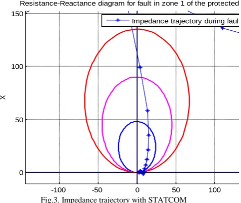
If fault occurs in zone one then results with and without STATCOM
Fig.2. Impedance trajectory without STATCOM
-100 -50 0 50 100
-20 0 20 40 60 80 100 120 140 160
R
X
Resistance-Reactance diagram for fault in zone 1 of the protected line
Copyright to IJIRSET www.ijirset.com 93
M.R. Thansekhar and N. Balaji (Eds.): ICIET’14
Fig.3. Impedance trajectory with STATCOM
If fault occurs in zone 2, the characteristic are as shown below
Fig.4. Impedance trajectory without STATCOM
Fig.4. Impedance trajectory with STATCOM
Fault occurs in zone two but characteristics shows in zone one this is adverse effect of STATCOM on distance relay.
The fault occurs in zone 3 the characteristics are as follows,
Fig.5. Impedance trajectory without STATCOM
Fig. 6. Impedance trajectory with STATCOM
Fault occurs in zone three but characteristics shows in zone one this is adverse effect of STATCOM on distance relay.
STATCOM at mid-point
STATCOM is connected at the midpoint and taking the results with and without STATCOM at different zones.
-100 -50 0 50 100
0 50 100 150
R
X
Resistance-Reactance diagram for fault in zone 1 of the protected line
Impedance trajectory during fault
-80 -60 -40 -20 0 20 40 60 80 100 0
20 40 60 80 100 120 140
R
X
Resistance-Reactance diagram for fault in zone 2 of the protected line Impedance trajectory during fault
-150 -100 -50 0 50 100
-40 -20 0 20 40 60 80 100 120 140
R
X
Resistance-Reactance diagram for fault in zone 2 of the protected line
Impedance trajectory during fault
-80 -60 -40 -20 0 20 40 60 80
-20 0 20 40 60 80 100 120 140
R
X
Resistance-Reactance diagram for fault in zone 3 of the protected line
Impedance trajectory during fault
-100 -50 0 50 100
-20 0 20 40 60 80 100 120 140
R
X
Resistance-Reactance diagram for fault in zone 3 of the protected line
Copyright to IJIRSET www.ijirset.com 94
M.R. Thansekhar and N. Balaji (Eds.): ICIET’14
C
B
A
G
G
RELAY
STATCOM
D
Z
1Z
2Z
3Fig.7.Single line diagram for distance relay with STATCOM
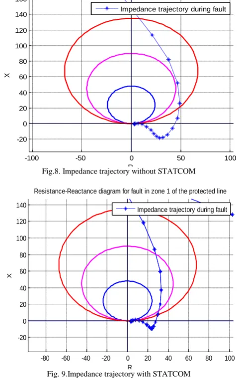
If fault occurs in zone one then results with and without STATCOM are
Fig.8. Impedance trajectory without STATCOM
Fig. 9.Impedance trajectory with STATCOM
It is seen that, the fault is in zone 1 but the characteristics shows it is just out of zone 1, STATCOM is not in fault zone that’s why there is no more effect.
If fault occurs in zone 2, the characteristic are as shown below
Fig.10. Impedance trajectory without STATCOM
Fig.11.Impedance trajectory with STATCOM
It is seen that the fault occurs in zone 2 but characteristics sows it is out of zone when STATCOM is connected in the line. STATCOM is in fault loop therefore it has great effect, distance relay get mal-operate.
-100 -50 0 50 100
-20 0 20 40 60 80 100 120 140 160
R
X
Resistance-Reactance diagram for fault in zone 1 of the protected line
Impedance trajectory during fault
-80 -60 -40 -20 0 20 40 60 80 100 -20
0 20 40 60 80 100 120 140
R
X
Resistance-Reactance diagram for fault in zone 1 of the protected line
Impedance trajectory during fault
-80 -60 -40 -20 0 20 40 60 80 100
0 20 40 60 80 100 120 140
R
X
Resistance-Reactance diagram for fault in zone 2 of the protected line
Impedance trajectory during fault
-50 0 50 100
0 50 100 150
R
X
Resistance-Reactance diagram for fault in zone 2 of the protected line
Copyright to IJIRSET www.ijirset.com 95
M.R. Thansekhar and N. Balaji (Eds.): ICIET’14
The fault occurs in zone 3 the characteristics are as follows,
Fig.12. Impedance trajectory without STATCOM
Fig.13.Impedance trajectory with STATCOM
It is seen that when STATCOM is connected in the line, the fault occurs in zone 3 but characteristics shows it is in zone 2
STATCOM at end point
STATCOM is connected at the midpoint and taking the results with and without STATCOM at different zones
C
B
A
G G
RELAY
STATCOM
D
Z
1Z
2Z
3Fig.14.Single line diagram for distance relay with STATCOM
If fault occurs in zone one then results with and without STATCOM are
Fig.14. Impedance trajectory without STATCOM
Fig.15. Impedance trajectory with STATCOM
It has not great impact because STATCOM is not in fault loop
If fault occurs in zone 2, the characteristic are as shown below
-80 -60 -40 -20 0 20 40 60 80
-20 0 20 40 60 80 100 120 140
R
X
Resistance-Reactance diagram for fault in zone 3 of the protected line
Impedance trajectory during fault
-80 -60 -40 -20 0 20 40 60 80
-20 0 20 40 60 80 100 120 140
R
X
Resistance-Reactance diagram for fault in zone 3 of the protected line
Impedance trajectory during fault
-100 -50 0 50 100
-20 0 20 40 60 80 100 120 140 160
R
X
Resistance-Reactance diagram for fault in zone 1 of the protected line
Impedance trajectory during fault
-80 -60 -40 -20 0 20 40 60 80 100
-20 0 20 40 60 80 100 120 140
R
X
Resistance-Reactance diagram for fault in zone 1 of the protected line
Copyright to IJIRSET www.ijirset.com 96
M.R. Thansekhar and N. Balaji (Eds.): ICIET’14
Fig.4. Impedance trajectory without STATCOM
Fig.7. Impedance trajectory with STATCOM
It has not great impact because STATCOM is not in fault loop
The fault occurs in zone 3 the characteristics are as follows,
Fig.6. Impedance trajectory without STATCOM
Fig.7. Impedance trajectory with STATCOM
Fault occurs in zone three but characteristics shows in zone two this is adverse effect of STATCOM on distance relay
V.C
ONCLUSIONThis paper present a detailed Simulation model of a transmission system of 400kv and 300km long having three zones and employing STATCOM for reactive power compensation. And plotted the mho characteristics. Fault is created in different zones and taking the zone wise results with and without statcom. When STATCOM is in fault loop then it has adverse effect on distance relay. Distance relay get mal-operate when STATCOM is in fault loop.
R
EFERENCES[1] H. Dehghani, B. Vahidi, B. Yousefi, F. Irannejad, N. Dehghani, “Distance relay’s fault detection in presence of resistive fault current limiter using superimposed and dc component methods.”Sci.Int. (Lahore), 25(3,425-432, 2013 ISSN 1013-5316; CODEN: SINTE 8
[2] A.P. Vaidya and Prasad A. Venikar,“Distance Protection Scheme for Protection of Long Transmission Line Considering the Effect of Fault Resistance by Using the ANN Approach”. International journal of Electrical and Electronics Engineering (IJEEE) ISSSN (PRINT):2231-5284vol-1,Iss-3,2012.62.
[3] Li-Cheng Wu,Chih-Wen Liu,Ching-Shan Chen, “modelling and testing of digital Distance Relay using MATLAB.”IEEE-2005
[4] SritejaAlapati and B.Durga Prasad , “Effect of Statcom on Distance Relay Performance in aTransmission Line “international journal of computer and Electrical engineering vol-4,no.4,aug 2012.
[5] X.Y. Zhou, H.F.Wang,R.K.Aggarwal, P.Beaumont, “The impact of STATCOM on Distance Relay” 15thPSCC,Liege22-26
August2005
[6] S.K.Sethy and J.K.Moharana, “Design, Analysis and Simulation of Linear Model of a STATCOM for Reactive Power Compensation with Variation of DC-link Voltage.” International
-80 -60 -40 -20 0 20 40 60 80 100 0
20 40 60 80 100 120 140
R
X
Resistance-Reactance diagram for fault in zone 2 of the protected line
Impedance trajectory during fault
-80 -60 -40 -20 0 20 40 60 80 -20
0 20 40 60 80 100 120
R
X
Resistance-Reactance diagram for fault in zone 2 of the protected line Impedance trajectory during fault
-80 -60 -40 -20 0 20 40 60 80
-20 0 20 40 60 80 100 120 140
R
X
Resistance-Reactance diagram for fault in zone 3 of the protected line
Impedance trajectory during fault
-60 -40 -20 0 20 40 60 80
-20 0 20 40 60 80 100 120 140
R
X
Resistance-Reactance diagram for fault in zone 3 of the protected line
Copyright to IJIRSET www.ijirset.com 97
M.R. Thansekhar and N. Balaji (Eds.): ICIET’14
Journal of Engineering and Innovative Technology (IJEIT) Vol. 2, Issue 5, November 2012.
[7] JavidAkhtar and Sinto George, “Modeling and Simulation of STATCOM for a power system network using MATLAB/SIMULINK.” IOSR Journal of Engineering (IOSRJEN) ISSN: 2250-3021 Volume 2, Issue 8 (August 2012), PP 12-17
[8] N. G. Hingorani and L. Gyugyi, Understanding FACTS: Concepts & Technology of Flexible AC Transmission Systems.” New York: Wiley, 1999.
[9] ParmarHiran S, Vamsi Krishna K, Ranjit Roy, “shunt Compensation for power quality Improvement using a STATCOM controller” ACEEE International journal on electrical and power engineering vol1, no.2, july2010.
[10] A - T. M. Yesansure and T. G. Arora, “Numerical Quadrilateral Distance relay.” International Journal of Innovative Research in Science, Engineering and Technology Vol. 2, Issue 7, July 2013 [11] Yashasvi B, Vidushi K and Ramesh P, “SIMULATION OF MHO
CHARACTERISTICS FOR TRANSMISSION LINE PROTECTION USING PSCAD. International Journal of Research in Engineering & Applied Sciences IJREAS Volume 2, Issue 2 (February 2012) ISSN: 2249-3905
[12] G. Benmouyal, "Removal of Decaying DC in Current Waveforms Using Digital Mimic Filtering," IEEE Trans. on Power Delivery, vol. 10, no. 2, April 1995, pp. 621-63. [13] H. Bentarzi,A.Ouadi and A.Zitouni, “Distance Protective System