ISSN(Online): 2320-9801 ISSN (Print): 2320-9798
I
nternational
J
ournal of
I
nnovative
R
esearch in
C
omputer
and
C
ommunication
E
ngineering
(A High Impact Factor, Monthly, Peer Reviewed Journal)
Vol. 4, Issue 1, January 2016
AMBA 3 AHB LITE PROTOCOL Verification
through an Efficient and Reusable Environment
with an Optimum Assertion and Functional and
Code Coverage in UVM
Pragati Agarwal
M. Tech Student (VLSI), Department of Electrical, Electronics & Communication Engineering, NCU University
(Formerly ITM University), Gurgaon, (Haryana), India
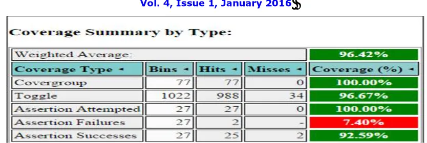
ABSTRACT: Verification is the most integral part of chip manufacturing and testing and is as important as the designing. Verification provides with the actual implementation and functionality of a Design under Test (DUT) and checks if it meets the specifications or not. In this paper, an AMBA 3 AHB LITE protocol has been verified as per the design specifications. The environment so created completely wraps the design under verification and observes an optimum functional, code and assertion based coverage. The coverage so obtained is 92.59% assertion based coverage, 100% functional coverage and 94.9% Code Coverage using UVM. The total coverage so obtained is 96.42%.
KEYWORDS: Assertions; Coverage; Environment; Driver; Randomization; UVM; Sequencer; Monitor; Agent I. INTRODUCTION
Verification being a very important part of the industry is a very tedious job and hence requires a lot of efforts to reach a successful outcome. With time, verification methodologies have evolved from the oldest one being the advisor in the 2000 to the latest UVM in the 2013. UVM methodology is a standard methodology mentioned in Accellera and created by the efforts of Synopsys, Cadence and Mentor Graphics in the year 2013. One of the key features of UVM includes code reusability in where common parts of code are abstracted out in modules and are included in the library. These modules can then be easily used by some standard syntax and by merely including the name of the library. UVM hence, helps in reducing the efforts of a verification engineer and hence reduces the overall time to verify a chip. With increasing complexity of the input constraints and the need for better control of the statistical distribution, imperative test benches are being replaced by more declarative specification methods using languages such as UVM [1].
A. Need of Verification
Exponentially increasing complexity of chips particularly SOCs made verification more challenging. Major portion of development time (~70%) of a complex SOC is spent on verification. Reducing verification effort or time spent on verification has a strong impact on Time-to-Market (TTM). In order to satisfy such growing complex verification needs powerful verification languages and verification methodologies are employed [2].
In general IP Verification requires in depth verification with coverage based and constraint random simulation technique, which needs an advanced test bench equipped with various components such as coverage monitors and sequencers. But if an IP was fully verified before and has a minor design change, it is not necessary to verify all features in detail. A few directed cases and simple checkers might be sufficient [3].
ISSN(Online): 2320-9801 ISSN (Print): 2320-9798
I
nternational
J
ournal of
I
nnovative
R
esearch in
C
omputer
and
C
ommunication
E
ngineering
(A High Impact Factor, Monthly, Peer Reviewed Journal)
Vol. 4, Issue 1, January 2016
B. UVM features
UVM provides a method of testbench i.e. how to use the SystemVerilog tools to create effective, reusable and scalable testbenches. UVM provides base class libraries and macros that are open source and are supported by many vendors. UVM provides many features to develop a reusable test environment. The component hierarchy provides a basic skeleton for the testbench. UVM testbench has a number of class objects that are connected hierarchically. The top is a component that is created by UVM. Top module consists of test and DUT. The test object instantiates the environment and configures the environment for a particular test. There may be multiple tests, each of which configures the environment for that particular test. The environment has one or more agents. Agents have the verification components that generate stimulus to the DUT and monitor the DUT behavior. One agent may have sequencer, driver and the other agent may have monitor, checker and scoreboard etc. So the basic structure of all verification environments is fixed and it increases reusability of the environment. In UVM there are many options of reporting a message. The user can specify actions based on message verbosity and severity. UVM provides a configuration database that is a common area for storing the values and user can retrieve it from the same area when needed. Transaction Level Modelling (TLM) makes transfer of information from a producer to consumer by a task or function. There are three ways of data transfer between components. Producer (initiator in this scenario) pushes data to consumer (Target in this scenario) using TLM PUT port. Consumer (initiator in this scenario) pulls data directly from producer (Target in this scenario) using TLM GET port. Producer and consumer both are initiator and uses a FIFO as a target. In UVM factory methods are used to change the type of object at the run time. In addition to infrastructure features UVM provides communication channels for analysis that observe the activities in DUT and record it, make determinations and provide feedback for coverage analysis. Analysis components are like monitor, coverage collector, scoreboard etc. The most important is that, generation of tests is independent of the environment that makes the behavior separate from structure. User wants to be able to change the entire transaction dynamically i.e. at the run time without changing the environment.
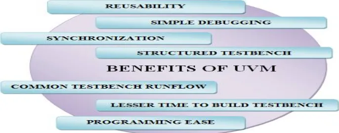
E. Benefits of UVM
UVM uses Transaction Level interfaces for connecting verification components in the environment and provides added features using which objects in the environment can be modified during the run time. Building the test bench environment using UVM have many advantages like reusability, lesser time to build testbenches, better synchronization among verification components, better simulation statistics, simple debugging of code and the most important same test bench architecture and run phases. Benefits of UVM are visualized in Figure 1. An environment prepared using UVM give better performance in terms of memory usage and CPU time. UVM provides much more robust debugging facilities as messages reporting can be done with its severity level, category and verbosity level [7]. So message reporting can be done in a managed way. Moreover the verification components and methods are modular and can be reused across different designs and even across different design teams. UVM also provides TLM ports those can be parameterized to the type of transaction to synchronize the communication among components [7]. The most important of UVM is that it has a well defined testbench structure and topology that can’t be changed. This standardization of testbench structure makes the environment more reusable from project to project. The execution flow of testbench is determined by built in phases and sub phases those make execution order fixed during simulation.
ISSN(Online): 2320-9801 ISSN (Print): 2320-9798
I
nternational
J
ournal of
I
nnovative
R
esearch in
C
omputer
and
C
ommunication
E
ngineering
(A High Impact Factor, Monthly, Peer Reviewed Journal)
Vol. 4, Issue 1, January 2016
One of the major advantages of UVM is that the modules are reusable and the work flow is common. If every verification engineer had his own way of verifying a component, then it would become very difficult for anyone to understand each and every method. The reason being, everyone would have created a block level testbench with their own unique style. Hence, there was a need to come up with a common platform which would be easier to understand, and could be used by anyone without investing a huge amount of time. The other major advantage of using a common methodology is to increase productivity. This is because, if we have a common platform then using a common set of templates is ensured which in turn helps in maintaining consistency. Also, major simulators support UVM and it is an Accellera standard [8].
II. RELATED WORK
UVM was announced by The Accellera Systems Initiative on December 23rd, 2009 and its first version was approved on February 18th, 2011. UVM as compared to simple SystemVerilog offers a single standard, industry-wide solution to the challenges of design verification. The reason being , it has a large number of libraries that are reused at a large number of places inside the code while creating a VIP. The history of methodologies and innovations on which the UVM is built is given by the timeline given below in Fig. 2.
aAdvisor1 eRM1 URM1 OVM1,3 UVM1,2,3 UVM-1.1a,b,c,d1,2,,3
20002002 2007 2008 20102011-2013
Contributions From:
2003 2006 1Cadence
RVM2 AVM3 2Synopsys
VMM2 3Mentor
Fig. 2. Verification Methodology Timeline [10]
III.DUT-AMBA3AHBLITEPROTOCOL
A. Design Considerations:
High clock frequency. Burst Transfers.
High Bandwidth Operation. Non Tri-state Implementation.
Wide Data Bus Configuration 64, 128, 256, 512, and 1024 bits. Single Clock Edge Operation.
High Performance.
B. Description of DUT:
It has a single master AHB-LITE system design with one AHB-LITE master and three AHB-LITE slaves. The bus interconnect logic consists of one address decoder and a slave-to-master multiplexor. The decoder monitors the address from the master so that the appropriate slave is selected and the multiplexor routes the corresponding slave output data back to the master.
The main component types of an AHB-LITE system are described in: • Master
• Slave
• Decoder
ISSN(Online): 2320-9801 ISSN (Print): 2320-9798
I
nternational
J
ournal of
I
nnovative
R
esearch in
C
omputer
and
C
ommunication
E
ngineering
(A High Impact Factor, Monthly, Peer Reviewed Journal)
Vol. 4, Issue 1, January 2016
Fig. 3. ARCHITECTURE OF AMBA 3 AHB LITE PROTOCOL
IV.UVM TESTBENCH ARCHITECTURE
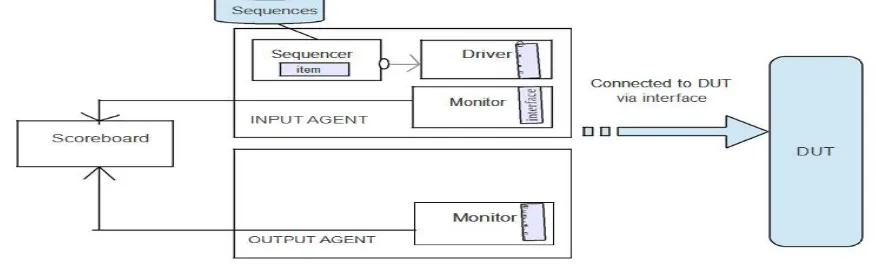
In order to understand the verification environments, we must first understand the architecture in a broader view. The architecture is composed of various components that are integrated in a proper manner to form the required VIP. These components include a sequencer, sequence item, driver, monitor, collector, agent, scoreboard and a DUT (Design Under Test). These components can be connected to each other as seen below in Fig. 4.
Fig. 4. UVM Testbench Architecture[8]
UVM Components
A few of the components used in the UVM are given as under:
A. Driver
It is one of the components that is used while creating a VIP. The driver requests for signals or data transactions from the sequencer. These transactions are then processed in the run phase and then sent to the DUT via an interface for verifying it. Any basic driver that we create is extended from the base class named as uvm_driver which is a parameterized class with REQ (Request) and RES (Response) as its two parameters. These parameters are of type sequence_item which is in fact a transaction. Here, we may also include pipelining where a number of parallel stages are considered. At first, we declare a virtual interface which is used for communicating with the design under verification, and then other phases are included such as the run_phase et. al.
B. Sequencers and Sequences
ISSN(Online): 2320-9801 ISSN (Print): 2320-9798
I
nternational
J
ournal of
I
nnovative
R
esearch in
C
omputer
and
C
ommunication
E
ngineering
(A High Impact Factor, Monthly, Peer Reviewed Journal)
Vol. 4, Issue 1, January 2016
driver is shown in Fig. 5. as below:
Fig. 5. Connection of Sequencer and Driver [8]
These sequence items are created by putting a lot of constraints that are required in order to generate the needed transactions for verifying the DUT.
C. Monitor
It is not an active component and performs two functions; one is performing verification and the other is to collect transactions from the interface and thereby performing checking and hence coverage. Here, sampling of transactions are done and then these transactions are then written to the analysis port. The coding part is almost similar to the driver.
D. Agents
These components could either be active or passive, and are used as a container that is used for instantiating the driver, sequencer and monitor. When the agent is in active mode, the above three components namely driver, sequencer and the monitor are created, while in the passive mode it only creates the monitor. The complete environment is built by integrating these components in a proper required fashion.
V. COMPILATIONINUVM
In order to understand the architecture, we must first learn about the various phases of UVM. These are:
– the build_phase: this is the top level phase which is used to build all the components required inside the UVM environments
– the connect_phase: it is followed by the build_phase where the created components are connected to each other. Analysis port and export may be used here.
– the end_of_elaboration_phase: post elaboration activities are placed here. For example, we can print topology information.
– the start_of_simulation_phase: here, the created components are initialized. – the run_phase: this phase is like a task which consumes some time.
– the extract, check and report_phase: these are the phases that is executed at the end [8].
VI.DESIGNSIMULATION A. Randomization
Random testing is more effective than a traditional approach of directed testing. One can easily create tests that can find hard-to-reach corner cases, by specifying constraints. UVM allows users to specify constraints in a more compact and declarative way. The constraints are then processed by a solver that generates random values that meet the constraints [5].
B. Output Waveform :
ISSN(Online): 2320-9801 ISSN (Print): 2320-9798
I
nternational
J
ournal of
I
nnovative
R
esearch in
C
omputer
and
C
ommunication
E
ngineering
(A High Impact Factor, Monthly, Peer Reviewed Journal)
Vol. 4, Issue 1, January 2016
Fig. 6. Output Waveform of AMBA 3 AHB LITE Protocol
C. Coverage
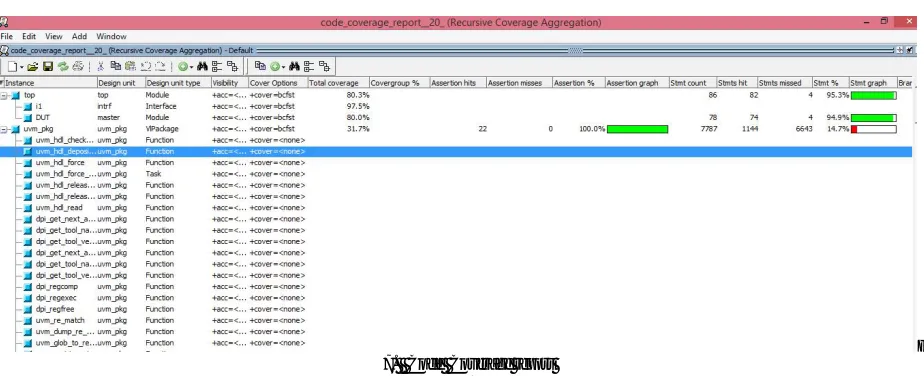
1) Code Coverage Report
Fig. 7. Code Coverage report
2) Assertion Coverage
Assertions are mechanism or tool used by HDL’s (VHDL and Verilog) to detect a design’s expected behavior. The assertion fails if a property that is being checked for in a simulation does not behave the way we expect it to or we can say that, the assertion fails if a property that is forbidden from happening in a design happens during simulation. It helps capturing the designer’s interpretation of the specification [5]. The assertion coverage based on randomization function assertion is shown in figure 8.
3) Total Coverage Percentage
ISSN(Online): 2320-9801 ISSN (Print): 2320-9798
I
nternational
J
ournal of
I
nnovative
R
esearch in
C
omputer
and
C
ommunication
E
ngineering
(A High Impact Factor, Monthly, Peer Reviewed Journal)
Vol. 4, Issue 1, January 2016
Fig. 8. Coverage report including functional and assertion based coverage
VII. CONCLUSION AND FUTURE WORK
The code for environment has been simulated. The outputs from DUT have been observed. Environment contains the
instances or the objects of the driver, monitor, sequencer, agent, comparator, package and the DUT. The task performed by the monitor, driver and sequencer, agent is called along with the mailboxes which contain the received and sent information in the form of randomized packets. The mailbox implemented to carry the packets shows results after every transaction. The environment so created completely wraps the design under verification and observes an optimum functional, code and assertion based coverage. Bins have been created based on the constraints and 100% functional coverage has been obtained on them. The coverage so obtained is 92.59% assertion based coverage , 94.9% code coverage and 100% functional coverage using UVM. The total coverage so obtained is 96.42%.REFERENCES
1. Sutherland S, Davidmann S, Flake P, “SystemVerilog for Design: A Guide to Using SystemVerilog for Hardware Design and Modeling,” Norwell, MA: Kluwer Academic Publishers, 2003
2. SudhishNaveen, BR Raghavendra, YagainHarish, "An Efficient Method for Using Transaction Level Assertions in a Class Based Verification Environment," International Symposium on Electronic System Design,pp.72 -76, 2011
3. Yun Young-Nam, Kim Jae-Beom, Kim Nam-Do, Min Byeong, “Beyond UVM for practical SoC verification,” SoC Design Conference (ISOCC), pp. 158 – 162, Nov 2011.
4. Welp Tobias, Kitchen Nathan, and Kuehlmann Andreas, “Hardware Acceleration for Constraint Solving for Random Simulation,”IEEE Transactions On Computer-Aided Design of Integrated Circuits And Systems, vol-31, No. 5, May 2012
5. http://www.systemverilog.in/systemverilog_introduction.php
6. Ahlawat Deepika, Shukla Neeraj Kr., "DUT Verification Through an Efficient and Reusable Environment with Optimum Assertion and Functional Coverage in System Verilog", International Journal of Advanced Computer Science and Applications, Vol. 5, No. 4, 2014
7. Nangia Rakhi, Shukla Neeraj K., “Functional Verification of I2C Core using SystemVerilog,” International Journal of Engineering, Science and Technology (IJEST), 2014,Vol.6, No.4, pp.31-44.
8. Vanessa R. Cooper, “Getting Started with UVM,” First Edition, Austin, USA, © 2013, 2012 Verilab, Inc. - http://www.verilab.com
9. Nangia Rakhi, Shukla Neeraj Kr., Srinath Nate, "Roles and Responsibilities of Verification Languages, Verification Methodologies and Verification Toolsfor Design Verification of a DUT", JOURNAL OF VLSI DESIGN TOOLS & TECHNOLOGY, VOL 5, NO 3(2015)
10. Kathleen A Meade and Sharon Rosenberg, “A Practical Guide to Adopting the Universal Verification Methodology (UVM),” Second Edition
11. http://www.eecs.umich.edu/courses/eecs373/readings/ARM_IHI0033A_AMBA_AHB-Lite_SPEC.pdf
12. N.Karthik, M.Gurunadha Babu and Ms. Muni Praveena Rela, "Assertion Based Verification of AMBA AHB Using System Verilog"International Journal and Magazine of Engineering, Technology, Management and Research, ISSN No: 2348-4845, Volume No: 2 (2015), Issue No: 7 (July)
BIOGRAPHY
![Fig. 2. Verification Methodology Timeline [10]](https://thumb-us.123doks.com/thumbv2/123dok_us/1465226.1179544/3.595.66.549.395.505/fig-verification-methodology-timeline.webp)